EP0806690B1 - Drehvorrichtung und Lichtstrahl-Ablenkungsgerät - Google Patents
Drehvorrichtung und Lichtstrahl-Ablenkungsgerät Download PDFInfo
- Publication number
- EP0806690B1 EP0806690B1 EP97107123A EP97107123A EP0806690B1 EP 0806690 B1 EP0806690 B1 EP 0806690B1 EP 97107123 A EP97107123 A EP 97107123A EP 97107123 A EP97107123 A EP 97107123A EP 0806690 B1 EP0806690 B1 EP 0806690B1
- Authority
- EP
- European Patent Office
- Prior art keywords
- rotor
- thrust bearing
- radial bearing
- area
- rotating device
- Prior art date
- Legal status (The legal status is an assumption and is not a legal conclusion. Google has not performed a legal analysis and makes no representation as to the accuracy of the status listed.)
- Expired - Lifetime
Links
- 230000000052 comparative effect Effects 0.000 description 6
- 238000004519 manufacturing process Methods 0.000 description 6
- 230000003287 optical effect Effects 0.000 description 4
- 238000010276 construction Methods 0.000 description 2
- 230000000694 effects Effects 0.000 description 2
- 238000000034 method Methods 0.000 description 2
- 108091008695 photoreceptors Proteins 0.000 description 2
- DBGSRZSKGVSXRK-UHFFFAOYSA-N 1-[2-[5-[2-(2,3-dihydro-1H-inden-2-ylamino)pyrimidin-5-yl]-1,3,4-oxadiazol-2-yl]acetyl]-3,6-dihydro-2H-pyridine-4-carboxylic acid Chemical compound C1C(CC2=CC=CC=C12)NC1=NC=C(C=N1)C1=NN=C(O1)CC(=O)N1CCC(=CC1)C(=O)O DBGSRZSKGVSXRK-UHFFFAOYSA-N 0.000 description 1
- LLQHSBBZNDXTIV-UHFFFAOYSA-N 6-[5-[[4-[2-(2,3-dihydro-1H-inden-2-ylamino)pyrimidin-5-yl]piperazin-1-yl]methyl]-4,5-dihydro-1,2-oxazol-3-yl]-3H-1,3-benzoxazol-2-one Chemical compound C1C(CC2=CC=CC=C12)NC1=NC=C(C=N1)N1CCN(CC1)CC1CC(=NO1)C1=CC2=C(NC(O2)=O)C=C1 LLQHSBBZNDXTIV-UHFFFAOYSA-N 0.000 description 1
- 239000000853 adhesive Substances 0.000 description 1
- 230000001070 adhesive effect Effects 0.000 description 1
- 229910010293 ceramic material Inorganic materials 0.000 description 1
- 238000001514 detection method Methods 0.000 description 1
- 239000011810 insulating material Substances 0.000 description 1
- 239000000463 material Substances 0.000 description 1
- 239000004065 semiconductor Substances 0.000 description 1
- 238000004381 surface treatment Methods 0.000 description 1
Images
Classifications
-
- G—PHYSICS
- G02—OPTICS
- G02B—OPTICAL ELEMENTS, SYSTEMS OR APPARATUS
- G02B26/00—Optical devices or arrangements for the control of light using movable or deformable optical elements
- G02B26/08—Optical devices or arrangements for the control of light using movable or deformable optical elements for controlling the direction of light
- G02B26/10—Scanning systems
- G02B26/12—Scanning systems using multifaceted mirrors
- G02B26/121—Mechanical drive devices for polygonal mirrors
Definitions
- the present invention relates to a rotating device provided with a dynamic pressure bearing in which a space is formed between a rotor and a lower thrust bearing and between the rotor and a radial bearing by the action of a dynamic pressure generating groove with rotation of the rotor. Further, the present invention relates to a light beam deflecting apparatus using the rotating device.
- the rotating device using the dynamic pressure bearing is composed of upper and lower thrust bearings, a radial bearing, and a rotor rotatable on the radial bearing.
- the rotating device using the dynamic pressure bearing is composed of upper and lower thrust bearings, a radial bearing, and a rotor rotatable on the radial bearing.
- ambient temperature surrounding the rotor is raised by heat generated from a motor coil during rotation of the rotor.
- the ambient temperature rise becomes approximate 40 °C and the temperature of the rotor is also raised.
- the rotating device using the dynamic pressure bearing requires the high grade balance as discussed above, if the temperature is raised, the rotor becomes unbalanced, resulting in galling and burning so that a required performance of the rotating device may not be achieved.
- the ambient temperature rise becomes 40 degrees, the balance grade may happen to lower from G1 grade to G2 grade, increasing vibration to an extent of ten times heavier.
- the light beam deflecting device the deflected light beam is so deviated that high quality image can not be formed.
- thermal expansion in the structural material of the rotor As factors which cause the unbalance of the rotor due to temperature change, thermal expansion in the structural material of the rotor, thermal expansion in plural structural members when the rotor is composed of the plural structural members, influence of adhesive to joint the plural structural members may be listed, and they are considered to cause various thermal expansions differing in extent or location in the rotor.
- the objective of the present invention is to provide a rotating device or a light deflecting apparatus comprising a dynamic bearing with a structure which causes less balance fluctuation and is resistant to balance fluctuation even when the balance degree of the rotor becomes poor due to various causes,
- the rotating device In a rotating device provided with a dynamic pressure bearing in which a space is formed between a rotor and a lower thrust bearing and between the rotor and a radial bearing by an action of dynamic pressure generating grooves with rotation of the rotor, the rotating device satisfies the following formula: [(a radial bearing area) / (thrust bearing area)] x (rotor weight) ⁇ 300g wherein the radial bearing area (mm 2 ) is an area of the rotor facing the radial bearing, the thrust bearing area (mm 2 ) is an area of the rotor facing the lower thrust bearing, and the rotor weight (g) is the weight of the rotor.
- a magnet on a lower section of the rotor is provided a magnet, and on a position facing the magnet is provided a coil so that the rotor is rotated together with the magnet by switching on an electric circuit for the coil.
- a polygonal mirror On the rotor is provided a polygonal mirror.
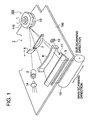
- Fig. 1 is a perspective view showing an embodiment of a unit of an optical light beam scanning system in which a rotating device provided with a dynamic pressure bearing is used as a light beam deflecting device.
- reference numeral 100 is a base on which a rotating device is mounted
- 2 is a collimator (a optical system for correcting a shape of a beam)
- 5 is a cylindrical lens
- 116 is a polygonal mirror
- 7 is a f ⁇ lens
- 8 is a second cylindrical lens
- 9 is a reflecting mirror
- 10 is a photoreceptor drum.
- 11 is a timing detecting mirror
- 12 is a synchronization detecting means
- 13 is a driving motor for the polygonal mirror 116.
- a beam emitted from a semiconductor type laser emitting device 1A is shaped in parallel light beam by the collimator 2. The beam is brought through the first cylindrical lens to incidence on the rotating polygonal mirror and then is reflected from it.
- the reflected beam passes through the second image forming optical system composed of the f ⁇ lens 7 and the second cylindrical lens 8 and is reflected by the reflecting mirror 9 so as to scan in the form of a spot of a predetermined diameter in the main scanning direction on the photoreceptor drum 10.
- the synchronization detection for each scanning line is conducted by bringing the beam through the mirror 11 to incident on the synchronization detector 12 before starting the main scanning.
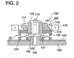
- Fig. 2 is an enlarged view of the rotating device shown in Fig. 1 and is a sectional view showing the entire construction of a rotating device 101 provided with a dynamic pressure device.
- the rotating device 101 comprises a lower thrust bearing 103, a radial bearing 105, a retaining sheet plate 118 used as the preventing means for preventing the rotor from slipping out, a screw 119 and the rotor 104.
- the lower thrust bearing is provided with a dynamic pressure bearing.
- the base 100 On the base 100 is fixed vertically a core shaft 102 for supporting the rotating device 101.
- a disk-shaped lower thrust bearing 103 made of a ceramic material and a cylindrical radial bearing 105 are fitted around the core shaft 102 and are mounted in such order on the base 100.
- the retaining sheet plate 118 used as the slipping-out preventing means and the screw 119 With the retaining sheet plate 118 used as the slipping-out preventing means and the screw 119, the lower thrust bearing 103 and the radial bearing 105 are fixed on the base 100.
- the lower thrust bearing 103 and the radial bearing 105 may be made in one body.
- the rotor 104 is fitted around the radial bearing 105 and is located between the retaining sheet plate 118 and the lower thrust bearing 103 in such a manner that the rotor 104 is rotatable around the radial bearing 105.
- Each of the radial bearing 105 and a rotor core 107 are subjected to a high precision surface treatment so that a gap of 1 to 7 ⁇ m is formed between the radial bearing 105 and the rotor core 107.
- a support section 114 is fixed on the outer periphery of the rotor core 107 and the polygonal mirror 116 on which plural reflecting mirror surfaces 115 are formed is fixed on the support section 114 with a fixing member 117, thereby forming the rotor unit 104 rotatable in one body around the radial bearing 105.
- the rotor 104 means all members actually rotating as one body.
- the rotor 104 comprises the rotor core 107, the support section 114, the polygonal mirror 116 on which plural reflecting mirror surfaces 115 are formed, the fixing member 117 and magnet 125 which is mentioned later on.
- the retaining sheet plate 118 and the screw 119 are used without using the upper thrust bearing.
- the reason is to provide a function to fix the lower thrust bearing 103 and the radial bearing 105 in addition to the function to prevent the slipping-out. Since the retaining sheet plate 118 and the screw 119 do not need manufacturing precision and achieve the above two functions, the number of machinery parts can be reduced and the device can be made at lower cost. Needless to say, it may be possible to provide the upper thrust bearing between the retaining sheet plate 118 and the radial bearing 105.
- the dynamic pressure generating groove is provided not only on the lower thrust bearing, but also can be provided on the upper thrust bearing. However, as demonstrated in the this embodiment, in the case that the dynamic pressure generating groove 121 is formed only on the lower thrust bearing 103, the rotation precision is not affected. Since the dynamic pressure generating groove 121 is not required to be formed on the upper thrust bearing, the number of processes to form the dynamic pressure generating groove can be reduced and the device can be manufactured at lower cost.
- an axial type driving motor 13 As a driving source to rotate the rotor 104, an axial type driving motor 13 is used.
- a stator coil 124 is provided together with an insulating material 123 on the base 100 and magnets 125 are provided at a position facing the stator coil 124 on a lower section of the supporting section 114 of the rotor 104.
- the stator coil 124 When the stator coil 124 is activated, the rotation of the rotor 104 is induced.
- the rotating device 101 of the present invention is constructed as explained above and make it possible to attain extremely high speed operation.
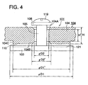
- test devices were prepared by varying the diameter D1 (mm) of the thrust bearing, the inside diameter D2 (mm) of the rotor, the height H (mm) of the rotor, the weight W (g) of the rotor as shown in Table 1 and anti-unbalance capability test (balance retaining capability test) was conducted on the test devices.
- Index [(a radial bearing area) / (thrust bearing area)] x (rotor weight) wherein the radial bearing area (mm 2 ) is the area of the rotor 104 facing the radial bearing 105, the thrust bearing area (mm 2 ) is the area of the rotor 104 facing the lower thrust bearing 103, and the rotor weight (g) is the weight of the rotor 104.
- the index defined by the present invention since the initial rotation speed at which the balance adjustment is initially conducted becomes high, the number of the balance adjustment conducted while increasing a rotation speed stepwise to the normal rotation speed can be reduced. As a result, as accompanying effects, manufacturing cost can be greatly reduced and a manufacturing time period can also be greatly shortened.
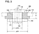
- chamfering is applied on corners 104A, 104B of the surfaces of the rotor 104 facing the radial bearing 105, and cut-out portion 104 is provided on the outside of the surface of the rotor 104 facing the lower thrust bearing 103.
- the radial bearing surface (mm 2 ) is the area of the surface of the rotor 104 facing the radial bearing 105
- the width applied with the chamfering is not larger than 0.5 mm, the chamfering is deemed as not being applied, H' is deemed as being equal to H.
- the surface of the rotor 104 facing the radial bearing 105 is slanted in positional relation to the surface of the radial bearing 105, when the width of the slant in the radial direction is not larger than several millimeters, the slant is negligible and the average inner diameter of the slanted rotor is used as D2.
- the thrust bearing surface (mm 2 ) is the area of the surface of the rotor 104 facing the thrust bearing 105
- the width applied with the chamfering on the rotor 104 is not larger than 1 mm, the chamfering is deemed as not being applied, D2' is deemed as being equal to D2. If a width of the cut-out portion in the radial direction is not larger than several millimeters, the width of the cut-out portion is negligible and D1' is deemed as being equal to D1.
- the rotor weight (g) is the weight of the rotor, that is, a total weight of actually rotating members.
- the total weight includes a weight of the magnet and the polygonal mirror.
- Index calculated by [(a radial bearing area)/ (thrust bearing area)] x (rotor weight) not larger than 300, the abovementioned effects can be obtained. It may be preferable that Index is not larger than 100. It may be more preferable that Index is not larger than 50.
- the present invention in rotating devices provided with a dynamic pressure bearing in which a space is formed between a rotor and a lower thrust bearing and between the rotor and a radial bearing by action of dynamic pressure generating grooves with rotation of the rotor, by satisfying the following formula among the radial bearing area (mm 2 ) which is the area of the rotor 104 facing the radial bearing 105, the thrust bearing area (mm 2 ) which is the area of the rotor 104 facing the lower thrust bearing 103, and the rotor weight (g) which is the weight of the rotor 104, regardless of the shape of the rotor, [(a radial bearing area) / (thrust bearing area)] x (rotor weight) ⁇ 3000g even if unbalance takes place on the rotor 104 due to various factors, the present invention can provide a dynamic pressure bearing having a structure which causes less balance fluctuation and is resistant to balance fluctuation.
- the rotating device since the above rotating device comprises the slipping-out preventing means which do not need a relatively high processing accuracy, the rotating device can be manufactured at low cost.
- the dynamic pressure generating groove is provided only on the lower thrust bearing, the number of processes to make the pressure generating groove which needs relatively high processing accuracy can be reduced. As a result, the rotating device can be manufactured at lower cost.
- magnets are provided on the lower section of the rotor and a coil is provided on a position facing the magnet, by switching on an electric circuit for the coil, the rotor can be easily rotated at a high speed.
Landscapes
- Physics & Mathematics (AREA)
- General Physics & Mathematics (AREA)
- Optics & Photonics (AREA)
- Sliding-Contact Bearings (AREA)
- Connection Of Motors, Electrical Generators, Mechanical Devices, And The Like (AREA)
- Mechanical Optical Scanning Systems (AREA)
- Facsimile Scanning Arrangements (AREA)
Claims (7)
- Drehvorrichtung (101) mit:dadurch gekennzeichnet, dass eine Radiallagerfläche (mm2), welche von einer dem Radiallager zugewandten Fläche des Rotors gebildet ist, eine Axiallagerfläche (mm2), welche von einer dem unteren Axiallager zugewandten Fläche des Rotors gebildet ist, und das Rotorgewicht (g) so festgelegt sind, dass sie die folgende Formel erfüllen:einem Rotor (104);einem Radiallager (105) zur Einstellung einer Drehachse des Rotors;einem unteren Axiallager (103), auf welchem ein Teil des Rotors (104) läuft, so dass ein Teil des Gewichts des Rotors auf dem unteren Axiallager ruht;einer dynamischen Druckerzeugungsvorrichtung (121) zur Erzeugung eines dynamischen Drucks mit der Drehung des Rotors, so dass ein erster Spalt zwischen dem Radiallager (105) und dem Rotor (104) und ein zweiter Spalt zwischen dem unteren Axiallager (103) und dem Rotor (104) gebildet wird,
- Vorrichtung gemäß Anspruch 1, wobei die Formel [(Radiallagerfläche) / (Axiallagerfläche)] x (Rotorgewicht) < 100g lautet.
- Vorrichtung gemäß Anspruch 2, wobei die Formel [(Radiallagerfläche) / (Axiallagerfläche)] x (Rotorgewicht) < 30g lautet.
- Vorrichtung gemäß Anspruch 1 mit ferner einer Herausgleitschutzvorrichtung (118), die auf einem oberen Bereich des Radiallagers vorgesehen ist, um zu verhindern, dass der Rotor aus dem Radiallager heraus gleitet.
- Vorrichtung gemäß Anspruch 1, wobei die dynamische Druckerzeugungsvorrichtung (121) eine dynamische Druckerzeugungsrille umfasst, die an dem unteren Axiallager (103) angeordnet ist.
- Vorrichtung gemäß Anspruch 1 mit ferner einem Magneten (125), der auf einem unteren Abschnitt des Rotors angeordnet ist, und einer Spule (124), die dem Magneten zugewandt angeordnet ist, wobei der Rotor durch Anschalten einer elektrischen Schaltung für die Spule gedreht wird.
- Vorrichtung gemäß Anspruch 1, wobei der Rotor derart gebaut ist, dass ein polygonaler Spiegel (115) an dem Rotor angebracht ist und die Drehvorrichtung zum Ablenken eines Laserstrahls eingesetzt wird.
Applications Claiming Priority (3)
| Application Number | Priority Date | Filing Date | Title |
|---|---|---|---|
| JP8114756A JPH09303383A (ja) | 1996-05-09 | 1996-05-09 | 回転装置及び光偏向装置 |
| JP114756/96 | 1996-05-09 | ||
| JP11475696 | 1996-05-09 |
Publications (3)
| Publication Number | Publication Date |
|---|---|
| EP0806690A2 EP0806690A2 (de) | 1997-11-12 |
| EP0806690A3 EP0806690A3 (de) | 1998-12-30 |
| EP0806690B1 true EP0806690B1 (de) | 2003-08-06 |
Family
ID=14645904
Family Applications (1)
| Application Number | Title | Priority Date | Filing Date |
|---|---|---|---|
| EP97107123A Expired - Lifetime EP0806690B1 (de) | 1996-05-09 | 1997-04-30 | Drehvorrichtung und Lichtstrahl-Ablenkungsgerät |
Country Status (4)
| Country | Link |
|---|---|
| US (1) | US5946122A (de) |
| EP (1) | EP0806690B1 (de) |
| JP (1) | JPH09303383A (de) |
| DE (1) | DE69723907D1 (de) |
Families Citing this family (6)
| Publication number | Priority date | Publication date | Assignee | Title |
|---|---|---|---|---|
| JP3622168B2 (ja) * | 1997-07-22 | 2005-02-23 | コニカミノルタホールディングス株式会社 | 画像形成装置 |
| DE29811486U1 (de) * | 1998-06-26 | 1998-10-08 | Sick AG, 79183 Waldkirch | Optoelektronischer Sensor |
| JP2001083448A (ja) * | 1999-09-09 | 2001-03-30 | Fuji Xerox Co Ltd | 回転偏向器、光走査装置、及び画像形成装置 |
| US6421157B1 (en) * | 1999-09-17 | 2002-07-16 | Konica Corporation | Optical deflection apparatus, production method and adhering method thereof |
| US7524075B2 (en) | 2006-09-29 | 2009-04-28 | Star Headlight & Lantern Co., Inc. | Rotator shock and vibration absorbing mounting system |
| WO2011080777A1 (en) * | 2009-12-30 | 2011-07-07 | Datalogic Automation S.R.L. | Method and apparatus for generating a synchronization signal in a scanning system |
Family Cites Families (5)
| Publication number | Priority date | Publication date | Assignee | Title |
|---|---|---|---|---|
| US4958098A (en) * | 1986-12-16 | 1990-09-18 | Eastman Kodak Company | Rotary device |
| US5114245A (en) * | 1989-07-17 | 1992-05-19 | Nippon Seiko Kabushiki Kaisha | Dynamic pressure bearing device |
| US4984881A (en) * | 1989-12-19 | 1991-01-15 | Ebara Corporation | Rotation supporting device of a polygon mirror |
| JPH05240241A (ja) * | 1992-02-28 | 1993-09-17 | Ebara Corp | スピンドルモータ |
| JPH07259849A (ja) * | 1994-03-24 | 1995-10-09 | Konica Corp | 動圧軸受 |
-
1996
- 1996-05-09 JP JP8114756A patent/JPH09303383A/ja active Pending
-
1997
- 1997-04-29 US US08/840,671 patent/US5946122A/en not_active Expired - Lifetime
- 1997-04-30 DE DE69723907T patent/DE69723907D1/de not_active Expired - Lifetime
- 1997-04-30 EP EP97107123A patent/EP0806690B1/de not_active Expired - Lifetime
Also Published As
| Publication number | Publication date |
|---|---|
| EP0806690A3 (de) | 1998-12-30 |
| US5946122A (en) | 1999-08-31 |
| EP0806690A2 (de) | 1997-11-12 |
| JPH09303383A (ja) | 1997-11-25 |
| DE69723907D1 (de) | 2003-09-11 |
Similar Documents
| Publication | Publication Date | Title |
|---|---|---|
| US4512626A (en) | Rotating mirror scanner | |
| KR100296583B1 (ko) | 레이저프린터의스캐닝유니트및이에적용되는자기베어링장치 | |
| EP0806690B1 (de) | Drehvorrichtung und Lichtstrahl-Ablenkungsgerät | |
| US5831363A (en) | Scanner motor | |
| KR200156123Y1 (ko) | 모터 | |
| JPH06159361A (ja) | 空気磁気軸受型モータ | |
| KR0184648B1 (ko) | 편향 주사 장치 | |
| JPH0749463A (ja) | 光偏向器 | |
| JPH03177811A (ja) | 光偏向装置の製造方法 | |
| JPH09126229A (ja) | 動圧軸受、光偏向装置および記録装置 | |
| JP3702676B2 (ja) | 光偏向装置 | |
| JP3702678B2 (ja) | 光偏向装置 | |
| JP3308768B2 (ja) | 光偏向装置およびその製造方法 | |
| JPS62184429A (ja) | 回転多面鏡駆動装置 | |
| JPH0956129A (ja) | ポリゴンミラーモータの製造方法及びポリゴンミラーモータ | |
| JPH0772412A (ja) | 光偏向器 | |
| JP2896576B2 (ja) | 回転バランス調整装置 | |
| US20040240022A1 (en) | Optical deflection device, image printing apparatus, and optical deflection device manufacturing method | |
| JPH10243605A (ja) | 軸固定型モータ | |
| JPH09197329A (ja) | 光偏向走査装置 | |
| JPS6055316A (ja) | 光偏向器 | |
| JP2006154391A (ja) | 偏向走査装置 | |
| JP2000120659A (ja) | 動圧空気軸受、動圧空気軸受モータ及び光偏向器 | |
| JP2005301081A (ja) | 光偏向器 | |
| JPH04243211A (ja) | 光偏向器 |
Legal Events
| Date | Code | Title | Description |
|---|---|---|---|
| PUAI | Public reference made under article 153(3) epc to a published international application that has entered the european phase |
Free format text: ORIGINAL CODE: 0009012 |
|
| AK | Designated contracting states |
Kind code of ref document: A2 Designated state(s): DE FR GB IT NL |
|
| PUAL | Search report despatched |
Free format text: ORIGINAL CODE: 0009013 |
|
| AK | Designated contracting states |
Kind code of ref document: A3 Designated state(s): DE FR GB IT NL |
|
| 17P | Request for examination filed |
Effective date: 19990609 |
|
| 17Q | First examination report despatched |
Effective date: 20010213 |
|
| RIC1 | Information provided on ipc code assigned before grant |
Free format text: 7G 02B 26/10 A, 7G 02B 26/12 B, 7F 16C 17/10 B |
|
| GRAH | Despatch of communication of intention to grant a patent |
Free format text: ORIGINAL CODE: EPIDOS IGRA |
|
| RIC1 | Information provided on ipc code assigned before grant |
Ipc: 7F 16C 17/10 B Ipc: 7G 02B 26/12 B Ipc: 7G 02B 26/10 A |
|
| GRAH | Despatch of communication of intention to grant a patent |
Free format text: ORIGINAL CODE: EPIDOS IGRA |
|
| GRAA | (expected) grant |
Free format text: ORIGINAL CODE: 0009210 |
|
| AK | Designated contracting states |
Designated state(s): DE FR GB IT NL |
|
| PG25 | Lapsed in a contracting state [announced via postgrant information from national office to epo] |
Ref country code: NL Free format text: LAPSE BECAUSE OF FAILURE TO SUBMIT A TRANSLATION OF THE DESCRIPTION OR TO PAY THE FEE WITHIN THE PRESCRIBED TIME-LIMIT Effective date: 20030806 Ref country code: IT Free format text: LAPSE BECAUSE OF FAILURE TO SUBMIT A TRANSLATION OF THE DESCRIPTION OR TO PAY THE FEE WITHIN THE PRE;WARNING: LAPSES OF ITALIAN PATENTS WITH EFFECTIVE DATE BEFORE 2007 MAY HAVE OCCURRED AT ANY TIME BEFORE 2007. THE CORRECT EFFECTIVE DATE MAY BE DIFFERENT FROM THE ONE RECORDED.SCRIBED TIME-LIMIT Effective date: 20030806 Ref country code: FR Free format text: LAPSE BECAUSE OF FAILURE TO SUBMIT A TRANSLATION OF THE DESCRIPTION OR TO PAY THE FEE WITHIN THE PRESCRIBED TIME-LIMIT Effective date: 20030806 |
|
| REG | Reference to a national code |
Ref country code: GB Ref legal event code: FG4D |
|
| REF | Corresponds to: |
Ref document number: 69723907 Country of ref document: DE Date of ref document: 20030911 Kind code of ref document: P |
|
| PG25 | Lapsed in a contracting state [announced via postgrant information from national office to epo] |
Ref country code: DE Free format text: LAPSE BECAUSE OF FAILURE TO SUBMIT A TRANSLATION OF THE DESCRIPTION OR TO PAY THE FEE WITHIN THE PRESCRIBED TIME-LIMIT Effective date: 20031107 |
|
| NLV1 | Nl: lapsed or annulled due to failure to fulfill the requirements of art. 29p and 29m of the patents act | ||
| PLBE | No opposition filed within time limit |
Free format text: ORIGINAL CODE: 0009261 |
|
| STAA | Information on the status of an ep patent application or granted ep patent |
Free format text: STATUS: NO OPPOSITION FILED WITHIN TIME LIMIT |
|
| 26N | No opposition filed |
Effective date: 20040507 |
|
| EN | Fr: translation not filed | ||
| PGFP | Annual fee paid to national office [announced via postgrant information from national office to epo] |
Ref country code: GB Payment date: 20150429 Year of fee payment: 19 |
|
| GBPC | Gb: european patent ceased through non-payment of renewal fee |
Effective date: 20160430 |
|
| PG25 | Lapsed in a contracting state [announced via postgrant information from national office to epo] |
Ref country code: GB Free format text: LAPSE BECAUSE OF NON-PAYMENT OF DUE FEES Effective date: 20160430 |