EP0806643A2 - Dispositif de mesure de la force et/ou du moment - Google Patents
Dispositif de mesure de la force et/ou du moment Download PDFInfo
- Publication number
- EP0806643A2 EP0806643A2 EP97810192A EP97810192A EP0806643A2 EP 0806643 A2 EP0806643 A2 EP 0806643A2 EP 97810192 A EP97810192 A EP 97810192A EP 97810192 A EP97810192 A EP 97810192A EP 0806643 A2 EP0806643 A2 EP 0806643A2
- Authority
- EP
- European Patent Office
- Prior art keywords
- force
- platform
- measuring
- measuring arrangement
- cells
- Prior art date
- Legal status (The legal status is an assumption and is not a legal conclusion. Google has not performed a legal analysis and makes no representation as to the accuracy of the status listed.)
- Granted
Links
- 238000011156 evaluation Methods 0.000 claims abstract description 9
- 230000035945 sensitivity Effects 0.000 claims abstract description 8
- 230000036316 preload Effects 0.000 claims description 18
- 238000005452 bending Methods 0.000 claims description 4
- 230000007935 neutral effect Effects 0.000 claims description 4
- 238000005259 measurement Methods 0.000 abstract description 14
- 238000003754 machining Methods 0.000 description 7
- 230000001419 dependent effect Effects 0.000 description 2
- 238000005553 drilling Methods 0.000 description 2
- 230000000694 effects Effects 0.000 description 2
- 239000013078 crystal Substances 0.000 description 1
- 238000010438 heat treatment Methods 0.000 description 1
- 239000002655 kraft paper Substances 0.000 description 1
- 238000006386 neutralization reaction Methods 0.000 description 1
- 239000010453 quartz Substances 0.000 description 1
- 230000008054 signal transmission Effects 0.000 description 1
- VYPSYNLAJGMNEJ-UHFFFAOYSA-N silicon dioxide Inorganic materials O=[Si]=O VYPSYNLAJGMNEJ-UHFFFAOYSA-N 0.000 description 1
Images


Classifications
-
- G—PHYSICS
- G01—MEASURING; TESTING
- G01L—MEASURING FORCE, STRESS, TORQUE, WORK, MECHANICAL POWER, MECHANICAL EFFICIENCY, OR FLUID PRESSURE
- G01L5/00—Apparatus for, or methods of, measuring force, work, mechanical power, or torque, specially adapted for specific purposes
- G01L5/16—Apparatus for, or methods of, measuring force, work, mechanical power, or torque, specially adapted for specific purposes for measuring several components of force
- G01L5/167—Apparatus for, or methods of, measuring force, work, mechanical power, or torque, specially adapted for specific purposes for measuring several components of force using piezoelectric means
Definitions
- the invention relates to a force and / or torque measuring arrangement with a plurality of multi-component force measuring cells equipped with piezoelectric sensors in connection with platforms for force and / or moment introduction and with amplifiers and evaluation units, the force measuring cells each consisting of thrust and tension / pressure sensitive sensor disks .
- a measuring arrangement for the measurement of forces and torques is known, in which several multi-component load cells are arranged under prestress between a base plate and a cover plate.
- the preload for the measuring cells which contain both thrust and tension / pressure-sensitive sensor disks, is generated by a preload screw that penetrates the measuring cell and is screwed into the base plate from the cover plate.
- the orientation of the sensors in the multi-component measuring cells which consist of single crystals, for example quartz, or polycrystalline piezoceramic, is such that the tensile / pressure sensitivity of the sensors is directed perpendicular to the surface of the cover plate (z direction), which acts as a mounting plate for machining workpieces.
- the stated object is achieved in that the load cells, viewed in the direction of the tensile / pressure sensitivity of the sensors, are arranged on both end faces of the platform, and that paired, tensile / pressure-sensitive sensor disks are also assigned to one another by a common preload screw that is freely stretchable in the platform are interspersed and prestressed, and that finally the mutually assigned, tension / pressure-sensitive sensor disks at the ends of the platform are opposite and at least approximately equally polarized.
- a temperature change which causes a change in length via the force introduction plate located between the sensors and acts on the sensors assigned to one another via this change in length, produces opposite signs as a result of the opposite orientation of the sensor disks in these charges, which therefore "neutralize” each other in the measurement signal.
- the charges of both sensors add up to the required force measurement signal.
- Measurement signals caused by temperature changes are formed in an analogous manner when the measuring device is heated on one side.
- the heat is conducted into the continuous preload screw and in turn causes a "neutralization" of the temperature-dependent measurement signals in the multi-component load cells.
- the platform is a rigid mounting plate for the workpieces to be machined, in which the load cells are arranged perpendicular to the mounting surface for the workpieces.
- the platform can be arranged between the measuring points and two outer mounting blocks, which in turn are used to mount the measuring arrangement, this mounting being carried out with the aid of clamping screws arranged near the sensors.
- the arrangement of the common pretensioning screw in the axis of the platform, which is neutral with respect to bending, can additionally minimize or avoid false signals due to bending of the platform.
- the signal routing of several measuring cells is simplified if the signal lines for the measuring signals of the individual measuring cells are brought together in a collecting channel and led outwards via a collecting plug, from where they are led as a cable connection to the amplifiers and the evaluation units.
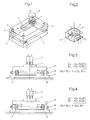
- FIG. 1 which represents the state of the art, four multicomponent load cells A are arranged between a base plate 1 and a cover plate 2 under prestress.
- the preload is generated by preload screws 3 which pass through the cover plate 2 and the measuring cells A and are screwed into the base plate 1.
- a workpiece 4 is mounted on the cover plate 2 and is machined by a tool 5, which is only indicated.
- a single force measuring cell A contains a plurality of piezoelectric sensor disks 6, at least one of which is sensitive to tension / pressure in the z-direction of a right-angled coordinate system and at least one is sensitive to thrust in the x and y directions.
- the measuring cell A contains a bore 7.
- the signal line connections on the measuring cell A for the signal components in the x, y and z directions are designated x, y, z.
- the two coordinate systems for the measuring arrangement and for the measuring cell are oriented identically, as a comparison of FIGS. 1 and 2 shows .
- the measuring arrangement is loaded with a temperature increase ⁇ T (FIG. 1) on the one hand and with a force F on the other hand, of which only the component Fz in the z direction is shown in FIG. 2.
- ⁇ T temperature increase
- F force on the other hand
- ⁇ l expansion
- the cover plate 2 is replaced by a T-shaped mounting platform 8 which is mounted in a U-shaped stand 9.
- the load cells A and B are no longer arranged horizontally, but between the vertical ones U legs of the stand 9 and the trunk of the T platform 8 clamped vertically.
- the pre-tensioning of the measuring cells A and B takes place by means of a single pre-tensioning screw 10 passing through the trunk of the platform 8 and extending through the platform 8 without any friction.
- the sensor disks 6 of the measuring cells A and B are arranged and oriented such that, on the one hand, the z direction of the sensor disks 6, which is determined by the direction of their tension / pressure sensitivity, runs in the direction of the preload screw 10 and, on the other hand, the tension / Pressure sensitivity for measuring cell A is opposite to that of measuring cell B.
- the coordinate system of the measuring cells is consequently rotated by 90 ° with respect to that of the measuring arrangement.
- a charge -Q z is generated as a function of the force 1/2 F T
- the charge + Q z is due to the opposite orientation / pressure sensitive sensor disc the charge + Q z, also as a function of 1/2 F T , occurs.
- FIG. 5 and 6 show in spatial representation, or in section, the structure of a dynamometer for the machining of workpieces.
- This dynamometer is characterized by an extremely low overall height H (Fig. 6).
- a very rigid mounting plate 11 serves on the one hand for receiving the workpiece 4 (FIG. 6) machined by the rotating, cutting tool 5 (FIG. 6) and on the other hand at the same time as a force introduction plate for the measuring cells A and B.
- These are in each case clamped in a vertical position between the end faces of the plate 11 and mounting blocks 12, the pretensioning in turn being applied by the continuous pretensioning screw 10.
- the pretensioning screws 10 are arranged in the axis 13 (FIG. 6) of the plate 11 which is neutral with respect to bending.
- the mounting blocks 12 have a number of bores 14 for the passage of clamping screws, not shown, with which the measuring arrangement itself can be mounted, for example, in a machine tool.
- the bores 14 are located as close as possible to the measuring cells A and B. As a result, the rigidity of the mounted measuring arrangement is as great as possible, which results in a high natural frequency of the system.
- FIG. 5 as shown in FIGS. 1 and 2, the two different coordinate systems are shown, namely the left above the mounting plate 11 relating to the entire measuring arrangement and the measuring cell-related in the left front or rear measuring cell A or B.
- the z-axes of the measuring cell-related coordinate system are directed towards one another with opposite signs.
- the signal lines 15 (FIG. 5) of the individual measuring cells are led to a common plug 16, from which they arrive as cables 17 to amplifiers and evaluation units, not shown.
- amplifiers and evaluation units in the mounting plate 11 and / or in one of the mounting blocks 12 in cavities 18 and 19, which are indicated by dashed lines in FIG. 5.
- the already amplified and processed signals are then passed on from these cavities 18 and 19, thereby increasing operational reliability the arrangement is increased.
- the exemplary embodiment according to FIG. 7 shows a rotating measuring arrangement which is mounted on the wheel hub of a vehicle for measuring the wheel forces and moments.
- a rim 21 of a motor vehicle wheel is connected via an intermediate ring 20 to a disk plate 22 designed as a force introduction platform.
- the measuring cells A and B rest on both sides of this disk plate 22, which in turn are clamped between the disk plate 22 and two force deflection plates 23 and 24 by means of the continuous preload screw 10.
- their sensor disks are oriented in such a way that their tension / pressure sensitivity runs in the direction of the preload screw 10, and that the measurement signals are caused by increases in temperature caused by the expansion of the disk plate 22 and the preload screw 10 in the measuring cells A and B cause charges, cancel each other out, while charges generated by unidirectional forces of both measuring cells A and B add to the desired measurement signal.
- the force deflection plates 23 and 24 are connected to a likewise disk-shaped holder 25.
Landscapes
- Physics & Mathematics (AREA)
- General Physics & Mathematics (AREA)
- Force Measurement Appropriate To Specific Purposes (AREA)
- Measuring Fluid Pressure (AREA)
- Hooks, Suction Cups, And Attachment By Adhesive Means (AREA)
- Telescopes (AREA)
- Measurement Of Force In General (AREA)
Applications Claiming Priority (3)
| Application Number | Priority Date | Filing Date | Title |
|---|---|---|---|
| CH1192/96 | 1996-05-09 | ||
| CH119296 | 1996-05-09 | ||
| CH01192/96A CH690865A5 (de) | 1996-05-09 | 1996-05-09 | Kraft- und Momentmessanordnung. |
Publications (3)
| Publication Number | Publication Date |
|---|---|
| EP0806643A2 true EP0806643A2 (fr) | 1997-11-12 |
| EP0806643A3 EP0806643A3 (fr) | 1998-04-22 |
| EP0806643B1 EP0806643B1 (fr) | 2003-11-12 |
Family
ID=4204659
Family Applications (1)
| Application Number | Title | Priority Date | Filing Date |
|---|---|---|---|
| EP97810192A Expired - Lifetime EP0806643B1 (fr) | 1996-05-09 | 1997-04-03 | Dispositif de mesure de la force et/ou du moment |
Country Status (6)
| Country | Link |
|---|---|
| US (1) | US5821432A (fr) |
| EP (1) | EP0806643B1 (fr) |
| JP (1) | JP3771354B2 (fr) |
| AT (1) | ATE254278T1 (fr) |
| CH (1) | CH690865A5 (fr) |
| DE (1) | DE59710976D1 (fr) |
Cited By (3)
| Publication number | Priority date | Publication date | Assignee | Title |
|---|---|---|---|---|
| WO2017036671A1 (fr) * | 2015-09-04 | 2017-03-09 | Kistler Holding Ag | Dispositif de détection de force et de moment |
| DE102016116180B4 (de) | 2016-08-01 | 2019-03-28 | Nuton GmbH | Verfahren und Kraftmessplatte zur mehrachsigen Erfassung einwirkender Kräfte und Momente |
| DE102018102327A1 (de) | 2018-02-01 | 2019-08-01 | Nuton GmbH | Kraftmesseinrichtung zur Erfassung von Bearbeitungskräften an einer Werkzeugmaschine sowie Werkzeugmaschine mit Kraftmesseinrichtung |
Families Citing this family (34)
| Publication number | Priority date | Publication date | Assignee | Title |
|---|---|---|---|---|
| US6760463B2 (en) * | 1995-05-08 | 2004-07-06 | Digimarc Corporation | Watermarking methods and media |
| US6119530A (en) * | 1998-03-09 | 2000-09-19 | Biomotions, Inc. | Force sensing device |
| JP3685475B2 (ja) * | 1998-03-26 | 2005-08-17 | タカタ株式会社 | シート重量計測装置 |
| US6389883B1 (en) * | 1999-10-19 | 2002-05-21 | Bertec Corporation | Device, system, and method for measurement of balance, stability, and tremor |
| US6810747B2 (en) * | 2000-02-07 | 2004-11-02 | Kistler Holding Ag | Test device for determining the friction and prestress values of screwed connections |
| JP2002056510A (ja) * | 2000-08-07 | 2002-02-22 | Matsushita Electric Ind Co Ltd | シールド型磁気ヘッド並びに磁気再生装置 |
| ES2629101T3 (es) * | 2008-05-05 | 2017-08-07 | Kistler Holding Ag | Célula de carga |
| US8490500B2 (en) * | 2010-11-16 | 2013-07-23 | Caterpillar Inc. | Torque coefficient measuring device |
| RU2475842C1 (ru) * | 2011-10-21 | 2013-02-20 | Федеральное государственное бюджетное образовательное учреждение высшего профессионального образования "Юго-Западный государственный университет" (ЮЗГУ) | Цифровой многокомпонентный датчик перемещений |
| JP5880935B2 (ja) * | 2011-12-20 | 2016-03-09 | セイコーエプソン株式会社 | センサーデバイス、センサーモジュール、ロボット、センサーデバイスの製造方法 |
| US8726740B1 (en) * | 2012-12-13 | 2014-05-20 | King Fahd University Of Petroleum And Minerals | Multi-axis dynamometer |
| JP6241204B2 (ja) * | 2013-10-31 | 2017-12-06 | セイコーエプソン株式会社 | 力検出装置およびロボット |
| CN104596675B (zh) | 2013-10-31 | 2019-05-14 | 精工爱普生株式会社 | 传感器元件、力检测装置、机器人、电子部件输送装置 |
| CN104596676B (zh) * | 2013-10-31 | 2019-03-26 | 精工爱普生株式会社 | 力检测装置、机器人、电子部件输送装置及检查装置 |
| JP6232943B2 (ja) * | 2013-11-05 | 2017-11-22 | セイコーエプソン株式会社 | 力検出装置、ロボットおよび電子部品搬送装置 |
| JP6232942B2 (ja) * | 2013-11-05 | 2017-11-22 | セイコーエプソン株式会社 | 力検出装置、ロボットおよび電子部品搬送装置 |
| CN110057484B (zh) * | 2013-11-05 | 2021-05-04 | 精工爱普生株式会社 | 力检测装置、机器人以及电子部件输送装置 |
| JP6476730B2 (ja) * | 2014-10-21 | 2019-03-06 | セイコーエプソン株式会社 | 力検出装置及びロボット |
| CN104634498B (zh) * | 2015-01-23 | 2017-03-15 | 重庆大学 | 基于关节力的空间六维力测量方法 |
| CN105865670B (zh) | 2015-02-09 | 2020-09-25 | 精工爱普生株式会社 | 力检测装置以及机器人 |
| CN105651447B (zh) * | 2016-03-28 | 2018-06-19 | 西南交通大学 | 一种用于划痕试验仪器的二向力测量装置 |
| JP2018119923A (ja) * | 2017-01-27 | 2018-08-02 | セイコーエプソン株式会社 | 力検出装置およびロボット |
| JP2018189385A (ja) | 2017-04-28 | 2018-11-29 | セイコーエプソン株式会社 | 力検出装置およびロボット |
| DE102018114899B4 (de) | 2017-06-20 | 2022-03-31 | Nuton GmbH | Verfahren zur Ermittlung der Geometrie oder relativen Position eines in das für die Aufnahme von Bearbeitungswerkzeugen vorgesehene Wechselspannsystem einer Werkzeugmaschine eingespannten Tastkörpers sowie entsprechend eingerichtete Werkzeugmaschine |
| JP2019012012A (ja) * | 2017-06-30 | 2019-01-24 | セイコーエプソン株式会社 | 力検出装置およびロボット |
| JP2019012013A (ja) | 2017-06-30 | 2019-01-24 | セイコーエプソン株式会社 | 力検出装置およびロボット |
| JP6432647B2 (ja) * | 2017-07-10 | 2018-12-05 | セイコーエプソン株式会社 | センサー素子、力検出装置およびロボット |
| CN109783975B (zh) * | 2019-01-31 | 2021-05-11 | 大连理工大学 | 基于热误差和温升加权的丝杠预紧量确定方法 |
| JP6941402B1 (ja) * | 2019-02-13 | 2021-09-29 | 株式会社トライフォース・マネジメント | 力覚センサ |
| JP2020163548A (ja) * | 2019-03-29 | 2020-10-08 | セイコーエプソン株式会社 | 水平多関節ロボットおよびロボットシステム |
| JP7207094B2 (ja) * | 2019-03-29 | 2023-01-18 | セイコーエプソン株式会社 | 水平多関節ロボット |
| CN110186597A (zh) * | 2019-05-14 | 2019-08-30 | 大连理工大学 | 一种侧面布置压电传感器的测力仪结构 |
| TWI716239B (zh) | 2019-12-26 | 2021-01-11 | 財團法人工業技術研究院 | 一種可感測低頻力與高頻力的力感測裝置 |
| CN112284601B (zh) * | 2020-10-23 | 2021-12-14 | 吉林大学 | 组合式六分力传感器及六分力测量方法 |
Citations (7)
| Publication number | Priority date | Publication date | Assignee | Title |
|---|---|---|---|---|
| DE1952522A1 (de) * | 1968-11-04 | 1970-11-12 | Kistler Instrumente Ag | Mehrkomponenten- Kraft- und Momentenmessanordnung |
| WO1985003479A1 (fr) * | 1984-01-31 | 1985-08-15 | Slim Borgudd | Dispositif ayant la forme d'un capteur pour mesurer des charges statiques, des charges dynamiques et des couples dans les trois axes x-y-z |
| JPS61111435A (ja) * | 1984-11-05 | 1986-05-29 | Fujitsu Ltd | 衝撃記録装置 |
| JPS63243828A (ja) * | 1987-03-31 | 1988-10-11 | Ngk Spark Plug Co Ltd | 回転軸のトルク検出装置 |
| US5165205A (en) * | 1987-06-24 | 1992-11-24 | Research Development Corporation Of Japan | Device for vibrating materials to be ground |
| EP0594534A1 (fr) * | 1992-10-23 | 1994-04-27 | K.K. Holding Ag | Mesure de plusieurs composantes de force et de moment |
| DE4336773A1 (de) * | 1993-10-28 | 1995-05-04 | Bosch Gmbh Robert | Einrichtung zum Messen von Drücken, Kräften und Momenten |
Family Cites Families (10)
| Publication number | Priority date | Publication date | Assignee | Title |
|---|---|---|---|---|
| US3210993A (en) * | 1961-10-27 | 1965-10-12 | Endevco Corp | Electromechanical transducer utilizing poisson ratio effects |
| US4313341A (en) * | 1978-12-07 | 1982-02-02 | Nippon Soken, Inc. | Torque detecting system for internal combustion engine |
| US4348908A (en) * | 1981-01-19 | 1982-09-14 | Branson Ultrasonics Corporation | Power measuring arrangement for vibratory welder |
| DE3151669C2 (de) * | 1981-12-28 | 1989-10-12 | Deutsche Forschungs- und Versuchsanstalt für Luft- und Raumfahrt e.V., 5000 Köln | Heckstielwaage zur Luftkraftbestimmung an Windkanalmodellen |
| SE8400484D0 (sv) * | 1984-01-31 | 1984-01-31 | Slim Borgudd | Anordning for metning av dynamisk och statisk lastpakenning vid en draganordning for t ex drivorgan |
| ATE47227T1 (de) * | 1986-03-18 | 1989-10-15 | Kristal Instr Ag | Piezoresistives kraftmesselement sowie dessen verwendung zur ermittlung von auf ein bauteil einwirkenden kraeften. |
| US4821584A (en) * | 1988-03-15 | 1989-04-18 | The United States Of America As Represented By The United States Department Of Energy | Piezoelectric film load cell robot collision detector |
| US5036240A (en) * | 1988-07-18 | 1991-07-30 | Lew Hyok S | Impulse sensor with mechanical preamplification and noise cancellation |
| CH680689A5 (fr) * | 1990-05-31 | 1992-10-15 | Kistler Instrumente Ag | |
| CH680752A5 (fr) * | 1990-05-31 | 1992-10-30 | Kistler Instrumente Ag |
-
1996
- 1996-05-09 CH CH01192/96A patent/CH690865A5/de not_active IP Right Cessation
-
1997
- 1997-04-03 DE DE59710976T patent/DE59710976D1/de not_active Expired - Lifetime
- 1997-04-03 EP EP97810192A patent/EP0806643B1/fr not_active Expired - Lifetime
- 1997-04-03 AT AT97810192T patent/ATE254278T1/de active
- 1997-04-16 US US08/839,884 patent/US5821432A/en not_active Expired - Lifetime
- 1997-05-08 JP JP11777497A patent/JP3771354B2/ja not_active Expired - Fee Related
Patent Citations (7)
| Publication number | Priority date | Publication date | Assignee | Title |
|---|---|---|---|---|
| DE1952522A1 (de) * | 1968-11-04 | 1970-11-12 | Kistler Instrumente Ag | Mehrkomponenten- Kraft- und Momentenmessanordnung |
| WO1985003479A1 (fr) * | 1984-01-31 | 1985-08-15 | Slim Borgudd | Dispositif ayant la forme d'un capteur pour mesurer des charges statiques, des charges dynamiques et des couples dans les trois axes x-y-z |
| JPS61111435A (ja) * | 1984-11-05 | 1986-05-29 | Fujitsu Ltd | 衝撃記録装置 |
| JPS63243828A (ja) * | 1987-03-31 | 1988-10-11 | Ngk Spark Plug Co Ltd | 回転軸のトルク検出装置 |
| US5165205A (en) * | 1987-06-24 | 1992-11-24 | Research Development Corporation Of Japan | Device for vibrating materials to be ground |
| EP0594534A1 (fr) * | 1992-10-23 | 1994-04-27 | K.K. Holding Ag | Mesure de plusieurs composantes de force et de moment |
| DE4336773A1 (de) * | 1993-10-28 | 1995-05-04 | Bosch Gmbh Robert | Einrichtung zum Messen von Drücken, Kräften und Momenten |
Non-Patent Citations (2)
| Title |
|---|
| PATENT ABSTRACTS OF JAPAN vol. 010, no. 294 (P-504), 7.Oktober 1986 & JP 61 111435 A (FUJITSU LTD), 29.Mai 1986, * |
| PATENT ABSTRACTS OF JAPAN vol. 013, no. 050 (P-823), 6.Februar 1989 & JP 63 243828 A (NGK SPARK PLUG CO LTD), 11.Oktober 1988, * |
Cited By (4)
| Publication number | Priority date | Publication date | Assignee | Title |
|---|---|---|---|---|
| WO2017036671A1 (fr) * | 2015-09-04 | 2017-03-09 | Kistler Holding Ag | Dispositif de détection de force et de moment |
| US10254183B2 (en) | 2015-09-04 | 2019-04-09 | Kistler Holding Ag | Device for detecting force and torque including multiple piezoelectric force measuring cells mechanically biased in a horizontal plane |
| DE102016116180B4 (de) | 2016-08-01 | 2019-03-28 | Nuton GmbH | Verfahren und Kraftmessplatte zur mehrachsigen Erfassung einwirkender Kräfte und Momente |
| DE102018102327A1 (de) | 2018-02-01 | 2019-08-01 | Nuton GmbH | Kraftmesseinrichtung zur Erfassung von Bearbeitungskräften an einer Werkzeugmaschine sowie Werkzeugmaschine mit Kraftmesseinrichtung |
Also Published As
| Publication number | Publication date |
|---|---|
| ATE254278T1 (de) | 2003-11-15 |
| DE59710976D1 (de) | 2003-12-18 |
| CH690865A5 (de) | 2001-02-15 |
| JPH1068665A (ja) | 1998-03-10 |
| JP3771354B2 (ja) | 2006-04-26 |
| EP0806643B1 (fr) | 2003-11-12 |
| EP0806643A3 (fr) | 1998-04-22 |
| US5821432A (en) | 1998-10-13 |
Similar Documents
| Publication | Publication Date | Title |
|---|---|---|
| EP0806643B1 (fr) | Dispositif de mesure de la force et/ou du moment | |
| DE6940548U (de) | Mehrkomponenten- kraft- und momentenmessanordnung | |
| EP1590641B1 (fr) | Capteur de mesure avec dispositif de precontrainte | |
| DE2038771A1 (de) | Druck-Messwertwandler | |
| DE3213319A1 (de) | Einrichtung zum messen von kraft- und momentkomponenten in mehreren richtungen | |
| WO2006042537A1 (fr) | Systeme dynamometrique comprenant au moins une articulation a rotule | |
| DE112020001152T5 (de) | Kraft-/drehmomentsensor mit schlangen- oder spiralförmigen verformbaren trägern und überlastträgern | |
| EP0594534A1 (fr) | Mesure de plusieurs composantes de force et de moment | |
| WO2019144171A9 (fr) | Système de mesure et procédé permettant de déterminer une force et/ou un couple au niveau d'un arbre de transmission de couple | |
| DE102020114431A1 (de) | Werkzeughalter und Verfahren zur Drehbearbeitung eines Werkstücks | |
| EP1370842A1 (fr) | Module de torsion d'un dispositif de detection de couple | |
| DE102016215083A1 (de) | Vorrichtung und Verfahren zum Überwachen zumindest einer Fahrwerkskomponente | |
| DE3342817C2 (de) | Meßnabe | |
| DE3019751C2 (de) | Einrichtung zur Messung der Schnittkraft von Schneidwerkzeugen eines Mehrfachwerkzeugträgers | |
| EP0686839A2 (fr) | Attelage de remorque avec capteur de force | |
| EP0338325A1 (fr) | Dispositif de mesure de force du type d'anneau à torsion | |
| DE69629340T2 (de) | Wandler zum messen der torsion zwischen zwei gekoppelten mechanischen teilen und verfahren zur fertigung des wandlers | |
| DE69531656T2 (de) | Verfahren zur Messung von mechanischen Spannungen in Fahrzeugen | |
| DE102014222708A1 (de) | Aktiver Wankstabilisator mit Sensor | |
| DE3540954C2 (fr) | ||
| DE3818126A1 (de) | Kraftmesseinrichtung | |
| EP0850400A1 (fr) | Transducteur de traction-compression, notamment pour systemes de freinage electromecaniques | |
| EP0603494A2 (fr) | Dispositif de mesure de force | |
| DE102006034481A1 (de) | Messeinrichtung | |
| WO2019081712A1 (fr) | Dispositif de mesure d'allongement |
Legal Events
| Date | Code | Title | Description |
|---|---|---|---|
| PUAI | Public reference made under article 153(3) epc to a published international application that has entered the european phase |
Free format text: ORIGINAL CODE: 0009012 |
|
| AK | Designated contracting states |
Kind code of ref document: A2 Designated state(s): AT DE GB |
|
| PUAL | Search report despatched |
Free format text: ORIGINAL CODE: 0009013 |
|
| AK | Designated contracting states |
Kind code of ref document: A3 Designated state(s): AT DE GB |
|
| 17P | Request for examination filed |
Effective date: 19981006 |
|
| 17Q | First examination report despatched |
Effective date: 20021216 |
|
| GRAH | Despatch of communication of intention to grant a patent |
Free format text: ORIGINAL CODE: EPIDOS IGRA |
|
| GRAS | Grant fee paid |
Free format text: ORIGINAL CODE: EPIDOSNIGR3 |
|
| GRAA | (expected) grant |
Free format text: ORIGINAL CODE: 0009210 |
|
| RAP1 | Party data changed (applicant data changed or rights of an application transferred) |
Owner name: KISTLER HOLDING AG |
|
| AK | Designated contracting states |
Kind code of ref document: B1 Designated state(s): AT DE GB |
|
| REG | Reference to a national code |
Ref country code: GB Ref legal event code: FG4D Free format text: NOT ENGLISH |
|
| GBT | Gb: translation of ep patent filed (gb section 77(6)(a)/1977) |
Effective date: 20031112 |
|
| REF | Corresponds to: |
Ref document number: 59710976 Country of ref document: DE Date of ref document: 20031218 Kind code of ref document: P |
|
| PLBE | No opposition filed within time limit |
Free format text: ORIGINAL CODE: 0009261 |
|
| STAA | Information on the status of an ep patent application or granted ep patent |
Free format text: STATUS: NO OPPOSITION FILED WITHIN TIME LIMIT |
|
| 26N | No opposition filed |
Effective date: 20040813 |
|
| PGFP | Annual fee paid to national office [announced via postgrant information from national office to epo] |
Ref country code: GB Payment date: 20150420 Year of fee payment: 19 Ref country code: DE Payment date: 20150421 Year of fee payment: 19 |
|
| PGFP | Annual fee paid to national office [announced via postgrant information from national office to epo] |
Ref country code: AT Payment date: 20150421 Year of fee payment: 19 |
|
| REG | Reference to a national code |
Ref country code: DE Ref legal event code: R119 Ref document number: 59710976 Country of ref document: DE |
|
| REG | Reference to a national code |
Ref country code: AT Ref legal event code: MM01 Ref document number: 254278 Country of ref document: AT Kind code of ref document: T Effective date: 20160403 |
|
| GBPC | Gb: european patent ceased through non-payment of renewal fee |
Effective date: 20160403 |
|
| PG25 | Lapsed in a contracting state [announced via postgrant information from national office to epo] |
Ref country code: DE Free format text: LAPSE BECAUSE OF NON-PAYMENT OF DUE FEES Effective date: 20161101 Ref country code: GB Free format text: LAPSE BECAUSE OF NON-PAYMENT OF DUE FEES Effective date: 20160403 |
|
| PG25 | Lapsed in a contracting state [announced via postgrant information from national office to epo] |
Ref country code: AT Free format text: LAPSE BECAUSE OF NON-PAYMENT OF DUE FEES Effective date: 20160403 |