JP2018119923A - 力検出装置およびロボット - Google Patents
力検出装置およびロボット Download PDFInfo
- Publication number
- JP2018119923A JP2018119923A JP2017013481A JP2017013481A JP2018119923A JP 2018119923 A JP2018119923 A JP 2018119923A JP 2017013481 A JP2017013481 A JP 2017013481A JP 2017013481 A JP2017013481 A JP 2017013481A JP 2018119923 A JP2018119923 A JP 2018119923A
- Authority
- JP
- Japan
- Prior art keywords
- force detection
- detection device
- force
- axis
- arm
- Prior art date
- Legal status (The legal status is an assumption and is not a legal conclusion. Google has not performed a legal analysis and makes no representation as to the accuracy of the status listed.)
- Pending
Links
- 238000001514 detection method Methods 0.000 claims description 252
- 239000012636 effector Substances 0.000 claims description 70
- 239000010453 quartz Substances 0.000 claims description 15
- VYPSYNLAJGMNEJ-UHFFFAOYSA-N silicon dioxide Inorganic materials O=[Si]=O VYPSYNLAJGMNEJ-UHFFFAOYSA-N 0.000 claims description 15
- 239000000463 material Substances 0.000 description 18
- 239000000470 constituent Substances 0.000 description 12
- 238000010586 diagram Methods 0.000 description 11
- 239000000758 substrate Substances 0.000 description 11
- 239000013078 crystal Substances 0.000 description 9
- 239000007769 metal material Substances 0.000 description 7
- 238000000926 separation method Methods 0.000 description 6
- 230000007423 decrease Effects 0.000 description 5
- 229910052782 aluminium Inorganic materials 0.000 description 4
- XAGFODPZIPBFFR-UHFFFAOYSA-N aluminium Chemical compound [Al] XAGFODPZIPBFFR-UHFFFAOYSA-N 0.000 description 4
- 239000000919 ceramic Substances 0.000 description 4
- 230000035945 sensitivity Effects 0.000 description 4
- 230000000694 effects Effects 0.000 description 3
- 238000010008 shearing Methods 0.000 description 3
- 239000010935 stainless steel Substances 0.000 description 3
- 229910001220 stainless steel Inorganic materials 0.000 description 3
- 230000009466 transformation Effects 0.000 description 3
- 239000013585 weight reducing agent Substances 0.000 description 3
- XEEYBQQBJWHFJM-UHFFFAOYSA-N Iron Chemical compound [Fe] XEEYBQQBJWHFJM-UHFFFAOYSA-N 0.000 description 2
- PXHVJJICTQNCMI-UHFFFAOYSA-N Nickel Chemical compound [Ni] PXHVJJICTQNCMI-UHFFFAOYSA-N 0.000 description 2
- 229910045601 alloy Inorganic materials 0.000 description 2
- 239000000956 alloy Substances 0.000 description 2
- 230000008859 change Effects 0.000 description 2
- 230000001276 controlling effect Effects 0.000 description 2
- 238000006073 displacement reaction Methods 0.000 description 2
- 229910000833 kovar Inorganic materials 0.000 description 2
- 229910052451 lead zirconate titanate Inorganic materials 0.000 description 2
- 230000001105 regulatory effect Effects 0.000 description 2
- 230000004044 response Effects 0.000 description 2
- 239000010936 titanium Substances 0.000 description 2
- 229910052719 titanium Inorganic materials 0.000 description 2
- WKBPZYKAUNRMKP-UHFFFAOYSA-N 1-[2-(2,4-dichlorophenyl)pentyl]1,2,4-triazole Chemical compound C=1C=C(Cl)C=C(Cl)C=1C(CCC)CN1C=NC=N1 WKBPZYKAUNRMKP-UHFFFAOYSA-N 0.000 description 1
- WSMQKESQZFQMFW-UHFFFAOYSA-N 5-methyl-pyrazole-3-carboxylic acid Chemical compound CC1=CC(C(O)=O)=NN1 WSMQKESQZFQMFW-UHFFFAOYSA-N 0.000 description 1
- VYZAMTAEIAYCRO-UHFFFAOYSA-N Chromium Chemical compound [Cr] VYZAMTAEIAYCRO-UHFFFAOYSA-N 0.000 description 1
- RYGMFSIKBFXOCR-UHFFFAOYSA-N Copper Chemical compound [Cu] RYGMFSIKBFXOCR-UHFFFAOYSA-N 0.000 description 1
- 229910017709 Ni Co Inorganic materials 0.000 description 1
- 229910003267 Ni-Co Inorganic materials 0.000 description 1
- 229910003262 Ni‐Co Inorganic materials 0.000 description 1
- BQCADISMDOOEFD-UHFFFAOYSA-N Silver Chemical compound [Ag] BQCADISMDOOEFD-UHFFFAOYSA-N 0.000 description 1
- RTAQQCXQSZGOHL-UHFFFAOYSA-N Titanium Chemical compound [Ti] RTAQQCXQSZGOHL-UHFFFAOYSA-N 0.000 description 1
- 238000013459 approach Methods 0.000 description 1
- 229910002113 barium titanate Inorganic materials 0.000 description 1
- JRPBQTZRNDNNOP-UHFFFAOYSA-N barium titanate Chemical compound [Ba+2].[Ba+2].[O-][Ti]([O-])([O-])[O-] JRPBQTZRNDNNOP-UHFFFAOYSA-N 0.000 description 1
- 230000008901 benefit Effects 0.000 description 1
- 239000003990 capacitor Substances 0.000 description 1
- 238000006243 chemical reaction Methods 0.000 description 1
- 229910052804 chromium Inorganic materials 0.000 description 1
- 239000011651 chromium Substances 0.000 description 1
- 230000006835 compression Effects 0.000 description 1
- 238000007906 compression Methods 0.000 description 1
- 229910052802 copper Inorganic materials 0.000 description 1
- 239000010949 copper Substances 0.000 description 1
- NKZSPGSOXYXWQA-UHFFFAOYSA-N dioxido(oxo)titanium;lead(2+) Chemical compound [Pb+2].[O-][Ti]([O-])=O NKZSPGSOXYXWQA-UHFFFAOYSA-N 0.000 description 1
- 230000001747 exhibiting effect Effects 0.000 description 1
- PCHJSUWPFVWCPO-UHFFFAOYSA-N gold Chemical compound [Au] PCHJSUWPFVWCPO-UHFFFAOYSA-N 0.000 description 1
- 229910052737 gold Inorganic materials 0.000 description 1
- 239000010931 gold Substances 0.000 description 1
- 238000009434 installation Methods 0.000 description 1
- 229910052742 iron Inorganic materials 0.000 description 1
- HFGPZNIAWCZYJU-UHFFFAOYSA-N lead zirconate titanate Chemical compound [O-2].[O-2].[O-2].[O-2].[O-2].[Ti+4].[Zr+4].[Pb+2] HFGPZNIAWCZYJU-UHFFFAOYSA-N 0.000 description 1
- GQYHUHYESMUTHG-UHFFFAOYSA-N lithium niobate Chemical compound [Li+].[O-][Nb](=O)=O GQYHUHYESMUTHG-UHFFFAOYSA-N 0.000 description 1
- 229910052759 nickel Inorganic materials 0.000 description 1
- 230000002093 peripheral effect Effects 0.000 description 1
- 229910052709 silver Inorganic materials 0.000 description 1
- 239000004332 silver Substances 0.000 description 1
- 239000011031 topaz Substances 0.000 description 1
- 229910052853 topaz Inorganic materials 0.000 description 1
- 238000011426 transformation method Methods 0.000 description 1
- 229910052726 zirconium Inorganic materials 0.000 description 1
Images


Classifications
-
- G—PHYSICS
- G01—MEASURING; TESTING
- G01L—MEASURING FORCE, STRESS, TORQUE, WORK, MECHANICAL POWER, MECHANICAL EFFICIENCY, OR FLUID PRESSURE
- G01L1/00—Measuring force or stress, in general
- G01L1/16—Measuring force or stress, in general using properties of piezoelectric devices
-
- B—PERFORMING OPERATIONS; TRANSPORTING
- B25—HAND TOOLS; PORTABLE POWER-DRIVEN TOOLS; MANIPULATORS
- B25J—MANIPULATORS; CHAMBERS PROVIDED WITH MANIPULATION DEVICES
- B25J13/00—Controls for manipulators
- B25J13/08—Controls for manipulators by means of sensing devices, e.g. viewing or touching devices
- B25J13/085—Force or torque sensors
-
- G—PHYSICS
- G01—MEASURING; TESTING
- G01L—MEASURING FORCE, STRESS, TORQUE, WORK, MECHANICAL POWER, MECHANICAL EFFICIENCY, OR FLUID PRESSURE
- G01L5/00—Apparatus for, or methods of, measuring force, work, mechanical power, or torque, specially adapted for specific purposes
- G01L5/0061—Force sensors associated with industrial machines or actuators
-
- G—PHYSICS
- G01—MEASURING; TESTING
- G01L—MEASURING FORCE, STRESS, TORQUE, WORK, MECHANICAL POWER, MECHANICAL EFFICIENCY, OR FLUID PRESSURE
- G01L5/00—Apparatus for, or methods of, measuring force, work, mechanical power, or torque, specially adapted for specific purposes
- G01L5/16—Apparatus for, or methods of, measuring force, work, mechanical power, or torque, specially adapted for specific purposes for measuring several components of force
- G01L5/166—Apparatus for, or methods of, measuring force, work, mechanical power, or torque, specially adapted for specific purposes for measuring several components of force using photoelectric means
-
- G—PHYSICS
- G01—MEASURING; TESTING
- G01L—MEASURING FORCE, STRESS, TORQUE, WORK, MECHANICAL POWER, MECHANICAL EFFICIENCY, OR FLUID PRESSURE
- G01L5/00—Apparatus for, or methods of, measuring force, work, mechanical power, or torque, specially adapted for specific purposes
- G01L5/22—Apparatus for, or methods of, measuring force, work, mechanical power, or torque, specially adapted for specific purposes for measuring the force applied to control members, e.g. control members of vehicles, triggers
- G01L5/226—Apparatus for, or methods of, measuring force, work, mechanical power, or torque, specially adapted for specific purposes for measuring the force applied to control members, e.g. control members of vehicles, triggers to manipulators, e.g. the force due to gripping
-
- Y—GENERAL TAGGING OF NEW TECHNOLOGICAL DEVELOPMENTS; GENERAL TAGGING OF CROSS-SECTIONAL TECHNOLOGIES SPANNING OVER SEVERAL SECTIONS OF THE IPC; TECHNICAL SUBJECTS COVERED BY FORMER USPC CROSS-REFERENCE ART COLLECTIONS [XRACs] AND DIGESTS
- Y10—TECHNICAL SUBJECTS COVERED BY FORMER USPC
- Y10S—TECHNICAL SUBJECTS COVERED BY FORMER USPC CROSS-REFERENCE ART COLLECTIONS [XRACs] AND DIGESTS
- Y10S901/00—Robots
- Y10S901/46—Sensing device
Abstract
【解決手段】アームを有するロボットに取り付け可能な力検出装置であって、被取付部材を取り付け可能な取付面を有する凸部を備える第1部材と、前記アームに取り付けられる第2部材と、前記第1部材と前記第2部材との間に支持され、前記第1部材と前記第2部材とに加えられる外力を検出する少なくとも1つの圧電素子と、を備えることを特徴とする力検出装置。
【選択図】図3
Description
被取付部材を取り付け可能な取付面を有する凸部を備える第1部材と、
前記アームに取り付けられる第2部材と、
前記第1部材と前記第2部材との間に支持され、前記第1部材と前記第2部材とに加えられる外力を検出する少なくとも1つの圧電素子と、を備えることを特徴とする力検出装置。
これにより、力検出装置の高感度化を図ったり、検出軸の多軸化を図ったりすることができる。
前記取付面の法線方向から見て、前記凸部は、複数の前記センサーデバイスよりも内側に位置していることが好ましい。
前記第2部材は、前記圧電素子を与圧する第2与圧部を有することが好ましい。
これにより、高感度、広いダイナミックレンジ、高い剛性等の優れた特性を有する力検出装置を実現することができる。
≪ロボット≫
図1は、本発明の第1実施形態に係るロボットを示す斜視図である。なお、図1には、説明の便宜上、互いに直交する3つの軸としてα軸、β軸およびγ軸が図示されており、各軸を示す矢印の先端側を「+」、基端側を「−」とする。また、α軸に平行な方向を「α軸方向」、β軸に平行な方向を「β軸方向」、γ軸に平行な方向を「γ軸方向」という。また、+γ軸方向側を「上」、−γ軸方向側を「下」ともいう。また、γ軸方向から見たものを「平面視」という。また、図1中の基台110側を「基端」、その反対側(エンドエフェクター17側)を「先端」と言う。
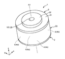
[力検出装置]
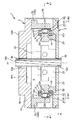
図2は、図1に示す力検出装置を示す斜視図である。図3は、図2に示す力検出装置の縦断面図である。図4は、図2に示す力検出装置の横断面図である。図5は、図3および図4に示す力検出装置が備える力検出素子の断面図である。なお、図3は、図4中のA2−A2線断面図であり、図4は、図3中のA1−A1線断面図である。また、図2および図4には、説明の便宜上、互いに直交する3つの軸としてx軸、y軸およびz軸が図示されており、各軸を示す矢印の先端側を「+」、基端側を「−」とする。また、x軸に平行な方向を「x軸方向」、y軸に平行な方向を「y軸方向」、z軸に平行な方向を「z軸方向」という。また、+z軸方向側を「上」、−z軸方向側を「下」ともいう。また、z軸方向から見たものを「平面視」という。
[第1部材]
図3に示すように、第1部材3は、天板31(第1基部)と、天板31の上部側の中央部に設けられた凸部32と、天板31の下部側でかつ外周部に設けられた複数の壁部33(第1与圧部)と、を有する。なお、以下の説明では、4つの壁部33のうち、図4中の上側に位置する壁部33を「壁部33a」といい、以降時計回りに順に「壁部33b」、「壁部33c」および「壁部33d」という。また、各壁部33a、33b、33c、33dを区別しない場合は、それらを「壁部33」という。この第1部材3の平面視での外形は、図2に示すように円形であるが、これに限定されず、例えば、四角形、五角形等の多角形、楕円形等であってもよい。また、第1部材3は、その中央部に中心軸A1に沿って形成された貫通孔35を有する。この貫通孔35は、凸部32をその中央部において貫通している。
図3に示すように、第2部材2は、底板21(第2基部)と、底板21の上部側に設けられた複数の壁部22(第2与圧部)と、を有する。この第2部材2の平面視での外形は、図2に示すように円形であるが、これに限定されず、例えば、四角形、五角形等の多角形、楕円形等であってもよい。また、図3に示すように、第2部材2は、その中央部に中心軸A1に沿って形成された貫通孔25を有する。
図2に示すように、側壁部20は、円筒状をなしており、その上端部および下端部がそれぞれ第1部材3および第2部材2に対して例えばネジ止め、嵌合等によって固定されている。また、図3に示すように、側壁部20と前述した第1部材3の天板31と第2部材2の底板21とで囲まれた空間S、すなわち力検出装置1の内部空間に、複数のセンサーデバイス4が収納されている。
各センサーデバイス4は、図3に示すように、力検出素子41と、力検出素子41を収納するパッケージ42と、を有している。各センサーデバイス4は、第1部材3の壁部33と第2部材2の壁部22との間に配置されている。力検出素子41は、少なくとも1つの(複数の)圧電素子5を備えている。
パッケージ42は、力検出素子41が設置されている凹部をその内側に有する基部421と、その基部421に接合されている蓋体422と、を有し、基部421の凹部が蓋体422により封止されている。これにより、力検出素子41を保護することができる。ここで、基部421は、前述した第2部材2の頂面231に当接している。一方、蓋体422は、前述した第1部材3の内壁面331に当接している。
図5に示す力検出素子41は、力検出素子41に加えられた外力のX軸方向の成分に応じた電荷QX、力検出素子41に加えられた外力のY軸方向の成分に応じた電荷QY、および、力検出素子41に加えられた外力のZ軸方向の成分に応じた電荷QZを出力する機能を有する。この力検出素子41は、X軸に平行な外力(せん断力)に応じて電荷QXを出力する圧電素子5aと、Z軸に平行な外力(圧縮/引張力)に応じて電荷QZを出力する圧電素子5bと、Y軸に平行な外力(せん断力)に応じて電荷QYを出力する圧電素子5cと、基準電位、例えばグランド電位(GND)に電気的に接続されているグランド電極層54、55、56、57と、を有する。また、力検出素子41は、圧電素子5a、5b、5cおよびグランド電極層54、55、56、57を備える構造体50を支持する支持基板58、59(ダミー基材)を有する。ここで、支持基板58、グランド電極層54、圧電素子5a、グランド電極層55、圧電素子5b、グランド電極層56、圧電素子5c、グランド電極層57、支持基板59の順でこれらが積層されている。なお、以下では、圧電素子5a、5b、5cをそれぞれ「圧電素子5」ともいう。
複数の与圧ボルト51は、第1部材3の壁部33と第2部材2の壁部22とでセンサーデバイス4(より具体的には複数の圧電素子5)を挟んで与圧した状態で壁部33および壁部22を互いに固定している(図3および図4参照)。各与圧ボルト51は、壁部33側から壁部33の貫通孔37に挿通され、与圧ボルト51の先端部に形成された雄ネジを壁部22に形成された雌ネジに螺合されている。このような複数の与圧ボルト51により、第1部材3の内壁面331と第2部材2の頂面231とでセンサーデバイス4のパッケージ42を介して力検出素子41を挟んで与圧することができる。また、各与圧ボルト51の締結力を適宜調整することで、力検出素子41に対して、所定の大きさの圧電素子5の積層方向D1の圧力を与圧として加えることができる(図5参照)。
図3に示すように、アナログ回路基板6は、空間S、すなわち第1部材3と第2部材2との間に配置されている。このアナログ回路基板6には、第2部材2の突出した部分23が挿通されている貫通孔61と、各与圧ボルト51が挿通されている貫通孔62と、が形成されている(図3および図4参照)。アナログ回路基板6は、部分23に挿通された状態で、センサーデバイス4に対して中心軸A1側に配置されている。これにより、センサーデバイス4の近傍にアナログ回路基板6を設けることができ、センサーデバイス4からの配線長さを短くすることができる。そのため、構造の簡素化に寄与することができる。
デジタル回路基板は、図示しないが、例えば、第2部材2上に設けることができる。このデジタル回路基板は、前述したアナログ回路基板6に電気的に接続されている。デジタル回路基板は、図示しないが、アナログ回路基板6からの電圧VX、VY、VZに基づいて、外力を検出(演算)する外力検出回路を備えている。外力検出回路は、x軸方向の並進力成分Fx、y軸方向の並進力成分Fy、z軸方向の並進力成分Fz、X軸周りの回転力成分Mx、Y軸周りの回転力成分My、Z軸周りの回転力成分Mzを演算する。この外力検出回路は、例えば、ADコンバーターと、このADコンバーターに接続されたCPU等の演算回路と、を有して構成することができる。
図20は、本発明の第2実施形態に係るロボットが備える力検出装置を示す縦断面図である。なお、以下の説明では、第2実施形態に関し、前述した実施形態との相違点を中心に説明し、同様の事項に関してはその説明を省略する。また、図20において、前述した実施形態と同様の構成は、同一符号を付している。
図21は、本発明の第3実施形態に係るロボットを示す斜視図である。なお、以下の説明では、第2実施形態に関し、前述した実施形態との相違点を中心に説明し、同様の事項に関してはその説明を省略する。また、図20において、前述した実施形態と同様の構成は、同一符号を付している。
Claims (11)
- アームを有するロボットに取り付け可能な力検出装置であって、
被取付部材を取り付け可能な取付面を有する凸部を備える第1部材と、
前記アームに取り付けられる第2部材と、
前記第1部材と前記第2部材との間に支持され、前記第1部材と前記第2部材とに加えられる外力を検出する少なくとも1つの圧電素子と、を備えることを特徴とする力検出装置。 - 複数の前記圧電素子を備える請求項1に記載の力検出装置。
- 前記第1部材と前記第2部材とによって挟持され、少なくとも1つの前記圧電素子を備えるセンサーデバイスを複数有し、
前記取付面の法線方向から見て、前記凸部は、複数の前記センサーデバイスよりも内側に位置している請求項2に記載の力検出装置。 - 前記第1部材は、前記凸部とは反対側に凹部を有する請求項1ないし3のいずれか1項に記載の力検出装置。
- 前記第1部材は、前記圧電素子を与圧する第1与圧部を有し、
前記第2部材は、前記圧電素子を与圧する第2与圧部を有する請求項1ないし4のいずれか1項に記載の力検出装置。 - 前記圧電素子は、水晶を含む請求項1ないし5のいずれか1項に記載の力検出装置。
- 前記第1部材と前記第2部材とに開口した貫通孔を有する請求項1ないし6のいずれか1項に記載の力検出装置。
- 前記第2部材は、前記第2部材を前記アームに取り付ける取付部材を接続できるよう構成されている請求項1ないし7のいずれか1項に記載の力検出装置。
- 前記被取付部材は、エンドエフェクターである請求項1ないし8のいずれか1項に記載の力検出装置。
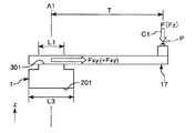
- 前記エンドエフェクターの作業箇所は、前記取付面の中心を通る前記取付面の法線に対してずれている請求項9に記載の力検出装置。
- 請求項1ないし10のいずれか1項に記載の力検出装置と、当該力検出装置が取り付けられたアームと、を有することを特徴とするロボット。
Priority Applications (4)
| Application Number | Priority Date | Filing Date | Title |
|---|---|---|---|
| JP2017013481A JP2018119923A (ja) | 2017-01-27 | 2017-01-27 | 力検出装置およびロボット |
| CN201810067000.1A CN108362409A (zh) | 2017-01-27 | 2018-01-23 | 力检测装置以及机器人 |
| US15/879,935 US10578500B2 (en) | 2017-01-27 | 2018-01-25 | Force detecting device and robot |
| JP2021037081A JP7022363B2 (ja) | 2017-01-27 | 2021-03-09 | 力検出装置およびロボットシステム |
Applications Claiming Priority (1)
| Application Number | Priority Date | Filing Date | Title |
|---|---|---|---|
| JP2017013481A JP2018119923A (ja) | 2017-01-27 | 2017-01-27 | 力検出装置およびロボット |
Related Child Applications (1)
| Application Number | Title | Priority Date | Filing Date |
|---|---|---|---|
| JP2021037081A Division JP7022363B2 (ja) | 2017-01-27 | 2021-03-09 | 力検出装置およびロボットシステム |
Publications (2)
| Publication Number | Publication Date |
|---|---|
| JP2018119923A true JP2018119923A (ja) | 2018-08-02 |
| JP2018119923A5 JP2018119923A5 (ja) | 2019-12-26 |
Family
ID=62977251
Family Applications (2)
| Application Number | Title | Priority Date | Filing Date |
|---|---|---|---|
| JP2017013481A Pending JP2018119923A (ja) | 2017-01-27 | 2017-01-27 | 力検出装置およびロボット |
| JP2021037081A Active JP7022363B2 (ja) | 2017-01-27 | 2021-03-09 | 力検出装置およびロボットシステム |
Family Applications After (1)
| Application Number | Title | Priority Date | Filing Date |
|---|---|---|---|
| JP2021037081A Active JP7022363B2 (ja) | 2017-01-27 | 2021-03-09 | 力検出装置およびロボットシステム |
Country Status (3)
| Country | Link |
|---|---|
| US (1) | US10578500B2 (ja) |
| JP (2) | JP2018119923A (ja) |
| CN (1) | CN108362409A (ja) |
Families Citing this family (8)
| Publication number | Priority date | Publication date | Assignee | Title |
|---|---|---|---|---|
| JP6746517B2 (ja) * | 2017-03-08 | 2020-08-26 | 日本電産コパル電子株式会社 | 力覚センサ |
| CN110274725A (zh) * | 2019-01-17 | 2019-09-24 | 上海肇擎传感技术有限公司 | 一种基于石英振梁的六轴力传感器敏感结构 |
| JP7207094B2 (ja) * | 2019-03-29 | 2023-01-18 | セイコーエプソン株式会社 | 水平多関節ロボット |
| JP2020163548A (ja) * | 2019-03-29 | 2020-10-08 | セイコーエプソン株式会社 | 水平多関節ロボットおよびロボットシステム |
| CN111129858A (zh) * | 2019-12-28 | 2020-05-08 | 深圳市优必选科技股份有限公司 | 一种磁吸式连接系统、模型搭建方法及机器人 |
| CN112077879B (zh) * | 2020-08-29 | 2021-12-03 | 上海大学 | 一种基于仿人柔软指的转轴全工作域力学性能检测方法 |
| CN112179553B (zh) * | 2020-09-09 | 2021-06-22 | 西南交通大学 | 一种超声同步测量螺栓轴向力和剪切力的方法 |
| CN114659697B (zh) * | 2022-03-28 | 2023-06-23 | 浙江机电职业技术学院 | 一种基于电容传感器的柔性六维力传感器 |
Citations (6)
| Publication number | Priority date | Publication date | Assignee | Title |
|---|---|---|---|---|
| US4640138A (en) * | 1985-03-06 | 1987-02-03 | Mts Systems Corporation | Multiple axis load sensitive transducer |
| JPS6321530A (ja) * | 1986-07-15 | 1988-01-29 | Ricoh Co Ltd | 力検出装置 |
| JP2012137421A (ja) * | 2010-12-27 | 2012-07-19 | Fanuc Ltd | 3軸力センサを用いて力制御をおこなうロボットの制御装置 |
| JP2015090295A (ja) * | 2013-11-05 | 2015-05-11 | セイコーエプソン株式会社 | 力検出装置、ロボットおよび電子部品搬送装置 |
| JP2016070824A (ja) * | 2014-09-30 | 2016-05-09 | ファナック株式会社 | 変位検出方式の6軸力センサ |
| JP2016161310A (ja) * | 2015-02-27 | 2016-09-05 | セイコーエプソン株式会社 | 力検出装置およびロボット |
Family Cites Families (28)
| Publication number | Priority date | Publication date | Assignee | Title |
|---|---|---|---|---|
| CA1054824A (en) * | 1975-09-23 | 1979-05-22 | Bendix Corporation (The) | Multi-axis load cell |
| US4138884A (en) * | 1977-04-20 | 1979-02-13 | The Bendix Corporation | Multi-axis load cell |
| US4573362A (en) * | 1984-07-09 | 1986-03-04 | Eaton Corporation | Multi-axis load transducer |
| US4911023A (en) * | 1986-07-15 | 1990-03-27 | Ricoh Company, Ltd. | Force sensing apparatus |
| US4836034A (en) * | 1986-07-15 | 1989-06-06 | Ricoh Company, Ltd. | Force sensing apparatus |
| US4821584A (en) * | 1988-03-15 | 1989-04-18 | The United States Of America As Represented By The United States Department Of Energy | Piezoelectric film load cell robot collision detector |
| JPH0577151A (ja) * | 1991-09-20 | 1993-03-30 | Hitachi Ltd | 多軸自由度装置 |
| JPH07136904A (ja) * | 1993-11-19 | 1995-05-30 | Hitachi Metals Ltd | バリ取りロボット制御方法 |
| CH690865A5 (de) * | 1996-05-09 | 2001-02-15 | Kk Holding Ag | Kraft- und Momentmessanordnung. |
| DE10034569B4 (de) * | 2000-07-14 | 2004-02-12 | Deutsches Zentrum für Luft- und Raumfahrt e.V. | Einrichtung zum Erfassen von Relativbewegungen eines Objekts |
| WO2002057731A1 (fr) * | 2001-01-22 | 2002-07-25 | K-Tech Devices Corp. | Capteur de contrainte |
| JP4203051B2 (ja) * | 2005-06-28 | 2008-12-24 | 本田技研工業株式会社 | 力覚センサ |
| JP5875382B2 (ja) * | 2011-02-15 | 2016-03-02 | キヤノン株式会社 | 力覚センサ、ロボット装置、ロボットハンド及び検出装置 |
| JP5821210B2 (ja) * | 2011-02-22 | 2015-11-24 | セイコーエプソン株式会社 | 水平多関節ロボット及び水平多関節ロボットの制御方法 |
| JP2013101020A (ja) * | 2011-11-08 | 2013-05-23 | Seiko Epson Corp | センサー素子、力検出装置およびロボット |
| JP5929271B2 (ja) * | 2012-02-07 | 2016-06-01 | セイコーエプソン株式会社 | ロボットハンドおよびロボット |
| JP5895615B2 (ja) * | 2012-03-09 | 2016-03-30 | セイコーエプソン株式会社 | センサーモジュール、力検出装置及びロボット |
| JP2015071214A (ja) | 2013-10-04 | 2015-04-16 | キヤノン株式会社 | 力覚センサ保護機構、エンドエフェクタ及びロボットアーム |
| CN104596675B (zh) * | 2013-10-31 | 2019-05-14 | 精工爱普生株式会社 | 传感器元件、力检测装置、机器人、电子部件输送装置 |
| US9705069B2 (en) * | 2013-10-31 | 2017-07-11 | Seiko Epson Corporation | Sensor device, force detecting device, robot, electronic component conveying apparatus, electronic component inspecting apparatus, and component machining apparatus |
| CN104614118B (zh) * | 2013-11-05 | 2019-01-11 | 精工爱普生株式会社 | 力检测装置、机器人以及电子部件输送装置 |
| JP6252241B2 (ja) * | 2014-02-27 | 2017-12-27 | セイコーエプソン株式会社 | 力検出装置、およびロボット |
| JP2015184005A (ja) * | 2014-03-20 | 2015-10-22 | セイコーエプソン株式会社 | 力検出装置、およびロボット |
| JP6476730B2 (ja) * | 2014-10-21 | 2019-03-06 | セイコーエプソン株式会社 | 力検出装置及びロボット |
| CN105865670B (zh) * | 2015-02-09 | 2020-09-25 | 精工爱普生株式会社 | 力检测装置以及机器人 |
| JP6541449B2 (ja) * | 2015-06-05 | 2019-07-10 | キヤノン株式会社 | 振動型駆動装置及び医用システム |
| US9841329B2 (en) * | 2015-06-08 | 2017-12-12 | Pioner Engineering Company | Strain gage based system and method for failure detection of a fluid film bearing |
| WO2017132696A1 (en) * | 2016-01-28 | 2017-08-03 | Transenterix Surgical, Inc. | Force estimation using robotic manipulator force torque sensors |
-
2017
- 2017-01-27 JP JP2017013481A patent/JP2018119923A/ja active Pending
-
2018
- 2018-01-23 CN CN201810067000.1A patent/CN108362409A/zh active Pending
- 2018-01-25 US US15/879,935 patent/US10578500B2/en active Active
-
2021
- 2021-03-09 JP JP2021037081A patent/JP7022363B2/ja active Active
Patent Citations (6)
| Publication number | Priority date | Publication date | Assignee | Title |
|---|---|---|---|---|
| US4640138A (en) * | 1985-03-06 | 1987-02-03 | Mts Systems Corporation | Multiple axis load sensitive transducer |
| JPS6321530A (ja) * | 1986-07-15 | 1988-01-29 | Ricoh Co Ltd | 力検出装置 |
| JP2012137421A (ja) * | 2010-12-27 | 2012-07-19 | Fanuc Ltd | 3軸力センサを用いて力制御をおこなうロボットの制御装置 |
| JP2015090295A (ja) * | 2013-11-05 | 2015-05-11 | セイコーエプソン株式会社 | 力検出装置、ロボットおよび電子部品搬送装置 |
| JP2016070824A (ja) * | 2014-09-30 | 2016-05-09 | ファナック株式会社 | 変位検出方式の6軸力センサ |
| JP2016161310A (ja) * | 2015-02-27 | 2016-09-05 | セイコーエプソン株式会社 | 力検出装置およびロボット |
Also Published As
| Publication number | Publication date |
|---|---|
| US20180217013A1 (en) | 2018-08-02 |
| JP2021096263A (ja) | 2021-06-24 |
| CN108362409A (zh) | 2018-08-03 |
| US10578500B2 (en) | 2020-03-03 |
| JP7022363B2 (ja) | 2022-02-18 |
Similar Documents
| Publication | Publication Date | Title |
|---|---|---|
| JP7022363B2 (ja) | 力検出装置およびロボットシステム | |
| JP6252241B2 (ja) | 力検出装置、およびロボット | |
| JP6163900B2 (ja) | 力検出装置およびロボット | |
| CN104596681B (zh) | 传感器设备、力检测装置、机器人、电子部件输送装置、电子部件检查装置及部件加工装置 | |
| US10661456B2 (en) | Force detection apparatus and robot | |
| JP2019027920A (ja) | 力検出装置およびロボット | |
| US10654179B2 (en) | Force detection apparatus and robot | |
| US20180283965A1 (en) | Force Detection Device And Robot | |
| JP2015087289A (ja) | センサー素子、力検出装置、ロボット、電子部品搬送装置、電子部品検査装置および部品加工装置 | |
| JP6248709B2 (ja) | 力検出装置およびロボット | |
| JP2018087781A (ja) | 力センサーおよびロボット | |
| JP6354894B2 (ja) | 力検出装置、およびロボット | |
| JP2014196922A (ja) | 力検出装置、ロボット、電子部品搬送装置、電子部品検査装置、部品加工装置および移動体 | |
| JP2015184007A (ja) | 力検出装置、ロボット、電子部品搬送装置および電子部品検出装置 | |
| JP6436261B2 (ja) | 力検出装置、およびロボット | |
| JP6477843B2 (ja) | 力検出装置、およびロボット | |
| JP2016161310A (ja) | 力検出装置およびロボット | |
| JP6210296B2 (ja) | 力検出装置、ロボット、電子部品搬送装置、電子部品検査装置および部品加工装置 | |
| JP6384575B2 (ja) | センサーデバイス、力検出装置、およびロボット | |
| JP2015087281A (ja) | 力検出装置、ロボット、電子部品搬送装置、電子部品検査装置、および部品加工装置 | |
| JP7432973B1 (ja) | 力覚センサ | |
| JP7432976B1 (ja) | 力覚センサ | |
| JP2017026337A (ja) | 力検出装置及びロボット | |
| JP7127534B2 (ja) | 力検出装置およびロボット | |
| JP2021092491A (ja) | 力検出装置、およびロボット |
Legal Events
| Date | Code | Title | Description |
|---|---|---|---|
| A521 | Request for written amendment filed |
Free format text: JAPANESE INTERMEDIATE CODE: A523 Effective date: 20191114 |
|
| A621 | Written request for application examination |
Free format text: JAPANESE INTERMEDIATE CODE: A621 Effective date: 20191114 |
|
| A977 | Report on retrieval |
Free format text: JAPANESE INTERMEDIATE CODE: A971007 Effective date: 20200918 |
|
| A131 | Notification of reasons for refusal |
Free format text: JAPANESE INTERMEDIATE CODE: A131 Effective date: 20200929 |
|
| A521 | Request for written amendment filed |
Free format text: JAPANESE INTERMEDIATE CODE: A523 Effective date: 20201126 |
|
| A02 | Decision of refusal |
Free format text: JAPANESE INTERMEDIATE CODE: A02 Effective date: 20201215 |