JP2018119923A - Force detector and robot - Google Patents
Force detector and robot Download PDFInfo
- Publication number
- JP2018119923A JP2018119923A JP2017013481A JP2017013481A JP2018119923A JP 2018119923 A JP2018119923 A JP 2018119923A JP 2017013481 A JP2017013481 A JP 2017013481A JP 2017013481 A JP2017013481 A JP 2017013481A JP 2018119923 A JP2018119923 A JP 2018119923A
- Authority
- JP
- Japan
- Prior art keywords
- force detection
- detection device
- force
- axis
- arm
- Prior art date
- Legal status (The legal status is an assumption and is not a legal conclusion. Google has not performed a legal analysis and makes no representation as to the accuracy of the status listed.)
- Pending
Links
- 238000001514 detection method Methods 0.000 claims description 252
- 239000012636 effector Substances 0.000 claims description 70
- 239000010453 quartz Substances 0.000 claims description 15
- VYPSYNLAJGMNEJ-UHFFFAOYSA-N silicon dioxide Inorganic materials O=[Si]=O VYPSYNLAJGMNEJ-UHFFFAOYSA-N 0.000 claims description 15
- 239000000463 material Substances 0.000 description 18
- 239000000470 constituent Substances 0.000 description 12
- 238000010586 diagram Methods 0.000 description 11
- 239000000758 substrate Substances 0.000 description 11
- 239000013078 crystal Substances 0.000 description 9
- 239000007769 metal material Substances 0.000 description 7
- 238000000926 separation method Methods 0.000 description 6
- 230000007423 decrease Effects 0.000 description 5
- 229910052782 aluminium Inorganic materials 0.000 description 4
- XAGFODPZIPBFFR-UHFFFAOYSA-N aluminium Chemical compound [Al] XAGFODPZIPBFFR-UHFFFAOYSA-N 0.000 description 4
- 239000000919 ceramic Substances 0.000 description 4
- 230000035945 sensitivity Effects 0.000 description 4
- 230000000694 effects Effects 0.000 description 3
- 238000010008 shearing Methods 0.000 description 3
- 239000010935 stainless steel Substances 0.000 description 3
- 229910001220 stainless steel Inorganic materials 0.000 description 3
- 230000009466 transformation Effects 0.000 description 3
- 239000013585 weight reducing agent Substances 0.000 description 3
- XEEYBQQBJWHFJM-UHFFFAOYSA-N Iron Chemical compound [Fe] XEEYBQQBJWHFJM-UHFFFAOYSA-N 0.000 description 2
- PXHVJJICTQNCMI-UHFFFAOYSA-N Nickel Chemical compound [Ni] PXHVJJICTQNCMI-UHFFFAOYSA-N 0.000 description 2
- 229910045601 alloy Inorganic materials 0.000 description 2
- 239000000956 alloy Substances 0.000 description 2
- 230000008859 change Effects 0.000 description 2
- 230000001276 controlling effect Effects 0.000 description 2
- 238000006073 displacement reaction Methods 0.000 description 2
- 229910000833 kovar Inorganic materials 0.000 description 2
- 229910052451 lead zirconate titanate Inorganic materials 0.000 description 2
- 230000001105 regulatory effect Effects 0.000 description 2
- 230000004044 response Effects 0.000 description 2
- 239000010936 titanium Substances 0.000 description 2
- 229910052719 titanium Inorganic materials 0.000 description 2
- WKBPZYKAUNRMKP-UHFFFAOYSA-N 1-[2-(2,4-dichlorophenyl)pentyl]1,2,4-triazole Chemical compound C=1C=C(Cl)C=C(Cl)C=1C(CCC)CN1C=NC=N1 WKBPZYKAUNRMKP-UHFFFAOYSA-N 0.000 description 1
- WSMQKESQZFQMFW-UHFFFAOYSA-N 5-methyl-pyrazole-3-carboxylic acid Chemical compound CC1=CC(C(O)=O)=NN1 WSMQKESQZFQMFW-UHFFFAOYSA-N 0.000 description 1
- VYZAMTAEIAYCRO-UHFFFAOYSA-N Chromium Chemical compound [Cr] VYZAMTAEIAYCRO-UHFFFAOYSA-N 0.000 description 1
- RYGMFSIKBFXOCR-UHFFFAOYSA-N Copper Chemical compound [Cu] RYGMFSIKBFXOCR-UHFFFAOYSA-N 0.000 description 1
- 229910017709 Ni Co Inorganic materials 0.000 description 1
- 229910003267 Ni-Co Inorganic materials 0.000 description 1
- 229910003262 Ni‐Co Inorganic materials 0.000 description 1
- BQCADISMDOOEFD-UHFFFAOYSA-N Silver Chemical compound [Ag] BQCADISMDOOEFD-UHFFFAOYSA-N 0.000 description 1
- RTAQQCXQSZGOHL-UHFFFAOYSA-N Titanium Chemical compound [Ti] RTAQQCXQSZGOHL-UHFFFAOYSA-N 0.000 description 1
- 238000013459 approach Methods 0.000 description 1
- 229910002113 barium titanate Inorganic materials 0.000 description 1
- JRPBQTZRNDNNOP-UHFFFAOYSA-N barium titanate Chemical compound [Ba+2].[Ba+2].[O-][Ti]([O-])([O-])[O-] JRPBQTZRNDNNOP-UHFFFAOYSA-N 0.000 description 1
- 230000008901 benefit Effects 0.000 description 1
- 239000003990 capacitor Substances 0.000 description 1
- 238000006243 chemical reaction Methods 0.000 description 1
- 229910052804 chromium Inorganic materials 0.000 description 1
- 239000011651 chromium Substances 0.000 description 1
- 230000006835 compression Effects 0.000 description 1
- 238000007906 compression Methods 0.000 description 1
- 229910052802 copper Inorganic materials 0.000 description 1
- 239000010949 copper Substances 0.000 description 1
- NKZSPGSOXYXWQA-UHFFFAOYSA-N dioxido(oxo)titanium;lead(2+) Chemical compound [Pb+2].[O-][Ti]([O-])=O NKZSPGSOXYXWQA-UHFFFAOYSA-N 0.000 description 1
- 230000001747 exhibiting effect Effects 0.000 description 1
- PCHJSUWPFVWCPO-UHFFFAOYSA-N gold Chemical compound [Au] PCHJSUWPFVWCPO-UHFFFAOYSA-N 0.000 description 1
- 229910052737 gold Inorganic materials 0.000 description 1
- 239000010931 gold Substances 0.000 description 1
- 238000009434 installation Methods 0.000 description 1
- 229910052742 iron Inorganic materials 0.000 description 1
- HFGPZNIAWCZYJU-UHFFFAOYSA-N lead zirconate titanate Chemical compound [O-2].[O-2].[O-2].[O-2].[O-2].[Ti+4].[Zr+4].[Pb+2] HFGPZNIAWCZYJU-UHFFFAOYSA-N 0.000 description 1
- GQYHUHYESMUTHG-UHFFFAOYSA-N lithium niobate Chemical compound [Li+].[O-][Nb](=O)=O GQYHUHYESMUTHG-UHFFFAOYSA-N 0.000 description 1
- 229910052759 nickel Inorganic materials 0.000 description 1
- 230000002093 peripheral effect Effects 0.000 description 1
- 229910052709 silver Inorganic materials 0.000 description 1
- 239000004332 silver Substances 0.000 description 1
- 239000011031 topaz Substances 0.000 description 1
- 229910052853 topaz Inorganic materials 0.000 description 1
- 238000011426 transformation method Methods 0.000 description 1
- 229910052726 zirconium Inorganic materials 0.000 description 1
Images


Classifications
-
- G—PHYSICS
- G01—MEASURING; TESTING
- G01L—MEASURING FORCE, STRESS, TORQUE, WORK, MECHANICAL POWER, MECHANICAL EFFICIENCY, OR FLUID PRESSURE
- G01L1/00—Measuring force or stress, in general
- G01L1/16—Measuring force or stress, in general using properties of piezoelectric devices
-
- B—PERFORMING OPERATIONS; TRANSPORTING
- B25—HAND TOOLS; PORTABLE POWER-DRIVEN TOOLS; MANIPULATORS
- B25J—MANIPULATORS; CHAMBERS PROVIDED WITH MANIPULATION DEVICES
- B25J13/00—Controls for manipulators
- B25J13/08—Controls for manipulators by means of sensing devices, e.g. viewing or touching devices
- B25J13/085—Force or torque sensors
-
- G—PHYSICS
- G01—MEASURING; TESTING
- G01L—MEASURING FORCE, STRESS, TORQUE, WORK, MECHANICAL POWER, MECHANICAL EFFICIENCY, OR FLUID PRESSURE
- G01L5/00—Apparatus for, or methods of, measuring force, work, mechanical power, or torque, specially adapted for specific purposes
- G01L5/0061—Force sensors associated with industrial machines or actuators
-
- G—PHYSICS
- G01—MEASURING; TESTING
- G01L—MEASURING FORCE, STRESS, TORQUE, WORK, MECHANICAL POWER, MECHANICAL EFFICIENCY, OR FLUID PRESSURE
- G01L5/00—Apparatus for, or methods of, measuring force, work, mechanical power, or torque, specially adapted for specific purposes
- G01L5/16—Apparatus for, or methods of, measuring force, work, mechanical power, or torque, specially adapted for specific purposes for measuring several components of force
- G01L5/166—Apparatus for, or methods of, measuring force, work, mechanical power, or torque, specially adapted for specific purposes for measuring several components of force using photoelectric means
-
- G—PHYSICS
- G01—MEASURING; TESTING
- G01L—MEASURING FORCE, STRESS, TORQUE, WORK, MECHANICAL POWER, MECHANICAL EFFICIENCY, OR FLUID PRESSURE
- G01L5/00—Apparatus for, or methods of, measuring force, work, mechanical power, or torque, specially adapted for specific purposes
- G01L5/22—Apparatus for, or methods of, measuring force, work, mechanical power, or torque, specially adapted for specific purposes for measuring the force applied to control members, e.g. control members of vehicles, triggers
- G01L5/226—Apparatus for, or methods of, measuring force, work, mechanical power, or torque, specially adapted for specific purposes for measuring the force applied to control members, e.g. control members of vehicles, triggers to manipulators, e.g. the force due to gripping
-
- Y—GENERAL TAGGING OF NEW TECHNOLOGICAL DEVELOPMENTS; GENERAL TAGGING OF CROSS-SECTIONAL TECHNOLOGIES SPANNING OVER SEVERAL SECTIONS OF THE IPC; TECHNICAL SUBJECTS COVERED BY FORMER USPC CROSS-REFERENCE ART COLLECTIONS [XRACs] AND DIGESTS
- Y10—TECHNICAL SUBJECTS COVERED BY FORMER USPC
- Y10S—TECHNICAL SUBJECTS COVERED BY FORMER USPC CROSS-REFERENCE ART COLLECTIONS [XRACs] AND DIGESTS
- Y10S901/00—Robots
- Y10S901/46—Sensing device
Landscapes
- Physics & Mathematics (AREA)
- General Physics & Mathematics (AREA)
- Engineering & Computer Science (AREA)
- Human Computer Interaction (AREA)
- Robotics (AREA)
- Mechanical Engineering (AREA)
- Chemical & Material Sciences (AREA)
- Analytical Chemistry (AREA)
- Force Measurement Appropriate To Specific Purposes (AREA)
- Manipulator (AREA)
Abstract
Description
本発明は、力検出装置およびロボットに関する。 The present invention relates to a force detection device and a robot.
従来から、エンドエフェクターとロボットアームとを有する産業用ロボットにおいて、エンドエフェクターに加わる力を検出する力検出装置が用いられている。 Conventionally, in an industrial robot having an end effector and a robot arm, a force detection device for detecting a force applied to the end effector has been used.
このような力検出装置の一例として、例えば特許文献1に力覚センサーが開示されている。この力覚センサーは、ロボットが有するロボットアームとエンドエフェクターとしてのフィンガーユニットとの間に設けられている。この力覚センサーの全体形状は、円筒状をなしている。また、力覚センサーの上端面は平坦であり、力覚センサーの上端面の全域はフィンガーユニットに固定されている。そして、力覚センサーの上端面は、フィンガーユニットの対象物への接触等による生じる外力を受ける受圧面として機能している。
As an example of such a force detection device, for example,
ここで、特許文献1に記載の力覚センサーでは、力覚センサーの中心軸(受圧面の中心を通る軸)上に外力が加わった場合、力覚センサーによる他軸出力(外力が加わっていない軸方向の出力)は小さい。そのため、力覚センサーの中心軸上にフィンガーユニットの対象物に対する接触箇所が位置している場合、力覚センサーの検出結果を基にしてロボットはフィンガーユニットによって対象物に対する作業を的確に行うことができる。
Here, in the force sensor described in
しかし、特許文献1に記載の力覚センサーでは、力覚センサーの中心軸に対してずれた位置に外力が加わった場合、力覚センサーによる他軸出力が大きくなってしまう。そのため、力覚センサーの中心軸に対してフィンガーユニットの対象物に対する接触箇所がずれている場合、本来加わっていない外力が力覚センサーに見かけ上加わってしまう。この場合、ロボットは、力覚センサーの中心軸上にフィンガーユニットの対象物に対する接触箇所が位置している場合と同様に力覚センサーの検出結果を基にした高精度な作業を実施することが難しかった。
However, in the force sensor described in
本発明は、前述した課題の少なくとも一部を解決するためになされたものであり、以下により実現することが可能である。 SUMMARY An advantage of some aspects of the invention is to solve at least a part of the problems described above, and the invention can be realized as follows.
本発明の力検出装置は、アームを有するロボットに取り付け可能な力検出装置であって、
被取付部材を取り付け可能な取付面を有する凸部を備える第1部材と、
前記アームに取り付けられる第2部材と、
前記第1部材と前記第2部材との間に支持され、前記第1部材と前記第2部材とに加えられる外力を検出する少なくとも1つの圧電素子と、を備えることを特徴とする力検出装置。
The force detection device of the present invention is a force detection device that can be attached to a robot having an arm,
A first member provided with a convex portion having a mounting surface to which the mounted member can be mounted;
A second member attached to the arm;
A force detection device comprising: at least one piezoelectric element supported between the first member and the second member and detecting an external force applied to the first member and the second member. .
このような本発明の力検出装置によれば、力検出装置の中心軸に対してずれた位置に外力が加わっても、他軸出力(外力が加わっていない軸方向の出力)を小さくすることができ、力検出装置による外力の検出精度を高めることができる。したがって、本発明の力検出装置によれば、力検出装置の中心軸に対してずれた位置に外力が加わった場合と、力検出装置の中心軸上の位置に外力が加わった場合との双方において、力検出装置による外力の検出精度を高めることができる。 According to such a force detection device of the present invention, even if an external force is applied to a position shifted from the central axis of the force detection device, the other-axis output (the output in the axial direction where no external force is applied) can be reduced. Thus, the detection accuracy of the external force by the force detection device can be increased. Therefore, according to the force detection device of the present invention, both when the external force is applied to the position shifted from the central axis of the force detection device and when the external force is applied to the position on the central axis of the force detection device. Therefore, the external force detection accuracy by the force detection device can be increased.
本発明の力検出装置では、複数の前記圧電素子を備えることが好ましい。
これにより、力検出装置の高感度化を図ったり、検出軸の多軸化を図ったりすることができる。
The force detection device of the present invention preferably includes a plurality of the piezoelectric elements.
Thereby, it is possible to increase the sensitivity of the force detection device or to increase the number of detection axes.
本発明の力検出装置では、前記第1部材と前記第2部材とによって挟持され、少なくとも1つの前記圧電素子を備えるセンサーデバイスを複数有し、
前記取付面の法線方向から見て、前記凸部は、複数の前記センサーデバイスよりも内側に位置していることが好ましい。
The force detection device of the present invention includes a plurality of sensor devices that are sandwiched between the first member and the second member and include at least one of the piezoelectric elements.
It is preferable that the convex portion is located inside a plurality of the sensor devices when viewed from the normal direction of the mounting surface.
これにより、力検出装置の中心軸に対してずれた位置に外力が加わった場合でも、他軸出力をより小さくすることができ、力検出装置による外力の検出精度をより高めることができる。 Thereby, even when an external force is applied to a position shifted with respect to the central axis of the force detection device, the output of the other axis can be further reduced, and the detection accuracy of the external force by the force detection device can be further increased.
本発明の力検出装置では、前記第1部材は、前記凸部とは反対側に凹部を有することが好ましい。 In the force detection device of the present invention, it is preferable that the first member has a concave portion on the side opposite to the convex portion.
これにより、第1部材の軽量化を図ることができるとともに、他軸出力をより小さくすることができ、力検出装置による外力の検出精度をより高めることができる。 Thereby, while being able to attain weight reduction of a 1st member, the other axis | shaft output can be made smaller and the detection accuracy of the external force by a force detection apparatus can be raised more.
本発明の力検出装置では、前記第1部材は、前記圧電素子を与圧する第1与圧部を有し、
前記第2部材は、前記圧電素子を与圧する第2与圧部を有することが好ましい。
In the force detection device of the present invention, the first member has a first pressurizing unit that pressurizes the piezoelectric element,
The second member preferably has a second pressurizing portion that pressurizes the piezoelectric element.
これにより、圧電素子に対して一定の圧力を予め与えておくことができ、力検出装置による外力の検出精度をより高めることができる。 Thereby, a constant pressure can be applied to the piezoelectric element in advance, and the external force detection accuracy by the force detection device can be further increased.
本発明の力検出装置では、前記圧電素子は、水晶を含むことが好ましい。
これにより、高感度、広いダイナミックレンジ、高い剛性等の優れた特性を有する力検出装置を実現することができる。
In the force detection apparatus of the present invention, it is preferable that the piezoelectric element includes a crystal.
Thereby, a force detection device having excellent characteristics such as high sensitivity, a wide dynamic range, and high rigidity can be realized.
本発明の力検出装置では、前記第1部材と前記第2部材とに開口した貫通孔を有することが好ましい。 In the force detection device of the present invention, it is preferable that the first member and the second member have a through hole opened.
これにより、貫通孔に例えば配線や配管等を有する可撓性部材(チューブ等)を挿通させることができる。そのため、被取付部材としてエンドエフェクターを用いた場合、エンドエフェクターの配線等をロボットアームから力検出装置の貫通孔を介してエンドエフェクターに効率よく引きまわすことができる。 Thereby, the flexible member (tube etc.) which has wiring, piping, etc. can be penetrated by the through-hole. Therefore, when an end effector is used as a member to be attached, the wiring or the like of the end effector can be efficiently drawn from the robot arm to the end effector through the through hole of the force detection device.
本発明の力検出装置では、前記第2部材は、前記第2部材を前記アームに取り付ける取付部材を接続できるよう構成されていることが好ましい。 In the force detection device of the present invention, it is preferable that the second member is configured to be able to connect an attachment member for attaching the second member to the arm.
これにより、取付部材を介して第2部材をアームの適切な位置に簡単に取り付けることができる。そのため、アームに取り付けられた力検出装置による外力の検出精度をより高めることができる。 Thereby, a 2nd member can be easily attached to the appropriate position of an arm via an attachment member. Therefore, the detection accuracy of the external force by the force detection device attached to the arm can be further increased.
本発明の力検出装置では、前記被取付部材は、エンドエフェクターであることが好ましい。 In the force detection device of the present invention, it is preferable that the attached member is an end effector.
これにより、力検出装置によってエンドエフェクターが受けた外力を高精度に検出することができる。その結果、例えば、ロボットは、エンドエフェクターによる対象物に対する作業をより高精度に行うことができる。 Thereby, the external force received by the end effector by the force detection device can be detected with high accuracy. As a result, for example, the robot can perform the work on the object by the end effector with higher accuracy.
本発明の力検出装置では、前記エンドエフェクターの作業箇所は、前記取付面の中心を通る前記取付面の法線に対してずれていることが好ましい。 In the force detection device according to the aspect of the invention, it is preferable that the work position of the end effector is shifted with respect to the normal line of the mounting surface passing through the center of the mounting surface.
このようなエンドエフェクターを用いた場合であっても、本発明の力検出装置によれば、他軸出力を小さくすることができ、外力の検出精度を高めることができる。 Even when such an end effector is used, according to the force detection device of the present invention, the other-axis output can be reduced, and the external force detection accuracy can be increased.
本発明のロボットは、本発明の力検出装置と、当該力検出装置が取り付けられたアームと、を有することが好ましい。 The robot of the present invention preferably includes the force detection device of the present invention and an arm to which the force detection device is attached.
このようなロボットによれば、力検出装置の検出結果を用いることで、より精密に作業を実行することができる。 According to such a robot, the work can be executed more precisely by using the detection result of the force detection device.
以下、本発明の力検出装置およびロボットを添付図面に示す好適な実施形態に基づいて詳細に説明する。なお、各図は、説明する部分が認識可能な状態となるように、適宜拡大又は縮小して表示している。 Hereinafter, a force detection device and a robot of the present invention will be described in detail based on preferred embodiments shown in the accompanying drawings. Each figure is appropriately enlarged or reduced so that the part to be described can be recognized.
<第1実施形態>
≪ロボット≫
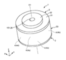
図1は、本発明の第1実施形態に係るロボットを示す斜視図である。なお、図1には、説明の便宜上、互いに直交する3つの軸としてα軸、β軸およびγ軸が図示されており、各軸を示す矢印の先端側を「+」、基端側を「−」とする。また、α軸に平行な方向を「α軸方向」、β軸に平行な方向を「β軸方向」、γ軸に平行な方向を「γ軸方向」という。また、+γ軸方向側を「上」、−γ軸方向側を「下」ともいう。また、γ軸方向から見たものを「平面視」という。また、図1中の基台110側を「基端」、その反対側(エンドエフェクター17側)を「先端」と言う。
<First Embodiment>
≪Robot≫
FIG. 1 is a perspective view showing a robot according to a first embodiment of the present invention. For convenience of explanation, FIG. 1 shows an α axis, a β axis, and a γ axis as three axes orthogonal to each other. The leading end side of the arrow indicating each axis is “+”, and the base end side is “ -". A direction parallel to the α axis is referred to as “α axis direction”, a direction parallel to the β axis is referred to as “β axis direction”, and a direction parallel to the γ axis is referred to as “γ axis direction”. Further, the + γ-axis direction side is also referred to as “upper”, and the −γ-axis direction side is also referred to as “lower”. Also, what is viewed from the γ-axis direction is called “plan view”. Further, the base 110 side in FIG. 1 is referred to as “base end”, and the opposite side (end
図1に示すロボット100は、精密機器やこれを構成する部品等の対象物の給材、除材、搬送および組立等の作業を行うことができる。このロボット100は、単腕ロボットであり、所謂6軸垂直多関節ロボットである。ロボット100は、基台110と、基台110に回動自在に連結されたロボットアーム10と、力検出装置1と、エンドエフェクター17とを有する。
The
基台110は、例えば、床、壁、天井および移動可能な台車上等に固定される部分である。ロボットアーム10は、アーム11(第1アーム)、アーム12(第2アーム)、アーム13(第3アーム)、アーム14(第4アーム)、アーム15(第5アーム)、アーム16(第6アーム)を有する。これらアーム11〜16は、基端側から先端側に向かってこの順に連結されている。各アーム11〜16は、隣り合うアームまたは基台110に対して回動可能になっている。
The
アーム16の先端には、取付部材120(アダプター)によって力検出装置1が接続されている。力検出装置1は、例えば力検出装置1の先端に取り付けられたエンドエフェクター17に加わる力(モーメントを含む)を検出する機能を有する。なお、取付部材120の構成は、力検出装置1をアーム16に対して取り付けることができる構成であればよく、その具体的な構成は限定されない。ただし、取付部材120は、力検出装置1の中心軸A1(軸線)をアーム16の軸O6(アーム16の回動軸)と一致するように力検出装置1を取り付けることができる位置決め部材を備えていることが好ましい。これにより、力検出装置1による外力の検出精度をより高めることができる。
The
エンドエフェクター17は、力検出装置1に対して偏心しており、エンドエフェクター17の作業箇所P、すなわち対象物等に対して直接的に作業を行う箇所が、力検出装置1の中心軸A1に対してずれている。なお、エンドエフェクター17の構成等は、対象物等に対して直接的に作業を行う機能を有すればよく、図示の構成に限定されず、例えば、力検出装置1に対して偏心していなくてもよい。
The
また、図示はしないが、ロボット100は、一方のアームを他方のアーム(または基台110)に対して回動させるモーター等を備える駆動部を有する。また、ロボット100は、図示はしないが、モーターの回転軸の回転角度を検出する角度センサーを有する。
Although not shown, the
以上、ロボット100の構成について簡単に説明した。なお、ロボット100が有するアームの数は、図示では6本であるが、これに限定されず、1〜5本または7本以上であってもよい。
The configuration of the
また、前述したロボット100は、力検出装置1と、力検出装置1が取り付けられたアーム16と、を有する。このようなロボット100によれば、力検出装置1を備えている。そのため、例えば、力検出装置1が検出した外力を、ロボット100を制御する機能を有する制御部(図示せず)にフィードバックすることにより、ロボット100は、より精密に作業を実行することができる。また、力検出装置1が検出した外力によって、ロボット100は、エンドエフェクター17の障害物への接触等を検知することができる。そのため、障害物回避動作および対象物損傷回避動作等を容易に行うことができ、ロボット100は、より安全に作業を実行することができる。
The
以下、力検出装置1について説明する。
[力検出装置]
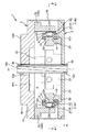
図2は、図1に示す力検出装置を示す斜視図である。図3は、図2に示す力検出装置の縦断面図である。図4は、図2に示す力検出装置の横断面図である。図5は、図3および図4に示す力検出装置が備える力検出素子の断面図である。なお、図3は、図4中のA2−A2線断面図であり、図4は、図3中のA1−A1線断面図である。また、図2および図4には、説明の便宜上、互いに直交する3つの軸としてx軸、y軸およびz軸が図示されており、各軸を示す矢印の先端側を「+」、基端側を「−」とする。また、x軸に平行な方向を「x軸方向」、y軸に平行な方向を「y軸方向」、z軸に平行な方向を「z軸方向」という。また、+z軸方向側を「上」、−z軸方向側を「下」ともいう。また、z軸方向から見たものを「平面視」という。
Hereinafter, the
[Force detection device]
FIG. 2 is a perspective view showing the force detection device shown in FIG. 3 is a longitudinal sectional view of the force detection device shown in FIG. FIG. 4 is a cross-sectional view of the force detection device shown in FIG. FIG. 5 is a cross-sectional view of a force detection element provided in the force detection device shown in FIGS. 3 and 4. 3 is a cross-sectional view taken along line A2-A2 in FIG. 4, and FIG. 4 is a cross-sectional view taken along line A1-A1 in FIG. 2 and 4, for convenience of explanation, the x axis, the y axis, and the z axis are illustrated as three axes orthogonal to each other. The side is “−”. A direction parallel to the x-axis is referred to as an “x-axis direction”, a direction parallel to the y-axis is referred to as a “y-axis direction”, and a direction parallel to the z-axis is referred to as a “z-axis direction”. The + z-axis direction side is also referred to as “upper”, and the −z-axis direction side is also referred to as “lower”. Also, what is viewed from the z-axis direction is called “plan view”.
図2に示す力検出装置1は、力検出装置1に加えられた外力の6軸成分を検出可能な6軸力覚センサーである。ここで、6軸成分は、互いに直交する3つの軸(図示ではx軸、y軸およびz軸)のそれぞれの方向の並進力(せん断力)成分と、当該3つの軸のそれぞれの軸まわりの回転力(モーメント)成分と、からなる。
A
図2〜図4に示すように、力検出装置1は、第1部材3と、第1部材3に対して間隔を隔てて配置されている第2部材2と、第1部材3と第2部材2との間に配置されている複数(本実施形態では4つ)のセンサーデバイス4と、第1部材3および第2部材2の外周部に設けられた側壁部20と、を有する。なお、以下の説明では、4つのセンサーデバイス4のうち、図4中の上側に位置するセンサーデバイス4を「センサーデバイス4a」といい、以降時計回りに順に「センサーデバイス4b」、「センサーデバイス4c」および「センサーデバイス4d」という。また、各センサーデバイス4a、4b、4c、4dを区別しない場合は、それらを「センサーデバイス4」という。また、図4に示すように、力検出装置1は、複数(本実施形態では8つ)の与圧ボルト51と、複数(本実施形態では4つ)のアナログ回路基板6と、を有する。また、力検出装置1は、図示はしないが、デジタル回路基板を有する。また、図2〜図4に示すように、力検出装置1は、その中心軸A1に沿って形成された貫通孔101を有する。
As shown in FIGS. 2 to 4, the
この力検出装置1では、各センサーデバイス4が受けた外力に応じた信号(検出結果)を出力し、それらの信号をアナログ回路基板6およびデジタル回路基板(図示せず)で処理する。これにより、力検出装置1に加えられた外力の6軸成分を検出する。
In this
また、力検出装置1は、アーム16および取付部材120に取付可能に構成されている(図1参照)。力検出装置1の−z軸側の部分(下面201)は、取付部材120を介してアーム16に取り付けられる(図3参照)。一方、力検出装置1の+z軸側の部分(上面301)は、エンドエフェクター17に取り付けられる。したがって、図3に示す力検出装置1は、図1に示す力検出装置1と上下が逆に示されている。
Moreover, the
以下、力検出装置1が備える各部について説明する。
[第1部材]
図3に示すように、第1部材3は、天板31(第1基部)と、天板31の上部側の中央部に設けられた凸部32と、天板31の下部側でかつ外周部に設けられた複数の壁部33(第1与圧部)と、を有する。なお、以下の説明では、4つの壁部33のうち、図4中の上側に位置する壁部33を「壁部33a」といい、以降時計回りに順に「壁部33b」、「壁部33c」および「壁部33d」という。また、各壁部33a、33b、33c、33dを区別しない場合は、それらを「壁部33」という。この第1部材3の平面視での外形は、図2に示すように円形であるが、これに限定されず、例えば、四角形、五角形等の多角形、楕円形等であってもよい。また、第1部材3は、その中央部に中心軸A1に沿って形成された貫通孔35を有する。この貫通孔35は、凸部32をその中央部において貫通している。
Hereinafter, each part with which the
[First member]
As shown in FIG. 3, the
図3に示すように、天板31は、略平板状をなしている。天板31の下方の面(第2部材2側の面)には、凹部311が形成されている。凹部311は、平面視で天板31の中央部に設けられている。凹部311の平面視での外形は、天板31の平面視での外形と相似の円形をなす。このような凹部311を有することで、第1部材3の軽量化を図るとともに力検出装置1の他軸出力(外力が加わっていない軸方向の出力)を小さくすることができる。なお、この凹部311については後で説明する。
As shown in FIG. 3, the
天板31の上部側には、天板31から上方(第2部材2とは反対の方向)に向かって突出した凸部32が設けられている。また、図示では、凸部32は、天板31と一体で形成されている。これにより、部品点数が少なくなり、第1部材3の薄型化を図ることができる。なお、凸部32は、天板31と別部材で形成されていてもよい。
On the top side of the
凸部32は、図1に示すように、平面視で天板31の中央部(中心部)に設けられている。凸部32の平面視での外形は、図示では、天板31の平面視での外形と相似の円形であるが、これに限定されず、例えば、四角形、五角形等の多角形、楕円形等であってもよい。このような凸部32を有することで、力検出装置1の他軸出力(外力が加わっていない軸方向の出力)を小さくすることができる。なお、この凸部32については後で説明する。
As shown in FIG. 1, the
図3に示すように、天板31の下方には、凸部32とは反対側に向かって複数(本実施形態では4つ)の壁部33が立設されている。なお、図示では、各壁部33は、天板31と別部材で形成され、天板31に対し固定されているが、天板31と一体で形成されていてもよい。複数の壁部33は、図4に示すように、力検出装置1の中心軸A1を中心とする同一円周上に沿って互いに等角度(90°)間隔に並んでいる。各壁部33には、後述する与圧ボルト51が挿通される複数の貫通孔37が形成されている。また、図3に示すように、各壁部33の内壁面331(内側の端面)は、天板31に対して垂直な平面である。
As shown in FIG. 3, below the
このような構成の第1部材3が有する凸部32の上面301は、力検出装置1をロボット100のエンドエフェクター17(被取付部材)に取り付ける取付面として機能する。
The
また、第1部材3の構成材料としては、特に限定されないが、例えば、アルミニウム、ステンレス鋼等の金属材料、セラミックス等が挙げられる。
Moreover, although it does not specifically limit as a constituent material of the
[第2部材]
図3に示すように、第2部材2は、底板21(第2基部)と、底板21の上部側に設けられた複数の壁部22(第2与圧部)と、を有する。この第2部材2の平面視での外形は、図2に示すように円形であるが、これに限定されず、例えば、四角形、五角形等の多角形、楕円形等であってもよい。また、図3に示すように、第2部材2は、その中央部に中心軸A1に沿って形成された貫通孔25を有する。
[Second member]
As shown in FIG. 3, the
底板21は、略平板状をなしている。底板21の上部側には、第1部材3側に向かって複数(本実施形態では4つ)の壁部22が立設されている。なお、図示では、各壁部22は、底板21と別部材で形成され、底板21に対し固定されているが、底板21と一体で形成されていてもよい。複数の壁部22は、図4に示すように、力検出装置1の中心軸A1を中心とする同一円周上に沿って互いに等角度(90°)間隔に並んでいる。この壁部22は、前述した第1部材3の壁部33に対して中心軸A1側に配置され、壁部33と対面している。また、壁部22の壁部33側には、壁部33側に向かって突出した部分23を有する。この突出した部分23の頂面231は、前述した壁部33の内壁面331に対し、所定距離(センサーデバイス4を挿入可能な距離)を隔てて対面している。そして、頂面231と内壁面331とは、平行である。また、各壁部33には、後述する与圧ボルト51の先端部が螺合する雌ネジ孔26が複数形成されている。
The
このような第2部材2の下面201は、力検出装置1をアーム16に取り付けるアーム用取付面として機能する。そして、第2部材2(具体的には下面201)は、第2部材2をアーム16に取り付ける取付部材120を接続できるよう構成されている。その具体的な構成等は特に限定されず、例えば、図示しないが、第2部材2の下面201は、ネジ止め、ボルト止め等で取付部材120に装着するために用いる貫通孔(雌ネジ孔)を有する構成、あるいは、フック、L字溝のような係合部を有する構成とすることができる。これにより、取付部材120を介して第2部材2をアーム16の適切な位置に簡単に取り付けることができる。そのため、アーム16に取り付けられた力検出装置1による外力の検出精度をより高めることができる。
Such a
また、第2部材2の構成材料としては、特に限定されないが、前述した第1部材3と同様、例えば、アルミニウム、ステンレス鋼等の金属材料、セラミックス等が挙げられる。なお、第2部材2の構成材料は、第1部材3の構成材料と同じであっても異なっていてもよい。
In addition, the constituent material of the
[側壁部]
図2に示すように、側壁部20は、円筒状をなしており、その上端部および下端部がそれぞれ第1部材3および第2部材2に対して例えばネジ止め、嵌合等によって固定されている。また、図3に示すように、側壁部20と前述した第1部材3の天板31と第2部材2の底板21とで囲まれた空間S、すなわち力検出装置1の内部空間に、複数のセンサーデバイス4が収納されている。
[Sidewall]
As shown in FIG. 2, the
このような側壁部20の構成材料としては、特に限定されないが、前述した第1部材3や第2部材2と同様、例えば、アルミニウム、ステンレス鋼等の金属材料、セラミックス等が挙げられる。なお、側壁部20の構成材料は、第1部材3や第2部材2の構成材料と同じであっても異なっていてもよい。
The constituent material of the
[センサーデバイス]
各センサーデバイス4は、図3に示すように、力検出素子41と、力検出素子41を収納するパッケージ42と、を有している。各センサーデバイス4は、第1部材3の壁部33と第2部材2の壁部22との間に配置されている。力検出素子41は、少なくとも1つの(複数の)圧電素子5を備えている。
[Sensor device]
As shown in FIG. 3, each
(パッケージ)
パッケージ42は、力検出素子41が設置されている凹部をその内側に有する基部421と、その基部421に接合されている蓋体422と、を有し、基部421の凹部が蓋体422により封止されている。これにより、力検出素子41を保護することができる。ここで、基部421は、前述した第2部材2の頂面231に当接している。一方、蓋体422は、前述した第1部材3の内壁面331に当接している。
(package)
The
このようなパッケージ42の基部421の構成材料としては、特に限定されず、例えば、コバール(Fe−Ni−Co合金)等の金属材料、セラミックス等を用いることができる。また、蓋体422の構成材料としては、特に限定されず、例えば、コバール等の金属材料等を用いることができる。なお、基部421の構成材料と蓋体422の構成材料は、同一でもよく、また、異なっていてもよい。また、パッケージ42の平面視での形状は、本実施形態では四角形をなしているが、これに限定されず、例えば、五角形等の他の多角形、円形、楕円形等であってもよい。
The constituent material of the
(力検出素子)
図5に示す力検出素子41は、力検出素子41に加えられた外力のX軸方向の成分に応じた電荷QX、力検出素子41に加えられた外力のY軸方向の成分に応じた電荷QY、および、力検出素子41に加えられた外力のZ軸方向の成分に応じた電荷QZを出力する機能を有する。この力検出素子41は、X軸に平行な外力(せん断力)に応じて電荷QXを出力する圧電素子5aと、Z軸に平行な外力(圧縮/引張力)に応じて電荷QZを出力する圧電素子5bと、Y軸に平行な外力(せん断力)に応じて電荷QYを出力する圧電素子5cと、基準電位、例えばグランド電位(GND)に電気的に接続されているグランド電極層54、55、56、57と、を有する。また、力検出素子41は、圧電素子5a、5b、5cおよびグランド電極層54、55、56、57を備える構造体50を支持する支持基板58、59(ダミー基材)を有する。ここで、支持基板58、グランド電極層54、圧電素子5a、グランド電極層55、圧電素子5b、グランド電極層56、圧電素子5c、グランド電極層57、支持基板59の順でこれらが積層されている。なお、以下では、圧電素子5a、5b、5cをそれぞれ「圧電素子5」ともいう。
(Force detection element)
The
圧電素子5aは、圧電体層51a、出力電極層52a、圧電体層53aがこの順で積層されて構成されている。同様に、圧電素子5bは、圧電体層51b、53bと、これらの間に配置されている出力電極層52bと、を有する。また、圧電素子5cは、圧電体層51c、53cと、これらの間に配置されている出力電極層52cと、を有する。
The piezoelectric element 5a is configured by stacking a piezoelectric layer 51a, an
圧電素子5は、水晶を含む。すなわち、圧電素子5は、水晶で構成された圧電体層51a、53a、51b、53b、51c、53cを備えている。これにより、高感度、広いダイナミックレンジ、高い剛性等の優れた特性を有する力検出装置1を実現することができる。
The
図5に示すように、圧電体層51a、53a、51b、53b、51c、53cは、それらを構成する水晶の結晶軸であるX軸の方向が異なっている。すなわち、圧電体層51aを構成する水晶のX軸は、図5中紙面奥側を向いている。圧電体層53aを構成する水晶のX軸は、図5中紙面手前側を向いている。圧電体層51bを構成する水晶のX軸は、図5中左側を向いている。圧電体層53bを構成する水晶のX軸は、図5中右側を向いている。圧電体層51cを構成する水晶のX軸は、図5中上側を向いている。圧電体層53cを構成する水晶のX軸は、図5中下側を向いている。このような圧電体層51a、53a、51c、53cは、それぞれYカット水晶板で構成され、X軸の向きが互いに90°ずつ異なっている。また、圧電体層51b、53bは、それぞれXカット水晶板で構成され、X軸の向きが互いに180°異なっている。
As shown in FIG. 5, the
なお、本実施形態では、圧電体層51a、53a、51b、53b、51c、53cは、それぞれ、水晶で構成されているが、これらは、水晶以外の圧電材料を用いた構成であってもよい。水晶以外の圧電材料としては、例えば、トパーズ、チタン酸バリウム、チタン酸鉛、チタン酸ジルコン酸鉛(PZT:Pb(Zr,Ti)O3)、ニオブ酸リチウム、タンタル酸リチウム等が挙げられる。
In the present embodiment, the
また、出力電極層52a、52b、52cおよびグランド電極層54、55、56、57を構成する材料は、それぞれ、電極として機能し得る材料であれば特に限定されないが、例えば、ニッケル、金、チタニウム、アルミニウム、銅、鉄、クロムまたはこれらを含む合金が挙げられ、これらのうちの1種または2種以上を組み合わせて(例えば積層して)用いることができる。これら出力電極層52a、52b、52cおよびグランド電極層54、55、56、57は、図示しない配線および端子等(例えば銀ペースト等で構成された配線等)を介して、アナログ回路基板6に電気的に接続されている。
The materials constituting the
また、本実施形態では、支持基板58、59は、それぞれ、水晶で構成されている。支持基板58は、隣り合う圧電体層51aと同様の構成の水晶板(Yカット水晶板)で構成されており、X軸の向きも圧電体層51aと同様である。支持基板59は、隣り合う圧電体層53cと同様の構成の水晶板(Yカット水晶板)で構成されており、X軸の向きも圧電体層53cと同様である。水晶は異方性を有するため、X軸、Y軸およびZ軸方向で熱膨張係数が異なる。そのため、熱膨張による応力を抑えるために支持基板58、59は隣り合う圧電体層と同様の構成および配置(向き)であることが好ましい。
In the present embodiment, the
また、支持基板58、59の厚さは、それぞれ、各圧電体層51a、53a、51b、53b、51c、53cの厚さよりも厚い。
The support substrates 58 and 59 are thicker than the
このような支持基板58、59を備えることで、力検出素子41をパッケージ42に安定的に接合(接続)することができる。また、パッケージ42が金属材料等の導電性を有する部材で構成されている場合であっても、パッケージ42や前述した図示しない配線および端子等との短絡を回避することができる。
By providing
なお、支持基板58、59は、それぞれ、水晶以外の導電性を有さない材料を用いた構成であってもよい。
Each of the
以上、力検出素子41について説明した。前述したように、力検出素子41は、複数の圧電素子5を備える。これにより、力検出装置1の高感度化を図ったり、検出軸の多軸化を図ったりすることができる。
The
なお、力検出素子41を構成する圧電素子および圧電体層の数は、前述した数に限定されない。例えば、1つの圧電素子が備える圧電体層の数が1つまたは3つ以上であってもよいし、圧電素子の数が2つまたは4つ以上であってもよい。
Note that the number of piezoelectric elements and piezoelectric layers constituting the
また、力検出素子41の平面視形状は、図示では、四角形であるが、これに限定されず、例えば、五角形等の他の多角形、円形、楕円形等であってもよい。
In addition, the plan view shape of the
以上説明したような各センサーデバイス4は、力検出素子41が有する圧電素子5a、5b、5cの積層方向D1が中心軸A1に直交するよう(yz平面の面方向に)に配置されている(図3および図5参照)。また、図4に示すように、4つのセンサーデバイス4は、中心軸A1に沿った方向から見たとき、中心軸A1を通りy軸に平行な線分CLに対して対称となるように配置されている。また、各センサーデバイス4は、中心軸A1に直交する方向から見たとき(図3の側面視で)、第1部材3の天板31と第2部材2の底板21との間の中間部に位置している。また、本実施形態では、例えば、グランド電極層57が壁部22側に位置し、グランド電極層54が壁部33側に位置している。
Each
また、本実施形態では、各センサーデバイス4(各力検出素子41)と中心軸A1との離間距離は、等しい。また、各センサーデバイス4(各力検出素子41)と上面301の幾何学的な中心との離間距離は、等しい。また、各センサーデバイス4(各力検出素子41)と下面201の幾何学的な中心との離間距離は、等しい。なお、上述の離間距離が等しいことは、機械的な設計および設置等の誤差を含む。
Moreover, in this embodiment, the separation distance of each sensor device 4 (each force detection element 41) and central axis A1 is equal. Further, the separation distance between each sensor device 4 (each force detection element 41) and the geometric center of the
[与圧ボルト(固定部材)]
複数の与圧ボルト51は、第1部材3の壁部33と第2部材2の壁部22とでセンサーデバイス4(より具体的には複数の圧電素子5)を挟んで与圧した状態で壁部33および壁部22を互いに固定している(図3および図4参照)。各与圧ボルト51は、壁部33側から壁部33の貫通孔37に挿通され、与圧ボルト51の先端部に形成された雄ネジを壁部22に形成された雌ネジに螺合されている。このような複数の与圧ボルト51により、第1部材3の内壁面331と第2部材2の頂面231とでセンサーデバイス4のパッケージ42を介して力検出素子41を挟んで与圧することができる。また、各与圧ボルト51の締結力を適宜調整することで、力検出素子41に対して、所定の大きさの圧電素子5の積層方向D1の圧力を与圧として加えることができる(図5参照)。
[Pressure bolt (fixing member)]
The plurality of pressurizing
このような各与圧ボルト51の構成材料としては、特に限定されないが、例えば、各種金属材料等が挙げられる。なお、各与圧ボルト51の位置および数は、それぞれ、図示の位置および数に限定されない。また、与圧ボルト51の数は、例えば、1つのセンサーデバイス4に対して1つまたは3つ以上であってもよい。また、圧電素子5を備える力検出素子41は、第1部材3と第2部材2との間(特に壁部33と壁部22との間)に挟持されているが、これに限定されず、第1部材3と第2部材2との間に任意の構成で支持されていればよい。
The constituent material of each pressurizing
[アナログ回路基板]
図3に示すように、アナログ回路基板6は、空間S、すなわち第1部材3と第2部材2との間に配置されている。このアナログ回路基板6には、第2部材2の突出した部分23が挿通されている貫通孔61と、各与圧ボルト51が挿通されている貫通孔62と、が形成されている(図3および図4参照)。アナログ回路基板6は、部分23に挿通された状態で、センサーデバイス4に対して中心軸A1側に配置されている。これにより、センサーデバイス4の近傍にアナログ回路基板6を設けることができ、センサーデバイス4からの配線長さを短くすることができる。そのため、構造の簡素化に寄与することができる。
[Analog circuit board]
As shown in FIG. 3, the
また、アナログ回路基板6は、前述したセンサーデバイス4に電気的に接続されている。アナログ回路基板6は、図示はしないが、センサーデバイス4の力検出素子41から出力された電荷Q(QX、QY、QZ)をそれぞれ電圧V(VX、VY、VZ)に変換するチャージアンプ(変換出力回路)を備えている。このチャージアンプは、例えば、オペアンプと、コンデンサーと、スイッチング素子と、を有して構成することができる。
The
[デジタル回路基板]
デジタル回路基板は、図示しないが、例えば、第2部材2上に設けることができる。このデジタル回路基板は、前述したアナログ回路基板6に電気的に接続されている。デジタル回路基板は、図示しないが、アナログ回路基板6からの電圧VX、VY、VZに基づいて、外力を検出(演算)する外力検出回路を備えている。外力検出回路は、x軸方向の並進力成分Fx、y軸方向の並進力成分Fy、z軸方向の並進力成分Fz、X軸周りの回転力成分Mx、Y軸周りの回転力成分My、Z軸周りの回転力成分Mzを演算する。この外力検出回路は、例えば、ADコンバーターと、このADコンバーターに接続されたCPU等の演算回路と、を有して構成することができる。
[Digital circuit board]
Although not shown, the digital circuit board can be provided on the
ここで、本実施形態では、各センサーデバイス4は、圧電素子5の積層方向D1が中心軸A1に直交するように配置されており、4つのセンサーデバイス4は、線分CLに対して対称となるように配置されている(図4および図5参照)。そして、前述したように、壁部33と壁部22とによって圧電素子5の積層方向D1に対して平行な方向に与圧が加えられている。そのため、デジタル回路基板では、温度変動の影響を受けやすい電荷QZを用いずに、並進力成分Fx、Fy、Fzおよび回転力成分Mx、My、Mzの演算が可能である。そのため、力検出装置1は、温度の変動による影響を受けにくく、高精度な検出が可能である。これにより、例えば高温環境下に力検出装置1が置かれて第1部材3および第2部材2が熱膨張し、その熱膨張によって圧電素子5に対する与圧が所定の値から変化してノイズ成分となることを低減または零にすることができる。
Here, in this embodiment, each
以上、力検出装置1の基本的な構成について説明した。このような力検出装置1では、前述したように、第1部材3は、圧電素子5(力検出素子41)を与圧する「第1与圧部」としての壁部33を有し、第2部材2は、圧電素子5(力検出素子41)を与圧する「第2与圧部」としての壁部22を有する。そして、本実施形態では、与圧ボルト51によって、第1部材3と第2部材2とが固定されている。これにより、圧電素子5に対して一定の圧力を予め与えておくことができ、力検出装置1による外力の検出精度をより高めることができる。
The basic configuration of the
また、前述したように、第1部材3は、中心軸A1に沿って形成された貫通孔35を有する。また、第2部材2は、中心軸A1に沿って形成された貫通孔25を有する。そして、貫通孔35と貫通孔25と、これらを空間Sで連通している円柱状の空間(長さが力検出装置1のz軸方向の厚さに等しい円柱状の空間)とで、貫通孔101が構成されている。すなわち、力検出装置1は、第1部材3と第2部材2とに開口した貫通孔101を有する。また、本実施形態では、貫通孔101は、中心軸A1に沿って形成されている。これにより、貫通孔101に例えば配線や配管等を有する可撓性部材(ケーブル等)を挿通させることができる。そのため、例えば、エンドエフェクター17(被取付部材)の配線103をロボット100の基台110から力検出装置1の貫通孔101を介してエンドエフェクター17に効率よく引きまわすことができる(図1および図3参照)。
Further, as described above, the
また、図3に示すように、貫通孔101の内部には、円筒状のチューブ102(緩衝部材)が設けられている。このチューブ102は、例えば、取付部材120またはエンドエフェクター17に接続されている(図1および図3参照)。本実施形態では、チューブ102の外周面は、貫通孔25、35を形成している壁面と離間している。なお、チューブ102は、貫通孔101内に位置していれば、当該壁面と離間していなくてもよい。このようなチューブ102は、配線103が貫通孔101の内壁に接触することを防ぐように配線103の位置を規制する位置規制部材としての機能を有する。そのため、配線103の内壁への接触による力検出装置1の誤検出を低減または防止することができる。
As shown in FIG. 3, a cylindrical tube 102 (buffer member) is provided inside the through
また、ロボットアーム10の内部および力検出装置1のチューブ102内に配線103配置することができるため、ロボットアーム10の外部や力検出装置1の外部に配線103を配置しなくて済む。そのため、ロボットアーム10の動きに伴って力検出装置1の外部に配置された配線103が力検出装置1に衝突することによって力検出装置1に不要な外力が加わることを低減することができる。
Further, since the
なお、チューブ102の形状は、円柱状に限定されない。チューブ102の形状は、位置規制部材として機能すれば如何なる形状であってもよい。
Note that the shape of the
次に、上述した第1部材3の凸部32を有することで、力検出装置1の他軸出力を小さくすることができることについて、従来の力検出装置1aにおける問題点とともに説明する。
Next, the fact that the other-axis output of the
図6は、従来の構成の力検出装置がエンドエフェクターに取り付けられている状態を模式的に示す側面図である。図7は、図6に示す力検出装置における外力が加わったときの期待値と実際の出力値との関係を示す図である。図8は、図6に示す力検出装置における距離Taと比率Fx/Fzとの関係を示す図である。 FIG. 6 is a side view schematically showing a state in which a force detection device having a conventional configuration is attached to an end effector. FIG. 7 is a diagram showing a relationship between an expected value and an actual output value when an external force is applied in the force detection device shown in FIG. FIG. 8 is a diagram showing the relationship between the distance Ta and the ratio Fx / Fz in the force detection device shown in FIG.
図6に示す力検出装置1aの上面(図6中の上側の面)は平坦であり、力検出装置1aの上面の全域はエンドエフェクター17に接触して固定されている。例えば、対象物がエンドエフェクター17の作業箇所Pに接触して作業箇所Pに矢印C1方向の外力Fが加わった場合、力検出装置1によって並進力成分Fzとともに回転力成分Myが検出されると想定される(図7中の期待値の列を参照)。例えば、大きさMの並進力成分Fzとともに、大きさMと距離Taとに応じた大きさTMの並進力成分Fyを検出すると想定される。距離Taは、中心軸A1aと作業箇所Pとの間の距離である。しかし、力検出装置1aでは、実際には、並進力成分Fzおよび回転力成分Myとともに、並進力成分Fxも検出される(図7中の出力値の列を参照)。これは、力検出装置1aに加わる力のy軸周りの回転中心が力検出素子41が備えるセンサーデバイスの中心からずれてしまい、力検出装置1aが備えるセンサーデバイスに本来加わっていない力が過剰に加わるためであると考えられる。また、外力Fが加わる作業箇所Pが中心軸A1aに対して離間するほど、図8に示すように、並進力成分Fxの大きさが増えていく傾向がある。
The upper surface (upper surface in FIG. 6) of the
このように、中心軸A1aに対してずれた位置にある作業箇所Pに外力Fが加わると、従来の力検出装置1aでは、他軸出力(図6の例では並進力成分Fx)が大きくなってしまう。そのため、このような力検出装置1aに対して偏心しているエンドエフェクター17等を使って作業する場合、力検出装置1aには、本来加わっていない力が見かけ上加わってしまう。また、この多軸出力を例えばデジタル回路基板等で補正をしたとしても、多軸出力が大き過ぎて十分に補正しきれない。そのため、偏心しているエンドエフェクター17を用いた場合、従来の力検出装置1aの検出結果を基にして、偏心していないエンドエフェクターを用いて作業する場合と同様の作業をすることが難しい。
As described above, when the external force F is applied to the work location P that is shifted from the center axis A1a, the other-axis output (the translational force component Fx in the example of FIG. 6) increases in the conventional
そこで、本実施形態の力検出装置1は、他軸出力を小さくするべく、前述したように、凸部32を有する第1部材3を備えている(図2参照)。以下、この凸部32を設けることにより他軸出力を小さくできることを、主に図9〜図11を参照しつつ説明する。
Therefore, the
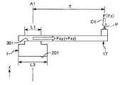
図9は、図2に示す力検出装置がエンドエフェクターに取り付けられている状態を模式的に示す側面図である。図10は、図2に示す力検出装置が有する第1部材の縦断面図である。図11は、図9に示す力検出装置における凸部の幅の影響を示す図である。 FIG. 9 is a side view schematically showing a state in which the force detection device shown in FIG. 2 is attached to the end effector. FIG. 10 is a longitudinal sectional view of a first member included in the force detection device shown in FIG. FIG. 11 is a diagram illustrating the influence of the width of the convex portion in the force detection device illustrated in FIG. 9.
図11は、図10に示す第1部材3の幅L3(径)を一定にしたまま凸部32の幅L1(径)を変更したときの並進力成分Fxyの大きさを示している。図11中の縦軸は、図9に示すようにエンドエフェクター17の作業箇所Pに矢印C1方向の外力Fが加わったときに力検出装置1から出力される並進力成分Fxyの並進力成分Fzに対する比率Fxy/Fzを示している。比率Fxy/Fzが0%に近い程、並進力成分Fxyが小さい。また、図11に示すグラフの横軸は、幅L1の幅L3に対する比率L1/L3を示している。
FIG. 11 shows the magnitude of the translational force component Fxy when the width L1 (diameter) of the
なお、図9に示す力検出装置1は、図4の下側に位置するセンサーデバイス4が図9中の紙面手前側に位置するようにエンドエフェクター17に取り付けられている。すなわち、エンドエフェクター17は、力検出装置1の図4中右側に突出している。また、作業箇所Pと中心軸A1とを結ぶ軸線に沿った方向の並進力成分をFxy(並進力成分Fx、Fyを有する成分)とする(図9参照)。また、中心軸A1上の点を零点とし、この零点よりも図9中右側に向かう並進力成分Fxyを+(プラス)とし、零点よりも図9中左側に向かう並進力成分Fxyを−(マイナス)とする。
9 is attached to the
図11に示すように、比率L1/L3に応じて比率Fxy/Fzは線形的に変化している。すなわち、幅L1を変更すると、幅L1に応じて並進力成分Fxyの大きさが変化している。そして、比率L1/L3が100%である場合、すなわち凸部32を有さない場合に、最も並進力成分Fxyが大きくなっており、凸部32を有することで、凸部32を有さない場合に比べて比率Fxy/Fzが小さくすることができる。すなわち、凸部32を設けることで並進力成分Fxyを小さくすることができる。
As shown in FIG. 11, the ratio Fxy / Fz changes linearly according to the ratio L1 / L3. That is, when the width L1 is changed, the magnitude of the translational force component Fxy changes according to the width L1. When the ratio L1 / L3 is 100%, that is, when the
また、比率Fxy/Fzが60%程度になるまでは、幅L1が小さくなるほど並進力成分Fxy(+Fxy)を小さくすることができる。一方、比率Fxy/Fzが60%程度を超えると、幅L1が小さくなるほど並進力成分Fxy(−Fxy)が大きくなっている。このような傾向は、図9中の矢印C1方向の外力Fが加わったときに力検出装置1(特に第1部材3の壁部33a、33c)が受ける変形(変位)に起因していると考えられる。この点について、主に図9、図12〜図17を参照しつつ以下に説明する。
Further, the translational force component Fxy (+ Fxy) can be reduced as the width L1 decreases until the ratio Fxy / Fz reaches approximately 60%. On the other hand, when the ratio Fxy / Fz exceeds about 60%, the translational force component Fxy (−Fxy) increases as the width L1 decreases. Such a tendency is caused by deformation (displacement) that the force detection device 1 (particularly, the
図12は、図11に示すL1/L3が25%であるときの力検出装置の変形状態を模式的に示す図である。図13は、図11に示すL1/L3が63%であるときの力検出装置の変形状態を模式的に示す図である。図14は、図11に示すL1/L3が100%であるときの力検出装置の変形状態を模式的に示す図である。図15は、図11に示すL1/L3が25%であるときのセンサーユニットにかかる力の回転中心を説明するための図である。図16は、図11に示すL1/L3が63%であるときのセンサーユニットにかかる力の回転中心を説明するための図である。図17は、図11に示すL1/L3が100%であるときのセンサーユニットにかかる力の回転中心を説明するための図である。なお、図12および図13では、凸部32の図示を省略している。
FIG. 12 is a diagram schematically showing a deformed state of the force detection device when L1 / L3 shown in FIG. 11 is 25%. FIG. 13 is a diagram schematically showing a deformed state of the force detection device when L1 / L3 shown in FIG. 11 is 63%. FIG. 14 is a diagram schematically showing a deformed state of the force detection device when L1 / L3 shown in FIG. 11 is 100%. FIG. 15 is a diagram for explaining the rotation center of the force applied to the sensor unit when L1 / L3 shown in FIG. 11 is 25%. FIG. 16 is a diagram for explaining the rotation center of the force applied to the sensor unit when L1 / L3 shown in FIG. 11 is 63%. FIG. 17 is a diagram for explaining the rotation center of the force applied to the sensor unit when L1 / L3 shown in FIG. 11 is 100%. In FIGS. 12 and 13, the
図12〜図14に示すように、比率L1/L3の大きさによって第1部材3(力検出装置1)の変形の仕方が異なっている。各第1部材3は、外力Fが加わると軸O1を中心軸として変形(変位)する(図9、図12〜図14参照)。軸O1は、作業箇所Pと中心軸A1とを結ぶ軸線(またはエンドエフェクター17の延出方向に沿った軸)および中心軸A1(または外力Fの方向に沿った軸)の双方に直交する軸である。
As shown in FIGS. 12-14, the deformation | transformation method of the 1st member 3 (force detection apparatus 1) changes with the magnitude | sizes of ratio L1 / L3. When the external force F is applied, each
この軸O1の位置は、図12〜図14に示すように、比率L1/L3の大きさによって異なっている。そして、軸O1の位置は比率L1/L3が小さくなるほど、すなわちエンドエフェクター17と力検出装置1との接触面積が小さくなるほど、力検出装置1内の上側に位置している。
The position of the axis O1 varies depending on the ratio L1 / L3 as shown in FIGS. The position of the axis O1 is located on the upper side in the
具体的には、図17に示すように、比率L1/L3が100%である場合には、軸O1は、センサーデバイス4a、4cの外部(図17中の右下)に位置している。この状態から幅L1を小さくしていくと、軸O1は、センサーデバイス4a、4cに近づいていく。そして、図16に示すように、例えば、比率L1/L3が68%である場合、軸O1は、センサーデバイス4a、4cの内部に位置する。この状態からさらに幅L1を小さくしていくと、軸O1はセンサーデバイス4a、4c内を図16中の左上側に向かって横断していく。そして、図15に示すように、例えば、比率L1/L3が25%である場合、軸O1の位置は、センサーデバイス4a、4cの外部(図15中の左上)に位置する。なお、比率L1/L3が25%である場合には、比率L1/L3が100%である場合よりもセンサーデバイス4a、4cの近傍に軸O1が位置している。このように、比率L1/L3の大きさによって軸O1の位置が変わる。
Specifically, as shown in FIG. 17, when the ratio L1 / L3 is 100%, the axis O1 is located outside the
なお、比率L1/L3が100%である場合、外力Fが加わると第1部材3の上部のうち作業箇所Pに最も近い部分に最も力が加わる(図6および図14参照)。これにより、エンドエフェクター17の変形に伴って、第1部材3の上部の作業箇所Pに近い部分が下方に押され、第1部材3の上部の作業箇所Pから遠い部分が持ち上がるように第1部材3は時計周りに変形する。一方、比率L1/L3が68%、25%である場合には、外力Fが加わると、凸部32の上面301のうち作業箇所Pに最も近い部分に最も力が加わる(図9、図12および図13参照)。これにより、エンドエフェクター17の変形に伴って、凸部32の上面301の作業箇所Pに最も近い部分が下方に押され、凸部32の上面301の作業箇所Pから最も遠い部分が持ち上がるように第1部材3は時計周りに変形する。また、比率L1/L3が25%である場合には、反時計周りにも変形すると考えられる。これは、比率L1/L3が25%である場合には、幅L1が小さくなることで取付面として機能する上面301の面積が小さくなり、力検出装置1のエンドエフェクター17に対する取り付けの安定性が低下することが影響していると考えられる。
When the ratio L1 / L3 is 100%, when the external force F is applied, the force is applied most to the portion of the upper portion of the
このように、凸部32を設けて幅L1(上面301の面積)を調節することにより、センサーデバイス4a、4cの内部に軸O1を位置させることができる。これにより、壁部33a、33cの作業箇所Pと中心軸A1とを結ぶ軸線方向に沿った変形量を小さくすることができ、これに伴ってセンサーデバイス4a、4cの作業箇所Pと中心軸A1とを結ぶ軸線方向に沿った変形量を小さくすることができる(図12〜図17参照)。そのため、前述した外力Fによって力検出装置1から出力される並進力成分Fxyを小さくすることができる。
Thus, by providing the
本実施形態では、前述したように、各センサーデバイス4が線分CLに対して対称となるように配置されていて、圧電素子5の積層方向D1が中心軸A1に直交しており、電荷QZを用いずに並進力成分Fx、Fy、Fzおよび回転力成分Mx、My、Mzの演算を行う(図4および図5参照)。そのため、第1部材3の作業箇所Pと中心軸A1とを結ぶ軸線方向に沿った変形(変位)は、センサーデバイス4a、4cから出力される電荷QX、QYの出力値に特に影響を与える。それゆえ、前述したように、センサーデバイス4a、4cの作業箇所Pと中心軸A1とを結ぶ軸線方向に沿った変形量を小さくすることで、外力Fを受けたときの力検出装置1から出力される並進力成分Fxyを抑制することができる。
In the present embodiment, as described above, the
なお、凸部32の厚さ(高さ)や、作業箇所Pと中心軸A1とを結ぶ軸線の長さ(離間距離T)、外力Fの大きさ等を変化させても、図11に示す傾向と同様の傾向を示した。軸O1を、各センサーデバイス4を含むx−y平面内に位置させることで、多軸出力(本実施形態では並進力成分Fxy)を小さくすることができる。
It should be noted that even if the thickness (height) of the
また、比率L1/L3は、35%以上75%以下であることが好ましい(図11参照)。これにより、比率Fxy/Fzを±200%程度にすることができる。すなわち、凸部32を有さない場合に比べて並進力成分Fxyを半減することができる。さらに、比率L1/L3は、50%以上70%以下であることがより好ましく、55%以上65%以下であることがさらに好ましい。これにより、力検出装置1をより安定してエンドエフェクター17に取り付けることができるとともに、並進力成分Fxyをさらに低減することができる。
Moreover, it is preferable that ratio L1 / L3 is 35% or more and 75% or less (refer FIG. 11). Thereby, the ratio Fxy / Fz can be about ± 200%. That is, the translational force component Fxy can be halved compared to the case where the
ここで、本実施形態では、比率L1/L3が75%以下であると、凸部32は、平面視で複数のセンサーデバイス4よりも内側に位置している状態となる。言い換えると、凸部32の幅L1は、2つの向かい合うセンサーデバイス4(例えばセンサーデバイス4bとセンサーデバイス4d)の離間距離よりも短い。このように凸部32を位置させることで、凸部32を有さない場合に比べて並進力成分Fxyを半減することができる。
Here, in this embodiment, the
以上説明したように、力検出装置1は、アーム16を有するロボット100に取り付け可能な力検出装置1である(図1参照)。力検出装置1は、「被取付部材」としてのエンドエフェクター17を取り付け可能な「取付面」としての上面301を有する凸部32を備える第1部材3と、アーム16に取り付けられる第2部材2と、第1部材3と第2部材2との間に支持され(挟持され)、第1部材3と第2部材2とに加えられる外力(外力F)を検出する少なくとも1つの(好ましくは複数の)圧電素子5(力検出素子41)と、を備える(図3〜図5参照)。また、本実施形態では、凸部32は、第2部材2とは反対側に突出している。このような力検出装置1によれば、中心軸A1に対してずれた位置に外力Fが加わった場合でも、他軸出力(図10では並進力成分Fxy)を小さくすることができ、力検出装置1による外力Fの検出精度を高めることができる。したがって、力検出装置1によれば、力検出装置1の中心軸A1に対してずれた位置に外力が加わった場合と、力検出装置1の中心軸A1上の位置に外力Fが加わった場合との双方において、力検出装置1による外力Fの検出精度を高めることができる。
As described above, the
また、前述したように、力検出装置1は、第1部材3と第2部材2とによって挟持され、少なくとも1つの圧電素子5(本実施形態では複数の圧電素子5)を備えるセンサーデバイス4を複数有する。そして、平面視で、すなわち「取付面」としての上面301の法線方向から見て、凸部32は、複数のセンサーデバイス4よりも内側に位置している。これにより、力検出装置1の中心軸A1に対してずれた位置に外力Fが加わった場合でも、他軸出力をより小さくすることができ、力検出装置1による外力Fの検出精度をより高めることができる。特に、前述したように、凸部32を有さない場合に比べて他軸出力(図10では並進力成分Fxy)を半減することができる。
As described above, the
また、前述したように、本実施形態では、力検出装置1は、エンドエフェクター17に取り付けられている。言い換えると、力検出装置1の取付面としての上面301が取り付けられる「被取付部材」は、エンドエフェクター17である。これにより、力検出装置1によってエンドエフェクター17が受けた外力Fを高精度に検出することができる。そのため、ロボット100は、例えばエンドエフェクター17による対象物に対する作業をより高精度に行うことができる。
Further, as described above, in the present embodiment, the
特に、前述したように、エンドエフェクター17は、その作業箇所Pが中心軸A1に対してずれており、力検出装置1(およびアーム16)に対して偏心している。すなわち、エンドエフェクター17の作業箇所Pは、「取付面」としての上面301の中心(幾何学的な中心)を通る上面301の法線に対してずれている。このようなエンドエフェクター17に対して力検出装置1を用いることは特に有効であり、このようなエンドエフェクター17であっても、力検出装置1によれば、他軸出力を小さくすることができ、外力Fの検出精度を高めることができる。また、例えば、エンドエフェクター17は、その先端部に、ネジ止めを行うドライバーを備えた構成とすることができる。ドライバーを備えたエンドエフェクター17(偏心エンドエフェクター)である場合に、力検出装置1を用いることは特に有効である。力検出装置1を用いることでドライバーによるネジ止めを高精度に行うことができる。
In particular, as described above, the work position P of the
次に、第1部材3が凹部311を有することで第1部材3の軽量化を図るとともに力検出装置1の他軸出力を小さくすることができることを、主に図18、図19を参照しつつ説明する。
Next, referring to FIGS. 18 and 19, the
図18は、図10に示す第1部材の凹部の幅の影響を示す図である。図19は、図10に示す第1部材の凹部の高さの影響を示す図である。 18 is a diagram illustrating the influence of the width of the concave portion of the first member shown in FIG. FIG. 19 is a diagram showing the influence of the height of the concave portion of the first member shown in FIG.
図18は、図10に示す第1部材3の幅L3を一定にしたまま凹部311の幅L2(径)を変更したときの並進力成分Fxyの大きさを示している。図18は、例えば、幅L3が80mm、幅L1が55mm、第1部材3の高さが6mm、天板31の高さt3が5mm、凸部32の高さt1が1mm、比率L1/L3が68.75%である場合の第1部材3を用いている。
FIG. 18 shows the magnitude of the translational force component Fxy when the width L2 (diameter) of the
図18に示すように、第1部材3の幅L3に対して凹部311の幅L2を変更すると、並進力成分Fxyの大きさが変わる。このように、前述した幅L2の大きさを調整することに加えて、幅L3の大きさを調整して並進力成分Fxyを小さくすることも可能である。これにより、幅L2の大きさをある程度確保することができる。そのため、取付面としての上面301の面積を大きくして力検出装置1のエンドエフェクター17に対する取り付けの安定性を十分に確保しつつ、凹部311の幅L3を大きくして第1部材3の軽量化を図ることができる。したがって、例えば、図11に示す比率L1/L3を60%以上80%以下とし、比率L2/L3を53%以上70%以下とすることも好適である。これにより、第1部材3の軽量化を図ることができるとともに、並進力成分Fxyをより小さくすることができるという効果をより顕著に発揮することができる。
As shown in FIG. 18, when the width L2 of the
このように、第1部材3は、凸部32とは反対側に凹部311を有する。これにより、第1部材3の軽量化を図ることができるとともに、他軸出力をより小さくすることができ、外力Fの検出精度をより高めることができる。
As described above, the
また、図19は、図10に示す第1部材3の幅L3を一定にしたまま凹部311の高さt2(厚さ)を変更したときの並進力成分Fxyの大きさを示している。図19に示すように、天板31の高さ以下の範囲内で高さt2(厚さ)を変更しても、並進力成分Fxyの大幅な変化はない。そのため、天板31の高さ以下の範囲内で高さt2(厚さ)を大きくすることで、並進力成分Fxyを低下させるという効果を発揮しつつ、第1部材3の更なる軽量化を図ることができる。
FIG. 19 shows the magnitude of the translational force component Fxy when the height t2 (thickness) of the
<第2実施形態>
図20は、本発明の第2実施形態に係るロボットが備える力検出装置を示す縦断面図である。なお、以下の説明では、第2実施形態に関し、前述した実施形態との相違点を中心に説明し、同様の事項に関してはその説明を省略する。また、図20において、前述した実施形態と同様の構成は、同一符号を付している。
Second Embodiment
FIG. 20 is a longitudinal sectional view showing a force detection device provided in the robot according to the second embodiment of the present invention. In the following description, the second embodiment will be described with a focus on differences from the above-described embodiment, and description of similar matters will be omitted. In FIG. 20, the same components as those in the above-described embodiment are denoted by the same reference numerals.
図20に示す力検出装置1Aが備える第1部材3Aは、天板31(第1基部)と、凸部32を備える部材34と、複数の壁部33(第1与圧部)と、を有する。部材34の凸部32を除く部分は、略平板状をなしており、天板31に対して着脱可能に設けられている。これにより、所望の形状や大きさの凸部32を有する部材34に変更することが容易となり、例えばエンドエフェクター17の種類等に応じた部材34に簡単に変更することができる。
A
なお、部材34は、着脱できず天板31に固定されていてもよい。また、図示では、部材34の凸部32を除く部分の平面視での外形は、天板31と同じ形状であるが、天板31と異なる形状であってもよい。
Note that the
このような力検出装置1Aによっても、外力(外力F)の検出精度を高めることができる。 Also with such a force detection device 1A, the detection accuracy of the external force (external force F) can be increased.
<第3実施形態>
図21は、本発明の第3実施形態に係るロボットを示す斜視図である。なお、以下の説明では、第2実施形態に関し、前述した実施形態との相違点を中心に説明し、同様の事項に関してはその説明を省略する。また、図20において、前述した実施形態と同様の構成は、同一符号を付している。
<Third Embodiment>
FIG. 21 is a perspective view showing a robot according to the third embodiment of the present invention. In the following description, the second embodiment will be described with a focus on differences from the above-described embodiment, and description of similar matters will be omitted. In FIG. 20, the same components as those in the above-described embodiment are denoted by the same reference numerals.
図21に示すロボット600は、複腕ロボットであり、基台610と、第1のロボットアーム620と、第2のロボットアーム630と、第1のロボットアーム620の先端側に設けられた第1のエンドエフェクター640aと、第2のロボットアーム630の先端側に設けられた第2のエンドエフェクター640bと、2つの力検出装置1とを有する。
A
第1のロボットアーム620は、アーム621(第1アーム)とアーム622(第2アーム)とを有し、アーム621、622が回動自在に連結することにより構成されている。アーム622の先端には、取付部材120A(アダプター)によって力検出装置1(または力検出装置1A)が接続されている。力検出装置1の先端には、第1のエンドエフェクター640aが接続されている。この第1のエンドエフェクター640aは、対象物を把持する2つの指641a、642aを有する。
The
同様に、第2のロボットアーム630は、アーム631(第1アーム)とアーム632(第2アーム)とを有し、アーム631、632が回動自在に連結することにより構成されている。アーム632の先端には、取付部材120A(アダプター)によって力検出装置1(または力検出装置1A)が接続されている。力検出装置1の先端には、第2のエンドエフェクター640bが接続されている。この第2のエンドエフェクター640bは、対象物を把持する2つの指641b、642bを有する。
Similarly, the
このようなロボット600が力検出装置1を備えることで、第1のエンドエフェクター640aおよび第2のエンドエフェクター640bに加えられる外力を検出することができる。そのため、力検出装置1が検出した外力を、ロボット600を制御する機能を有する制御部(図示せず)にフィードバックすることにより、ロボット600は、より精密に作業を実行することができる。また、力検出装置1が検出する力によって、ロボット600は、第1のエンドエフェクター640aおよび第2のエンドエフェクター640bの障害物への接触等を検知することができる。そのため、障害物回避動作および対象物損傷回避動作等を容易に行うことができ、ロボット600は、より安全に作業を実行することができる。
By providing such a
なお、図示の構成では、ロボット600が有するロボットアームおよびアームの数は図示した数に限定されない。例えば、ロボットアームは、3本以上であってもよい。また、1つのロボットアームが有するアームの数は1本であってもよいし、3本以上であってもよい。
In the illustrated configuration, the robot arm and the number of arms of the
以上、本発明の力検出装置およびロボットを、図示の実施形態に基づいて説明したが、本発明はこれに限定されるものではなく、各部の構成は、同様の機能を有する任意の構成のものに置換することができる。また、本発明に、他の任意の構成物が付加されていてもよい。また、本発明は、前述した実施形態のうちの、任意の2以上の構成(特徴)を組み合わせたものであってもよい。 As mentioned above, although the force detection apparatus and robot of this invention were demonstrated based on embodiment of illustration, this invention is not limited to this, The structure of each part is the thing of arbitrary structures which have the same function Can be substituted. In addition, any other component may be added to the present invention. Further, the present invention may be a combination of any two or more configurations (features) of the above-described embodiments.
また、力検出装置は、アームとアーム(被取付部材)との間に設けられていてもよい。また、センサーデバイスが有するパッケージが省略されていてもよい。また、圧電素子の積層方向は図示のものに限定されない。また、与圧ボルトは、必要に応じて設ければよく、省略してもよい。 The force detection device may be provided between the arm and the arm (attached member). Moreover, the package which a sensor device has may be abbreviate | omitted. Further, the stacking direction of the piezoelectric elements is not limited to the illustrated one. The pressurizing bolt may be provided as necessary and may be omitted.
また、本発明のロボットは、例えば、スカラーロボット等の他のロボットであってもよい。 The robot of the present invention may be another robot such as a scalar robot.
また、本発明の力検出装置は、ロボット以外の機器に組み込むことも可能であり、例えば、自動車等の移動体に搭載してもよい。 Further, the force detection device of the present invention can be incorporated in equipment other than a robot, and may be installed in a moving body such as an automobile, for example.
1…力検出装置、1A…力検出装置、1a…力検出装置、2…第2部材、3…第1部材、3A…第1部材、4…センサーデバイス、4a…センサーデバイス、4b…センサーデバイス、4c…センサーデバイス、4d…センサーデバイス、5…圧電素子、5a…圧電素子、5b…圧電素子、5c…圧電素子、6…アナログ回路基板、10…ロボットアーム、11…アーム、12…アーム、13…アーム、14…アーム、15…アーム、16…アーム、17…エンドエフェクター、20…側壁部、21…底板、22…壁部、23…部分、25…貫通孔、26…雌ネジ孔、31…天板、32…凸部、33…壁部、33a…壁部、33b…壁部、33c…壁部、33d…壁部、34…部材、35…貫通孔、37…貫通孔、41…力検出素子、42…パッケージ、51…与圧ボルト、51a…圧電体層、51b…圧電体層、51c…圧電体層、52a…出力電極層、52b…出力電極層、52c…出力電極層、53a…圧電体層、53b…圧電体層、53c…圧電体層、54…グランド電極層、55…グランド電極層、56…グランド電極層、57…グランド電極層、61…貫通孔、62…貫通孔、100…ロボット、101…貫通孔、110…基台、120…取付部材、120A…取付部材、201…下面、231…頂面、301…上面、311…凹部、331…内壁面、421…基部、422…蓋体、600…ロボット、610…基台、620…第1のロボットアーム、621…アーム、622…アーム、630…第2のロボットアーム、631…アーム、632…アーム、640a…第1のエンドエフェクター、640b…第2のエンドエフェクター、641a…指、641b…指、642a…指、642b…指、A1…中心軸、A1a…中心軸、C1…矢印、CL…線分、D1…積層方向、Fx…並進力成分、Fxy…並進力成分、Fz…並進力成分、Mx…回転力成分、My…回転力成分、Mz…回転力成分、O1…軸、O6…軸、P…作業箇所、QX…電荷、QY…電荷、QZ…電荷、T…離間距離、Ta…距離、V…電圧、VX…電圧、t1…高さ、t2…高さ、t3…高さ、L1…幅、L2…幅、L3…幅、F…外力、S…空間、58…支持基板、59…支持基材、50…構造体、102…チューブ、103…配線
DESCRIPTION OF
Claims (11)
被取付部材を取り付け可能な取付面を有する凸部を備える第1部材と、
前記アームに取り付けられる第2部材と、
前記第1部材と前記第2部材との間に支持され、前記第1部材と前記第2部材とに加えられる外力を検出する少なくとも1つの圧電素子と、を備えることを特徴とする力検出装置。 A force detection device that can be attached to a robot having an arm,
A first member provided with a convex portion having a mounting surface to which the mounted member can be mounted;
A second member attached to the arm;
A force detection device comprising: at least one piezoelectric element supported between the first member and the second member and detecting an external force applied to the first member and the second member. .
前記取付面の法線方向から見て、前記凸部は、複数の前記センサーデバイスよりも内側に位置している請求項2に記載の力検出装置。 A plurality of sensor devices sandwiched between the first member and the second member and including at least one piezoelectric element;
The force detection device according to claim 2, wherein the convex portion is located inside a plurality of the sensor devices when viewed from the normal direction of the mounting surface.
前記第2部材は、前記圧電素子を与圧する第2与圧部を有する請求項1ないし4のいずれか1項に記載の力検出装置。 The first member has a first pressurizing portion that pressurizes the piezoelectric element,
5. The force detection device according to claim 1, wherein the second member includes a second pressurizing unit that pressurizes the piezoelectric element. 6.
Priority Applications (4)
| Application Number | Priority Date | Filing Date | Title |
|---|---|---|---|
| JP2017013481A JP2018119923A (en) | 2017-01-27 | 2017-01-27 | Force detector and robot |
| CN201810067000.1A CN108362409A (en) | 2017-01-27 | 2018-01-23 | Force checking device and robot |
| US15/879,935 US10578500B2 (en) | 2017-01-27 | 2018-01-25 | Force detecting device and robot |
| JP2021037081A JP7022363B2 (en) | 2017-01-27 | 2021-03-09 | Force detector and robot system |
Applications Claiming Priority (1)
| Application Number | Priority Date | Filing Date | Title |
|---|---|---|---|
| JP2017013481A JP2018119923A (en) | 2017-01-27 | 2017-01-27 | Force detector and robot |
Related Child Applications (1)
| Application Number | Title | Priority Date | Filing Date |
|---|---|---|---|
| JP2021037081A Division JP7022363B2 (en) | 2017-01-27 | 2021-03-09 | Force detector and robot system |
Publications (2)
| Publication Number | Publication Date |
|---|---|
| JP2018119923A true JP2018119923A (en) | 2018-08-02 |
| JP2018119923A5 JP2018119923A5 (en) | 2019-12-26 |
Family
ID=62977251
Family Applications (2)
| Application Number | Title | Priority Date | Filing Date |
|---|---|---|---|
| JP2017013481A Pending JP2018119923A (en) | 2017-01-27 | 2017-01-27 | Force detector and robot |
| JP2021037081A Active JP7022363B2 (en) | 2017-01-27 | 2021-03-09 | Force detector and robot system |
Family Applications After (1)
| Application Number | Title | Priority Date | Filing Date |
|---|---|---|---|
| JP2021037081A Active JP7022363B2 (en) | 2017-01-27 | 2021-03-09 | Force detector and robot system |
Country Status (3)
| Country | Link |
|---|---|
| US (1) | US10578500B2 (en) |
| JP (2) | JP2018119923A (en) |
| CN (1) | CN108362409A (en) |
Families Citing this family (8)
| Publication number | Priority date | Publication date | Assignee | Title |
|---|---|---|---|---|
| JP6746517B2 (en) * | 2017-03-08 | 2020-08-26 | 日本電産コパル電子株式会社 | Force sensor |
| CN110274725A (en) * | 2019-01-17 | 2019-09-24 | 上海肇擎传感技术有限公司 | A kind of six-axis force sensor sensitive structure based on quartz vibration beam |
| JP7207094B2 (en) * | 2019-03-29 | 2023-01-18 | セイコーエプソン株式会社 | Horizontal articulated robot |
| JP2020163548A (en) * | 2019-03-29 | 2020-10-08 | セイコーエプソン株式会社 | Horizontal articulated robot and robot system |
| CN111129858A (en) * | 2019-12-28 | 2020-05-08 | 深圳市优必选科技股份有限公司 | Magnetic type connecting system, model building method and robot |
| CN112077879B (en) * | 2020-08-29 | 2021-12-03 | 上海大学 | Rotating shaft full-working-domain mechanical property detection method based on humanoid soft finger |
| CN112179553B (en) * | 2020-09-09 | 2021-06-22 | 西南交通大学 | Method for ultrasonically and synchronously measuring axial force and shearing force of bolt |
| CN114659697B (en) * | 2022-03-28 | 2023-06-23 | 浙江机电职业技术学院 | Flexible six-dimensional force sensor based on capacitive sensor |
Citations (6)
| Publication number | Priority date | Publication date | Assignee | Title |
|---|---|---|---|---|
| US4640138A (en) * | 1985-03-06 | 1987-02-03 | Mts Systems Corporation | Multiple axis load sensitive transducer |
| JPS6321530A (en) * | 1986-07-15 | 1988-01-29 | Ricoh Co Ltd | Force detector |
| JP2012137421A (en) * | 2010-12-27 | 2012-07-19 | Fanuc Ltd | Control device of robot performing force control using triaxial sensor |
| JP2015090295A (en) * | 2013-11-05 | 2015-05-11 | セイコーエプソン株式会社 | Force detection device, robot, and electronic component conveyance apparatus |
| JP2016070824A (en) * | 2014-09-30 | 2016-05-09 | ファナック株式会社 | Displacement-detection six-axis force sensor |
| JP2016161310A (en) * | 2015-02-27 | 2016-09-05 | セイコーエプソン株式会社 | Force detection device and robot |
Family Cites Families (28)
| Publication number | Priority date | Publication date | Assignee | Title |
|---|---|---|---|---|
| CA1054824A (en) * | 1975-09-23 | 1979-05-22 | Bendix Corporation (The) | Multi-axis load cell |
| US4138884A (en) * | 1977-04-20 | 1979-02-13 | The Bendix Corporation | Multi-axis load cell |
| US4573362A (en) * | 1984-07-09 | 1986-03-04 | Eaton Corporation | Multi-axis load transducer |
| US4836034A (en) * | 1986-07-15 | 1989-06-06 | Ricoh Company, Ltd. | Force sensing apparatus |
| US4911023A (en) * | 1986-07-15 | 1990-03-27 | Ricoh Company, Ltd. | Force sensing apparatus |
| US4821584A (en) * | 1988-03-15 | 1989-04-18 | The United States Of America As Represented By The United States Department Of Energy | Piezoelectric film load cell robot collision detector |
| JPH0577151A (en) * | 1991-09-20 | 1993-03-30 | Hitachi Ltd | Multispindle freedom device |
| JPH07136904A (en) * | 1993-11-19 | 1995-05-30 | Hitachi Metals Ltd | Deburring robot control method |
| CH690865A5 (en) * | 1996-05-09 | 2001-02-15 | Kk Holding Ag | Force and torque measurement arrangement. |
| DE10034569B4 (en) * | 2000-07-14 | 2004-02-12 | Deutsches Zentrum für Luft- und Raumfahrt e.V. | Device for detecting relative movements of an object |
| US6993982B2 (en) * | 2001-01-22 | 2006-02-07 | Elantech Devices Corporation | Stress sensor for electronic devices |
| JP4203051B2 (en) * | 2005-06-28 | 2008-12-24 | 本田技研工業株式会社 | Force sensor |
| JP5875382B2 (en) * | 2011-02-15 | 2016-03-02 | キヤノン株式会社 | Force sensor, robot device, robot hand and detection device |
| JP5821210B2 (en) * | 2011-02-22 | 2015-11-24 | セイコーエプソン株式会社 | Horizontal articulated robot and control method of horizontal articulated robot |
| JP2013101020A (en) * | 2011-11-08 | 2013-05-23 | Seiko Epson Corp | Sensor element, force detection device and robot |
| JP5929271B2 (en) * | 2012-02-07 | 2016-06-01 | セイコーエプソン株式会社 | Robot hand and robot |
| JP5895615B2 (en) * | 2012-03-09 | 2016-03-30 | セイコーエプソン株式会社 | Sensor module, force detection device and robot |
| JP2015071214A (en) | 2013-10-04 | 2015-04-16 | キヤノン株式会社 | Force sensor protection mechanism, end effector, and robot arm |
| US9705069B2 (en) * | 2013-10-31 | 2017-07-11 | Seiko Epson Corporation | Sensor device, force detecting device, robot, electronic component conveying apparatus, electronic component inspecting apparatus, and component machining apparatus |
| CN104596675B (en) * | 2013-10-31 | 2019-05-14 | 精工爱普生株式会社 | Sensor element, force checking device, robot, electronic component handling apparatus |
| CN110057484B (en) * | 2013-11-05 | 2021-05-04 | 精工爱普生株式会社 | Force detection device, robot, and electronic component conveyance device |
| JP6252241B2 (en) * | 2014-02-27 | 2017-12-27 | セイコーエプソン株式会社 | Force detection device and robot |
| JP2015184005A (en) * | 2014-03-20 | 2015-10-22 | セイコーエプソン株式会社 | Force detection device and robot |
| JP6476730B2 (en) * | 2014-10-21 | 2019-03-06 | セイコーエプソン株式会社 | Force detection device and robot |
| CN105865670B (en) * | 2015-02-09 | 2020-09-25 | 精工爱普生株式会社 | Force detection device and robot |
| JP6541449B2 (en) * | 2015-06-05 | 2019-07-10 | キヤノン株式会社 | Vibration type drive device and medical system |
| US9841329B2 (en) * | 2015-06-08 | 2017-12-12 | Pioner Engineering Company | Strain gage based system and method for failure detection of a fluid film bearing |
| US20190060019A1 (en) * | 2016-01-28 | 2019-02-28 | Transenterix Surgical, Inc. | Force estimation using robotic manipulator force torque sensors |
-
2017
- 2017-01-27 JP JP2017013481A patent/JP2018119923A/en active Pending
-
2018
- 2018-01-23 CN CN201810067000.1A patent/CN108362409A/en active Pending
- 2018-01-25 US US15/879,935 patent/US10578500B2/en active Active
-
2021
- 2021-03-09 JP JP2021037081A patent/JP7022363B2/en active Active
Patent Citations (6)
| Publication number | Priority date | Publication date | Assignee | Title |
|---|---|---|---|---|
| US4640138A (en) * | 1985-03-06 | 1987-02-03 | Mts Systems Corporation | Multiple axis load sensitive transducer |
| JPS6321530A (en) * | 1986-07-15 | 1988-01-29 | Ricoh Co Ltd | Force detector |
| JP2012137421A (en) * | 2010-12-27 | 2012-07-19 | Fanuc Ltd | Control device of robot performing force control using triaxial sensor |
| JP2015090295A (en) * | 2013-11-05 | 2015-05-11 | セイコーエプソン株式会社 | Force detection device, robot, and electronic component conveyance apparatus |
| JP2016070824A (en) * | 2014-09-30 | 2016-05-09 | ファナック株式会社 | Displacement-detection six-axis force sensor |
| JP2016161310A (en) * | 2015-02-27 | 2016-09-05 | セイコーエプソン株式会社 | Force detection device and robot |
Also Published As
| Publication number | Publication date |
|---|---|
| CN108362409A (en) | 2018-08-03 |
| US10578500B2 (en) | 2020-03-03 |
| US20180217013A1 (en) | 2018-08-02 |
| JP7022363B2 (en) | 2022-02-18 |
| JP2021096263A (en) | 2021-06-24 |
Similar Documents
| Publication | Publication Date | Title |
|---|---|---|
| JP7022363B2 (en) | Force detector and robot system | |
| JP6252241B2 (en) | Force detection device and robot | |
| JP6163900B2 (en) | Force detection device and robot | |
| CN104596681B (en) | Sensor device, force detection device, robot, electronic component conveyance device, electronic component inspection device, and component processing device | |
| US10661456B2 (en) | Force detection apparatus and robot | |
| JP2019027920A (en) | Force detector and robot | |
| US10654179B2 (en) | Force detection apparatus and robot | |
| US20180283965A1 (en) | Force Detection Device And Robot | |
| JP2018087781A (en) | Force sensor and robot | |
| JP6354894B2 (en) | Force detection device and robot | |
| JP2015087289A (en) | Sensor element, force detection device, robot, electronic component conveyance device, electronic component inspection device, and component processing device | |
| JP6248709B2 (en) | Force detection device and robot | |
| JP2014196922A (en) | Force detection device, robot, electronic component transport device, electronic component inspection device, component processing device, and moving body | |
| JP2015184007A (en) | Force detection device, robot, electronic component conveyance device, and electronic component detection device | |
| JP6436261B2 (en) | Force detection device and robot | |
| JP6477843B2 (en) | Force detection device and robot | |
| JP2016161310A (en) | Force detection device and robot | |
| JP6210296B2 (en) | Force detection device, robot, electronic component transport device, electronic component inspection device, and component processing device | |
| JP6384575B2 (en) | Sensor device, force detection device, and robot | |
| JP2015087281A (en) | Force detection device, robot, electronic component conveyance device, electronic component inspection device, and component processing device | |
| JP7432973B1 (en) | force sensor | |
| JP7432976B1 (en) | force sensor | |
| JP2017026337A (en) | Force detection device and robot | |
| JP7127534B2 (en) | Force sensing device and robot | |
| JP2021092491A (en) | Force detector and robot |
Legal Events
| Date | Code | Title | Description |
|---|---|---|---|
| A521 | Request for written amendment filed |
Free format text: JAPANESE INTERMEDIATE CODE: A523 Effective date: 20191114 |
|
| A621 | Written request for application examination |
Free format text: JAPANESE INTERMEDIATE CODE: A621 Effective date: 20191114 |
|
| A977 | Report on retrieval |
Free format text: JAPANESE INTERMEDIATE CODE: A971007 Effective date: 20200918 |
|
| A131 | Notification of reasons for refusal |
Free format text: JAPANESE INTERMEDIATE CODE: A131 Effective date: 20200929 |
|
| A521 | Request for written amendment filed |
Free format text: JAPANESE INTERMEDIATE CODE: A523 Effective date: 20201126 |
|
| A02 | Decision of refusal |
Free format text: JAPANESE INTERMEDIATE CODE: A02 Effective date: 20201215 |