JP2020163548A - Horizontal articulated robot and robot system - Google Patents
Horizontal articulated robot and robot system Download PDFInfo
- Publication number
- JP2020163548A JP2020163548A JP2019068684A JP2019068684A JP2020163548A JP 2020163548 A JP2020163548 A JP 2020163548A JP 2019068684 A JP2019068684 A JP 2019068684A JP 2019068684 A JP2019068684 A JP 2019068684A JP 2020163548 A JP2020163548 A JP 2020163548A
- Authority
- JP
- Japan
- Prior art keywords
- arm
- axis
- motor
- robot
- force
- Prior art date
- Legal status (The legal status is an assumption and is not a legal conclusion. Google has not performed a legal analysis and makes no representation as to the accuracy of the status listed.)
- Pending
Links
- 238000001514 detection method Methods 0.000 abstract description 25
- 239000003638 chemical reducing agent Substances 0.000 description 27
- 239000012636 effector Substances 0.000 description 26
- 238000000034 method Methods 0.000 description 5
- 230000002093 peripheral effect Effects 0.000 description 5
- 230000008569 process Effects 0.000 description 4
- 230000001133 acceleration Effects 0.000 description 2
- 230000008859 change Effects 0.000 description 2
- 238000010586 diagram Methods 0.000 description 2
- 230000000694 effects Effects 0.000 description 2
- 239000000463 material Substances 0.000 description 2
- 230000009467 reduction Effects 0.000 description 2
- 230000005540 biological transmission Effects 0.000 description 1
- 238000007689 inspection Methods 0.000 description 1
- 239000004973 liquid crystal related substance Substances 0.000 description 1
- 230000007246 mechanism Effects 0.000 description 1
- 239000007769 metal material Substances 0.000 description 1
- 239000010453 quartz Substances 0.000 description 1
- 239000011347 resin Substances 0.000 description 1
- 229920005989 resin Polymers 0.000 description 1
- VYPSYNLAJGMNEJ-UHFFFAOYSA-N silicon dioxide Inorganic materials O=[Si]=O VYPSYNLAJGMNEJ-UHFFFAOYSA-N 0.000 description 1
- 125000006850 spacer group Chemical group 0.000 description 1
Images

Classifications
-
- B—PERFORMING OPERATIONS; TRANSPORTING
- B25—HAND TOOLS; PORTABLE POWER-DRIVEN TOOLS; MANIPULATORS
- B25J—MANIPULATORS; CHAMBERS PROVIDED WITH MANIPULATION DEVICES
- B25J13/00—Controls for manipulators
- B25J13/08—Controls for manipulators by means of sensing devices, e.g. viewing or touching devices
- B25J13/085—Force or torque sensors
-
- B—PERFORMING OPERATIONS; TRANSPORTING
- B25—HAND TOOLS; PORTABLE POWER-DRIVEN TOOLS; MANIPULATORS
- B25J—MANIPULATORS; CHAMBERS PROVIDED WITH MANIPULATION DEVICES
- B25J9/00—Programme-controlled manipulators
- B25J9/16—Programme controls
- B25J9/1628—Programme controls characterised by the control loop
- B25J9/1633—Programme controls characterised by the control loop compliant, force, torque control, e.g. combined with position control
-
- B—PERFORMING OPERATIONS; TRANSPORTING
- B25—HAND TOOLS; PORTABLE POWER-DRIVEN TOOLS; MANIPULATORS
- B25J—MANIPULATORS; CHAMBERS PROVIDED WITH MANIPULATION DEVICES
- B25J9/00—Programme-controlled manipulators
- B25J9/10—Programme-controlled manipulators characterised by positioning means for manipulator elements
- B25J9/12—Programme-controlled manipulators characterised by positioning means for manipulator elements electric
-
- B—PERFORMING OPERATIONS; TRANSPORTING
- B25—HAND TOOLS; PORTABLE POWER-DRIVEN TOOLS; MANIPULATORS
- B25J—MANIPULATORS; CHAMBERS PROVIDED WITH MANIPULATION DEVICES
- B25J13/00—Controls for manipulators
- B25J13/08—Controls for manipulators by means of sensing devices, e.g. viewing or touching devices
- B25J13/088—Controls for manipulators by means of sensing devices, e.g. viewing or touching devices with position, velocity or acceleration sensors
-
- B—PERFORMING OPERATIONS; TRANSPORTING
- B25—HAND TOOLS; PORTABLE POWER-DRIVEN TOOLS; MANIPULATORS
- B25J—MANIPULATORS; CHAMBERS PROVIDED WITH MANIPULATION DEVICES
- B25J17/00—Joints
- B25J17/02—Wrist joints
- B25J17/0241—One-dimensional joints
-
- B—PERFORMING OPERATIONS; TRANSPORTING
- B25—HAND TOOLS; PORTABLE POWER-DRIVEN TOOLS; MANIPULATORS
- B25J—MANIPULATORS; CHAMBERS PROVIDED WITH MANIPULATION DEVICES
- B25J9/00—Programme-controlled manipulators
- B25J9/02—Programme-controlled manipulators characterised by movement of the arms, e.g. cartesian coordinate type
- B25J9/04—Programme-controlled manipulators characterised by movement of the arms, e.g. cartesian coordinate type by rotating at least one arm, excluding the head movement itself, e.g. cylindrical coordinate type or polar coordinate type
- B25J9/041—Cylindrical coordinate type
- B25J9/042—Cylindrical coordinate type comprising an articulated arm
- B25J9/044—Cylindrical coordinate type comprising an articulated arm with forearm providing vertical linear movement
-
- B—PERFORMING OPERATIONS; TRANSPORTING
- B25—HAND TOOLS; PORTABLE POWER-DRIVEN TOOLS; MANIPULATORS
- B25J—MANIPULATORS; CHAMBERS PROVIDED WITH MANIPULATION DEVICES
- B25J9/00—Programme-controlled manipulators
- B25J9/16—Programme controls
- B25J9/1602—Programme controls characterised by the control system, structure, architecture
Abstract
Description
本発明は、水平多関節ロボットおよびロボットシステムに関するものである。 The present invention relates to a horizontal articulated robot and a robot system.
近年、工場では人件費の高騰や人材不足により、各種ロボットやそのロボット周辺機器によって、人手で行われてきた作業の自動化が加速している。その各種ロボットの中で単純な搬送工程やねじ締め工程では、例えば特許文献1に示すような水平多関節ロボット、すなわち、スカラロボットが広く用いられている。
In recent years, due to soaring labor costs and a shortage of human resources in factories, automation of manual work has been accelerated by various robots and their peripheral devices. Among the various robots, in a simple transfer process and a screw tightening process, for example, a horizontal articulated robot as shown in
特許文献1に記載されているスカラロボットは、第1軸回りに回転する第1アームと、第2軸回りに回転する第2アームと、第3軸回りに回転し、かつ、第3軸方向に移動するシャフトを有している。また、シャフトの駆動に関してボールねじスプラインを用いて上述した2方向の動作を実現することができる。また、第3アームの先端には、力覚センサーおよびエンドエフェクター(ハンド)が設置されている。力覚センサーが検出した力に基づいて、ロボットの駆動を制御し、各種作業を行っている。
The SCARA robot described in
しかしながら、特許文献1に記載されているスカラロボットでは、シャフトの先端に力覚センサーが設けられている分、シャフトの実際に動作する部分、すなわち、第2アームがシャフトを支持している部分からエンドエフェクターまでの長さが長くなってしまい、大型化を招く。
However, in the SCARA robot described in
本発明は、前述した課題の少なくとも一部を解決するためになされたものであり、以下により実現することが可能である。 The present invention has been made to solve at least a part of the above-mentioned problems, and can be realized by the following.
本適用例の水平多関節ロボットは、基台と、
前記基台に接続され、第1軸回りに回動する第1アームと、
前記第1アームに接続され、前記第1軸と平行な第2軸回りに回動する第2アームと、
前記第2アームに接続され、前記第1軸と平行な第3軸回りに回動し、かつ、前記第3軸に沿って移動する第3アームと、
前記第2アームに設けられ、前記第3アームを駆動するモーターと、
前記モーターと前記第2アームとの間に設けられ、前記モーターの駆動による反力を検出する力検出部と、を備えることを特徴とする。
The horizontal articulated robot in this application example has a base and
A first arm connected to the base and rotating around the first axis,
A second arm connected to the first arm and rotating around a second axis parallel to the first axis,
A third arm connected to the second arm, rotating around a third axis parallel to the first axis, and moving along the third axis.
A motor provided on the second arm and driving the third arm,
It is characterized by including a force detecting unit provided between the motor and the second arm and detecting a reaction force generated by driving the motor.
本適用例のロボットシステムは、本発明の水平多関節ロボットと、
前記力検出部によって検出された前記反力に基づいて、前記第3アームの駆動を制御する制御部と、を備えることを特徴とする。
The robot system of this application example is the horizontal articulated robot of the present invention.
It is characterized by including a control unit that controls the drive of the third arm based on the reaction force detected by the force detection unit.
以下、本発明の水平多関節ロボットおよびロボットシステムを添付図面に示す好適な実施形態に基づいて詳細に説明する。 Hereinafter, the horizontal articulated robot and the robot system of the present invention will be described in detail based on the preferred embodiments shown in the accompanying drawings.
<実施形態>
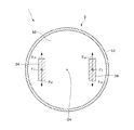
図1は、本発明の水平多関節ロボットおよびロボットシステムの実施形態を示す側面図である。図2は、図1に示すロボットシステムのブロック図である。図3は、図1に示す水平多関節ロボットの第2アームの内部を示す側面図である。図4は、図3中に示す第2アームの内部の一部拡大図である。図5は、図4中A−A線断面図である。図6は、図4中破線で示す領域の拡大断面図である。
<Embodiment>
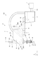
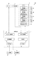
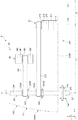
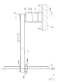
FIG. 1 is a side view showing an embodiment of the horizontal articulated robot and the robot system of the present invention. FIG. 2 is a block diagram of the robot system shown in FIG. FIG. 3 is a side view showing the inside of the second arm of the horizontal articulated robot shown in FIG. FIG. 4 is a partially enlarged view of the inside of the second arm shown in FIG. FIG. 5 is a cross-sectional view taken along the line AA in FIG. FIG. 6 is an enlarged cross-sectional view of a region shown by a broken line in FIG.
また、図1、図3、図4では、説明の便宜上、互いに直交する3軸として、x軸、y軸およびz軸を図示している。また、以下では、x軸に平行な方向を「x軸方向」とも言い、y軸に平行な方向を「y軸方向」とも言い、z軸に平行な方向を「z軸方向」とも言う。また、以下では、図示された各矢印の先端側を「+(プラス)」、基端側を「−(マイナス)」と言い、+x軸方向に平行な方向を「+x軸方向」とも言い、−x軸方向に平行な方向を「−x軸方向」とも言い、+y軸方向に平行な方向を「+y軸方向」とも言い、−y軸方向に平行な方向を「−y軸方向」とも言い、+z軸方向に平行な方向を「+z軸方向」とも言い、−z軸方向に平行な方向を「−z軸方向」とも言う。また、z軸回りの方向およびz軸に平行な軸回りの方向を「u軸方向」とも言う。 Further, in FIGS. 1, 3 and 4, for convenience of explanation, the x-axis, the y-axis and the z-axis are shown as three axes orthogonal to each other. Further, in the following, the direction parallel to the x-axis is also referred to as "x-axis direction", the direction parallel to the y-axis is also referred to as "y-axis direction", and the direction parallel to the z-axis is also referred to as "z-axis direction". Further, in the following, the tip side of each of the illustrated arrows is referred to as "+ (plus)", the proximal end side is referred to as "-(minus)", and the direction parallel to the + x-axis direction is also referred to as "+ x-axis direction". The direction parallel to the −x axis direction is also referred to as “−x axis direction”, the direction parallel to the + y axis direction is also referred to as “+ y axis direction”, and the direction parallel to the −y axis direction is also referred to as “−y axis direction”. The direction parallel to the + z-axis direction is also referred to as "+ z-axis direction", and the direction parallel to the -z-axis direction is also referred to as "-z-axis direction". Further, the direction around the z-axis and the direction around the axis parallel to the z-axis are also referred to as "u-axis directions".
また、以下では、説明の便宜上、図1中の+z軸方向、すなわち、上側を「上」、−z軸方向、すなわち、下側を「下」とも言う。また、ロボットアーム20については、図1中の基台21側を「基端」、その反対側、すなわち、エンドエフェクター7側を「先端」と言う。また、図1中のz軸方向、すなわち、上下方向を「鉛直方向」とし、x軸方向およびy軸方向、すなわち、左右方向を「水平方向」とする。
Further, in the following, for convenience of explanation, the + z-axis direction in FIG. 1, that is, the upper side is referred to as “upper”, and the −z-axis direction, that is, the lower side is also referred to as “lower”. Further, regarding the
図1および図2に示すロボットシステム100は、例えば、電子部品および電子機器等のワーク(対象物)の保持、搬送、組立ておよび検査等の作業で用いられる装置である。ロボットシステム100は、制御装置1と、ロボット2と、エンドエフェクター7と、表示装置41と、入力装置42とを備えている。
The
また、図示の構成では、制御装置1は、ロボット2の外側に配置されているが、これに限定されず、ロボット2に内蔵されていてもよい。
Further, in the illustrated configuration, the
また、図示の構成では、ロボット2と制御装置1とは、ケーブル200で電気的に接続(以下、単に「接続」とも言う)されているが、これに限定されずケーブル200を省略し、無線方式で通信を行うようになっていてもよい。すなわち、ロボット2と制御装置1とは、有線通信で接続されていてもよく、また、無線通信で接続されていてもよい。
Further, in the illustrated configuration, the
ロボット2は、水平多関節ロボット、すなわち、スカラロボットである。
図1に示すように、ロボット2は、基台21と、第1アーム22と、第2アーム23と、作業ヘッドである第3アーム24と、力検出部5と、を備えている。第1アーム22、第2アーム23および第3アーム24等によりロボットアーム20が構成される。
The
As shown in FIG. 1, the
また、ロボット2は、第1アーム22を基台21に対して回転させる駆動ユニット25と、第2アーム23を第1アーム22に対して回転させる駆動ユニット26と、第3アーム24のシャフト241を第2アーム23に対して回転させるu駆動ユニット27と、シャフト241を第2アーム23に対してz軸方向に移動させるz駆動ユニット28と、角速度センサー29とを備えている。
Further, the
図1および図2に示すように、駆動ユニット25は、第1アーム22の筐体220内に内蔵されており、駆動力を発生するモーター251と、モーター251の駆動力を減速する減速機252と、モーター251または減速機252の回転軸の回転角度を検出する位置センサー253とを有している。
As shown in FIGS. 1 and 2, the
駆動ユニット26は、第2アーム23の筐体230に内蔵されており、駆動力を発生するモーター261と、モーター261の駆動力を減速する減速機262と、モーター261または減速機262の回転軸の回転角度を検出する位置センサー263とを有している。
The
u駆動ユニット27は、第2アーム23の筐体230に内蔵されており、駆動力を発生するモーター271と、モーター271の駆動力を減速する減速機272と、モーター271または減速機272の回転軸の回転角度を検出する位置センサー273とを有している。
The
z駆動ユニット28は、第2アーム23の筐体230に内蔵されており、駆動力を発生するモーター281と、モーター281の駆動力を減速する減速機282と、モーター281または減速機282の回転軸の回転角度を検出する位置センサー283とを有している。
The
モーター251、モーター261、モーター271およびモーター281としては、例えば、ACサーボモーター、DCサーボモーター等のサーボモーターを用いることができる。
As the
また、減速機252、減速機262、減速機272および減速機282としては、例えば、遊星ギア型の減速機、波動歯車装置等を用いることができる。また、位置センサー253、位置センサー263、位置センサー273および位置センサー283は、例えば、角度センサーとすることができる。
Further, as the speed reducer 252, the speed reducer 262, the speed reducer 272, and the speed reducer 282, for example, a planetary gear type speed reducer, a wave gear device, or the like can be used. Further, the
駆動ユニット25、駆動ユニット26、u駆動ユニット27およびz駆動ユニット28は、それぞれ、対応する図示しないモータードライバーに接続されており、モータードライバーを介して制御装置1のロボット制御部11により制御される。なお、各減速機は省略されていてもよい。
The
また、角速度センサー29は、第2アーム23に内蔵されている。このため、第2アーム23の角速度を検出することができる。この検出した角速度の情報に基づいて、制御装置1は、ロボット2の制御を行う。また、角速度センサー29は、駆動ユニット26〜28よりも−y軸側、すなわち、基台21の遠位側に設置されている。
Further, the
基台21は、例えば、図示しない床面にボルト等によって固定されている。基台21の上端部には第1アーム22が連結されている。第1アーム22は、基台21に対して鉛直方向に沿う第1軸O1回りに回転可能となっている。第1アーム22を回転させる駆動ユニット25が駆動すると、第1アーム22が基台21に対して第1軸O1回りに水平面内で回転する。また、位置センサー253により、基台21に対する第1アーム22の回転量が検出できるようになっている。
The
また、第1アーム22の先端部には、第2アーム23が連結されている。第2アーム23は、第1アーム22に対して鉛直方向に沿う第2軸O2回りに回転可能となっている。第1軸O1の軸方向と第2軸O2の軸方向とは同一である。すなわち、第2軸O2は、第1軸O1と平行である。第2アーム23を回転させる駆動ユニット26が駆動すると、第2アーム23が第1アーム22に対して第2軸O2回りに水平面内で回転する。また、位置センサー263により、第1アーム22に対する第2アーム23の駆動、具体的には、回転量が検出できるようになっている。
A
また、第2アーム23は、底板231、天板232およびこれらを連結している側壁233を有する筐体230を有している。この筐体230の内部、すなわち、底板231上には、駆動ユニット26、u駆動ユニット27、z駆動ユニット28および角速度センサー29が+y軸側からこの順で並んでいる。
Further, the
また、筐体230は、天板232と側壁233との間に位置する傾斜部234を有している。この傾斜部234は、天板232の−y軸側に設けられている。また、この傾斜部234は、z軸に対して傾斜して設けられている。
Further, the
また、図3および図4に示すように、第2アーム23の先端部には、第3アーム24が設置されている。第3アーム24は、シャフト241と、シャフト241を回転可能に支持する回転支持部材242とを有する。
Further, as shown in FIGS. 3 and 4, a
シャフト241は、第2アーム23に対して、鉛直方向に沿う第3軸O3回りに回転可能であり、かつ、上下方向に移動(昇降)可能となっている。このシャフト241は、ロボットアーム20の第3アームであり、ロボットアーム20の最も先端のアームである。
The
また、シャフト241の長手方向の途中には、ボールねじナット243と、スプラインナット244とが設置されており、シャフト241は、これらによって支持されている。これらボールねじナット243およびスプラインナット244は、この順で+z軸側から離間して配置されている。
Further, a
ボールねじナット243は、内輪243Aと、内輪243Aの外周側に同心的に配置された外輪243Bとを有する。これら内輪243Aおよび外輪243Bの間には、図示しない複数のボールが配置されており、ボールの移動とともに内輪243Aおよび外輪243Bは、互いに相対的に回転する。
The
また、内輪243Aは、外輪243Bから露出した部分を有し、この露出した部分に後述するベルト284が掛け回されている。また、内輪243Aは、その内部にシャフト241を挿通し、後述するように、シャフト241をz軸方向に沿って移動可能に支持している。
Further, the
スプラインナット244は、内輪244Aと、内輪244Aの外周側に同心的に配置された外輪244Bとを有する。これら内輪244Aおよび外輪244Bの間には、図示しない複数のボールが配置されており、ボールの移動とともに内輪244Aおよび外輪244Bは、互いに相対的に回転する。
The
また、内輪244Aは、外輪244Bから露出した部分を有し、この露出した部分に後述するベルト274が掛け回されている。また、内輪244Aは、その内部にシャフト241を挿通し、シャフト241をz軸回り、すなわち、u軸方向に回転可能に支持している。
Further, the
また、スプラインナット244の−z軸側には、回転支持部材242が設置されている。この回転支持部材242は、外筒245と、外筒245の内側に設けられた回転体246と、を有する。外筒245は、第2アーム23の筐体230内の底板231に固定されている。一方、回転体246は、シャフト241には固定されているが、シャフト241とともにz軸回りに回転可能に外筒245に支持されている。
Further, a
シャフト241を回転させるu駆動ユニット27が駆動すると、シャフト241は、z軸回りに正逆回転、すなわち、回転する。また、位置センサー273により、第2アーム23に対するシャフト241の回転量が検出できるようになっている。
When the
また、シャフト241をz軸方向に移動させるz駆動ユニット28が駆動すると、シャフト241は、上下方向、すなわち、z軸方向に移動する。また、位置センサー283により、第2アーム23に対するシャフト241のz軸方向の移動量が検出できるようになっている。
Further, when the
また、シャフト241の先端部には、各種のエンドエフェクターが着脱可能に連結される。エンドエフェクターとしては、特に限定されず、例えば、被搬送物を把持するもの、被加工物を加工するもの、検査に使用するもの等が挙げられる。本実施形態では、エンドエフェクター7が着脱可能に連結される。エンドエフェクター7については、後に詳述する。
In addition, various end effectors are detachably connected to the tip of the
なお、エンドエフェクター7は、本実施形態では、ロボット2の構成要素になっていないが、エンドエフェクター7の一部または全部がロボット2の構成要素になっていてもよい。また、エンドエフェクター7は、本実施形態では、ロボットアーム20の構成要素になっていないが、エンドエフェクター7の一部または全部がロボットアーム20の構成要素になっていてもよい。
Although the
図1に示すように、エンドエフェクター7は、シャフト241に取り付けられた取り付け部71と、取り付け部71に設けられたモーター72と、モーター72の回転軸に、着脱可能に同心的に取り付けられたねじ用限界ゲージ3とを有している。このエンドエフェクター7は、シャフト241の先端部に着脱可能に連結される。また、シャフト241の中心軸、すなわち、第3軸O3と、モーター72の回転軸と、ねじ用限界ゲージ3の中心軸とは、一致している。すなわち、第3軸O3の軸方向から見て、第3軸O3と、モーター72と、ねじ用限界ゲージ3とは重なっている。
As shown in FIG. 1, the
また、ねじ用限界ゲージ3は、ねじゲージの1例であり、柱状の把持部31と、把持部31の一端部に設けられ、雄ねじが形成された通り側ゲージ32と、把持部31の他端部に設けられ、雄ねじが形成された止まり側ゲージ33とを有している。このねじ用限界ゲージ3は、通り側ゲージ32を使用する場合は、止まり側ゲージ33が設けられた把持部31の端部をモーター72の回転軸に取り付け、通り側ゲージ32を先端側に配置する。また、止まり側ゲージ33を使用する場合は、通り側ゲージ32が設けられた把持部31の端部をモーター72の回転軸に取り付け、止まり側ゲージ33を先端側に配置する。
The
また、モーター72としては、特に限定されないが、例えば、ACサーボモーター、DCサーボモーター等のサーボモーター、ステッピングモーター等が用いられる。
The
また、エンドエフェクター7は、モーター72の回転軸の回転角度を検出する図示しない角度センサーを有しており、その位置センサーにより、モーター72の回転軸の回転角度が検出できるようになっている。
Further, the
このエンドエフェクター7では、モーター72の回転軸とねじ用限界ゲージ3との間に歯車やベルト等の動力伝達機構が介在している場合に比べて、バックラッシュによる回転精度の低下を抑制することができる。
In this
なお、ねじ用限界ゲージ3は、このような構成のものに限定されず、例えば、通り側ゲージのみを有するねじ用限界ゲージと、止まり側ゲージのみを有するねじ用限界ゲージとを付け替えて使用する構成のものであってもよい。
The
また、本実施形態では、エンドエフェクター7は、ロボットアーム20に対して着脱可能であるが、これに限定されず、例えば、エンドエフェクター7は、ロボットアーム20から離脱不能になっていてもよい。
Further, in the present embodiment, the
また、力検出部5は、モーター271の駆動による反力を検出するものであり、その検出が制御装置1に送信される。
Further, the
また、力検出部5は、後述するように、第2アーム23、すなわち、ベース部230Aと、モーター271との間に設けられている。これにより、モーター271の駆動により生じる反力が力検出部5に伝達される。よって、この反力を検出することができる。
Further, as will be described later, the
図2に示すように、制御装置1は、ロボット制御部11と、モーター制御部12(エンドエフェクター制御部)と、表示制御部13と、記憶部14と、受付部15と、判定部16とを備えており、ロボット2、エンドエフェクター7のモーター72および表示装置41等、ロボットシステム100の各部の駆動をそれぞれ制御する。
As shown in FIG. 2, the
また、制御装置1は、ロボット制御部11と、モーター制御部12と、表示制御部13と、記憶部14と、受付部15と、判定部16との間で、それぞれ、通信可能に構成されている。すなわち、ロボット制御部11と、モーター制御部12と、表示制御部13と、記憶部14と、受付部15と、判定部16とは、互いに、有線または無線通信で接続されている。
Further, the
また、制御装置1には、ロボット2と、表示装置41と、入力装置42と、エンドエフェクター7とが、それぞれ、有線または無線通信で接続されている。
Further, the
ロボット制御部11は、ロボット2の駆動、すなわち、ロボットアーム20等の駆動を制御する。ロボット制御部11は、OS等のプログラムがインストールされたコンピューターである。このロボット制御部11は、例えば、プロセッサとしてのCPUと、RAMと、プログラムが記憶されたROMとを有する。また、ロボット制御部11の機能は、例えば、CPUにより各種プログラムを実行することにより実現することができる。
The robot control unit 11 controls the drive of the
また、ロボット制御部11は、力検出部5と電気的に接続されており、力検出部5から受け取った電気信号を、第3アーム24に加わった外力とみなし、力に変換する。すなわち、力検出部5によって検出されたモーター271の駆動の反力の変化量から、第3アーム24に加わった外力に換算する。そしてこの算出された外力に基づいて、第3アーム24をu軸方向に駆動するu駆動ユニット27のモーター271への指令値を制御するとともに、第3アーム24をz軸方向に駆動するz駆動ユニット28のモーター281への指令値を制御する。これにより、加わった外力に応じて、第3アーム24をu軸方向およびz軸方向に移動させることができる。よって、例えば、ネジ締め作業を力制御により行うことができたり、第3アーム24に閾値を超える外力が加わると、エンドエフェクター7を+z軸方向に退避したりすることができる。また、外力が加わっていなくても、モーター271を回転させる際の最初の加速時、定常運転時、減速時のそれぞれの制御に用いることもできる。
Further, the robot control unit 11 is electrically connected to the
このように、ロボットシステム100では、力検出部5によって検出された反力に基づいて、第3アーム24に加わる第3軸方向O3の力を制御する。
In this way, the
モーター制御部12は、モーター72の駆動を制御する。モーター制御部12は、OS等のプログラムがインストールされたコンピューターである。このモーター制御部12は、例えば、プロセッサとしてのCPUと、RAMと、プログラムが記憶されたROMとを有する。また、モーター制御部12の機能は、例えば、CPUにより各種プログラムを実行することにより実現することができる。
The motor control unit 12 controls the drive of the
表示制御部13は、表示装置41にウィンドウ等の各種の画面や文字等を表示させる機能を有している。すなわち、表示制御部13は、表示装置41の駆動を制御する。この表示制御部13の機能は、例えばGPU等により実現することができる。
The
記憶部14は、各種の情報(データやプログラム等を含む)を記憶する機能を有する。この記憶部14は、制御プログラム等を記憶する。記憶部14の機能は、ROM等のいわゆる外部記憶装置(図示せず)によって実現することができる。 The storage unit 14 has a function of storing various types of information (including data, programs, and the like). The storage unit 14 stores a control program and the like. The function of the storage unit 14 can be realized by a so-called external storage device (not shown) such as a ROM.
受付部15は、入力装置42からの入力を受け付ける機能を有している。この受付部15の機能は、例えばインターフェース回路によって実現することができる。なお、例えばタッチパネルを用いる場合には、受付部15は、ユーザーの指のタッチパネルへの接触等を検知する入力検知部としての機能を有する。
The
表示装置41は、例えば、液晶ディスプレイ、ELディスプレイ等で構成された図示しないモニターを備えており、例えば、ウィンドウ等の各種の画面等を含む各種の画像や文字等を表示する機能を有する。 The display device 41 includes, for example, a monitor (not shown) composed of a liquid crystal display, an EL display, or the like, and has a function of displaying various images, characters, or the like including various screens such as windows.
入力装置42は、例えば、マウスやキーボード等で構成されている。したがって、ユーザーは、入力装置42を操作することで、制御装置1に対して各種の処理等の指示を行うことができる。
The
具体的には、ユーザーは、表示装置41に表示されるウィンドウ等の各種画面に対して入力装置42のマウスでクリックする操作や、入力装置42のキーボードで文字や数字等を入力する操作により、制御装置1に対する指示を行うことができる。
Specifically, the user can click on various screens such as windows displayed on the display device 41 with the mouse of the
なお、本実施形態では、表示装置41および入力装置42の代わりに、表示装置41および入力装置42を兼ね備えた表示入力装置を設けてもよい。表示入力装置としては、例えば静電式タッチパネルや感圧式タッチパネル等のタッチパネルを用いることができる。また、入力装置42は、音声等の音を認識する構成であってもよい。
In the present embodiment, instead of the display device 41 and the
次に、第2アーム23の内部について説明する。
ロボット2では、図3に示すように、第2アーム23の筐体230内に、第3アーム24をz軸回りに回転させるu駆動ユニット27と、第3アーム24をz軸方向に移動させるz駆動ユニット28と、ベルト274と、ベルト284と、が設けられている。
Next, the inside of the
In the
また、第2アーム23の筐体230は、ベース部230Aの+z軸側を覆うカバー部材230Bと、を有している。ベース部230Aは、剛体であり、例えば、金属材料、各種硬質樹脂材料等で構成されている。なお、ベース部230Aが第2アーム230を構成するため、以下では、第2アーム230をベース部230Aとも言う。
Further, the
図3に示すように、u駆動ユニット27は、前述したモーター271、減速機272および位置センサー273に加え、プーリー275を有する。これらは、プーリー275、減速機272およびモーター271の順で+z軸側から配置され、ベース部230Aに固定されている。プーリー275は、減速機272のコアに固定されており、モーター271の回転力が減速機272で減速されて、プーリー275に伝達される。
As shown in FIG. 3, the
また、プーリー275は、ベルト274によってシャフト241に設けられたスプラインナット244の内輪244Aと連結されている。ベルト274は、プーリー275および内輪244Aに掛け回された無端ベルトであり、その内側、すなわち、プーリー275および内輪244A側に図示しない歯を有する。ベルト274の歯が、プーリー275および内輪244Aの露出した部分の図示しない歯とそれぞれ噛合している。
Further, the
このようなu駆動ユニット27では、モーター271の回転力が減速機272およびプーリー275を介してベルト274に伝達され、ベルト274が回転する。このベルト274の回転により、その回転力がスプラインナット244を介してシャフト241に伝達される。この回転力が内輪244Aの内周部およびシャフト241のスプライン溝を介してシャフト241に伝達され、シャフト241がu軸方向に移動する、すなわち、回転することができる。
In such
このように、第3アーム24は、シャフト241と、シャフト241に設けられたスプラインナット244と、を有している。また、ロボット2は、モーター271と、スプラインナット244とを連結するベルト274をさらに有する。これにより、シャフト241に加わった外力が、ベルト274、スプラインナット244およびモーター271を介して力検出部5に伝達される。よって、力検出部5がシャフト241に加わった外力を検出することができる。
As described above, the
図3に示すように、z駆動ユニット28は、前述したモーター281、減速機282および位置センサー283に加え、プーリー285を有する。これらは、モーター281、プーリー285および減速機282の順で+z軸側から配置されている。プーリー285は、減速機282のコアに固定されており、モーター281の回転力が減速機282で減速されて、プーリー285に伝達される。また、減速機282は、図示しないスペーサーを介してベース部230Aに固定されている。
As shown in FIG. 3, the
また、プーリー285は、ベルト284によってシャフト241に設けられたボールねじナット243の内輪243Aの露出した部分と連結されている。ベルト284は、プーリー285および内輪243Aに掛け回された無端ベルトであり、その内側、すなわち、プーリー285および内輪243A側に図示しない歯を有する。ベルト284の歯が、プーリー285および内輪243Aの図示しない歯とそれぞれ噛合している。
Further, the
このようなz駆動ユニット28では、モーター281の回転力が減速機282およびプーリー285を介してベルト284に伝達され、ベルト284が回転する。このベルト284の回転により、その回転力がボールねじナット243の内輪243Aを介してシャフト241に伝達される。この回転力が内輪243Aの内周部およびシャフト241のボールねじ溝によって方向が変換され、シャフト241がz軸方向に移動する、すなわち、上下動することができる。
In such
次に、力検出部5について説明する。
図3および図4に示すように、力検出部5は、前述したように第3アーム24に加わる力を検出するセンサーである。本実施形態では、ボールねじナット243と、ベース部230Aとの間に設けられており、これらに固定され、挟持されている。また、図6に示すように、力検出部5は、第1プレート51と、第2プレート52と、第1プレート51と第2プレート52との間に配置された筒状部53と、複数、本実施形態では、2つの素子54とを有する。また、2つの素子54は、第1プレート51と、第2プレート52との間で挟持されている。
Next, the
As shown in FIGS. 3 and 4, the
このように力検出部5は、第1プレート51と、第2プレート52と、第1プレート51と第2プレート52とに挟持されている複数、本実施形態では、2つの素子54とを有する。これにより、後述するように、素子54は、モーター271の回転により生じる反力を検出することができる。
As described above, the
第1プレート51は、円板状をなし、その+z軸側の面がモーター271の筐体に固定されている。図示の構成では、第1プレート51およびモーター271は、ねじ、ビス等の固定部材8を介して固定されている。第2プレート52は、円板状をなし、その−z軸側の面がベース部230Aの+z軸側の面に固定されている。図示の構成では、第2プレート52およびベース部230Aは、ねじ、ビス等の固定部材9を介して固定されている。
The
筒状部53は、本実施形態では、円筒状をなし、素子54を保護する機能を有する。
図5に示すように、各素子54は、モーター271の出力軸O4を介して対向配置されている。すなわち、第3軸O3の軸方向から見て、モーター271の出力軸O4は、複数の素子54の間にある。これにより、各素子54に加わる力が可及的に均一になり、正確に力を検出することができる。
In the present embodiment, the
As shown in FIG. 5, each
なお、素子54の個数は、図示のような2つに限定されず、例えば、3つ以上であってもよいが、素子54の数は、4つであるのが好ましい。この場合、各素子54は、出力軸O4の周方向に沿って等間隔で設けられている、すなわち、出力軸O4を介して配置されている対が2対になるように配置されるのが好ましい。
The number of
各素子54は、例えば、水晶等の圧電体で構成され、外力を受けると電荷を出力するものを用いることができる。また、制御装置1は、この電荷量に応じて受けた外力に変換することができる。また、このような圧電体であると、設置する向きに応じて、外力を受けた際に電荷を発生させることができる向きを調整可能である。本実施形態では、各素子54は、図5に示すように、鉛直方向の成分の力Fzと、z軸回り、すなわち、u軸方向の力Fuとを検出することができる。
Each
このような力検出部5は、前述したように、第1プレート51がモーター271に固定され、第2プレート52がベース部230Aに固定されている。このような構成により、u駆動ユニット27のモーター271が駆動し、内部の図示しないローターが回転すると、その反力がモーター271の筐体を介して力検出部5に伝達される。そして、この伝達された力を力検出部5が検出し、反力の情報を電気信号に変換して図2に示す制御装置1のロボット制御部11に送信することにより、後述するような制御が行われる。よって、力検出部5の検出結果に基づいて、第3アーム24を駆動することができる。
In such a
特に、従来では、第3アーム24に相当するアームの先端に力検出部を設置していた。しかしながら、このような構成では、アームの実質的な可動部分、すなわち、アームの付け根からエンドエフェクターまでの長さが長くなってしまう。これに対し、本発明では、第2アーム23とモーター271との間に力検出部5を設置し、モーター271の駆動による反力を検出する構成となっている。すなわち、力検出部5を第2アーム23に内蔵し、第3アーム24に力検出部5が設置されるのを省略した構成となっている。これにより。第3アーム24の実質的な可動部分を短くすることができる。よって、例えば、第3アーム24を最大限まで−z軸側に移動させたときのエンドエフェクター7の先端が、従来よりも−z軸側に位置することとなり、小型化を実現することができる。さらに、従来に比べ、第3アーム24の可搬重量をより十分に確保することができる。
In particular, conventionally, a force detecting unit has been installed at the tip of an arm corresponding to the
また、力検出部5は、第2軸O2と第3軸O3との間に設置されている。すなわち、力検出部5は、第3軸O3から第2軸O2側に偏在している。これにより、力検出部5が第3アーム24に設けられている構成と比べ、第2アーム23の先端側の重量を軽くすることができる。よって、第2アーム23を駆動する際の慣性モーメントを小さくすることができ、第2アーム23を駆動する際の駆動力を比較的小さくすることができるとともに、第2アーム23を駆動するモーター261の負荷を軽減することができる。
Further, the
また、図3に示すように、第2軸O2から出力軸O4までの距離L2は、第3軸O3から出力軸O4までの距離L1よりも小さいのが好ましい。これにより、前述した第2アーム23を駆動するモーター261の負荷を軽減することができるという効果をより一層顕著に得ることができる。
Further, as shown in FIG. 3, the distance L2 from the second axis O2 to the output axis O4 is preferably smaller than the distance L1 from the third axis O3 to the output axis O4. As a result, the effect that the load of the
以上説明したように、ロボット2は、基台21と、基台21に接続され、第1軸O1回りに回動する第1アーム22と、第1アーム22に接続され、第1軸O1と平行な第2軸O2回りに回動する第2アーム23と、第2アーム23に接続され、第1軸O1と平行な第3軸O3回りに回動し、かつ、第3軸O3に沿って移動する第3アーム24と、第2アーム23に設けられ、第3アーム24を駆動するモーター271と、モーター271と第2アーム23との間に設けられ、モーター271の駆動による反力を検出する力検出部5と、を備える。これにより、力検出部5を第2アーム23に内蔵し、第3アーム24に力検出部5が設置されるのを省略した構成とすることができる。よって、第3アーム24の実質的な可動部分を短くすることができ、小型化を実現することができる。
As described above, the
また、ロボットシステム100は、前述したように、ロボット2と、力検出部5によって検出された、モーター271の駆動による反力に基づいて、第3アーム24の駆動を制御する制御部としての制御装置1と、を備える。これにより、前述したロボット2の利点を享受しつつ、加わった外力に応じて、第3アーム24の動作を制御することができる。例えば、モーター271を回転させる際の最初の加速時、定常運転時、減速時のそれぞれの制御を行うことができる。また、力検出部5によって検出されたモーター271の駆動の反力の変化量から、第3アーム24に加わった外力(特に、z軸方向の外力)に換算し、この外力に応じて、第3アーム24をu軸方向およびz軸方向に移動させたり、エンドエフェクター7の力制御に用いることもできる。
Further, as described above, the
以上、本発明の水平多関節ロボットおよびロボットシステムを図示の実施形態に基づいて説明したが、本発明は、これに限定されるものではなく、各部の構成は、同様の機能を有する任意の構成のものに置換することができる。また、他の任意の構成物が付加されていてもよい。 Although the horizontal articulated robot and the robot system of the present invention have been described above based on the illustrated embodiment, the present invention is not limited to this, and the configuration of each part is an arbitrary configuration having the same function. Can be replaced with one. Moreover, other arbitrary components may be added.
また、前記実施形態では、ロボットアームの回転軸の数は、3つであるが、本発明では、これに限定されず、ロボットアームの回転軸の数は、例えば、2つ、または、4つ以上でもよい。すなわち、前記実施形態では、アームの数は、3つであるが、本発明では、これに限定されず、アームの数は、例えば、2つ、または、4つ以上でもよい。 Further, in the above-described embodiment, the number of rotation axes of the robot arm is three, but the present invention is not limited to this, and the number of rotation axes of the robot arm is, for example, two or four. The above may be sufficient. That is, in the above embodiment, the number of arms is three, but in the present invention, the number of arms is not limited to this, and the number of arms may be, for example, two or four or more.
また、前記実施形態では、モーター271と力検出部5とが固定されている構成であったが、本発明ではこれに限定されず、例えば、モーター271と力検出部5との間に例えば減速機等が介在していてもよい。
Further, in the above-described embodiment, the
また、前記実施形態では、モーター271とベース部230Aとの間に力検出部5が設けられている構成であったが、本発明ではこれに限定されず、例えば、モーター281とベース部230Aとの間に設けられていてもよい。この場合であっても、本発明の効果が得られる。また、モーター271とベース部230Aとの間、モーター281とベース部230Aとの間の双方に設けられていてもよい。
Further, in the above embodiment, the
100…ロボットシステム、1…制御装置、2…ロボット、20…ロボットアーム、21…基台、22…第1アーム、23…第2アーム、24…第3アーム、25…駆動ユニット、26…駆動ユニット、27…u駆動ユニット、28…z駆動ユニット、29…角速度センサー、3…ねじ用限界ゲージ、31…把持部、32…通り側ゲージ、33…止まり側ゲージ、5…力検出部、51…第1プレート、52…第2プレート、53…筒状部、54…素子、7…エンドエフェクター、8…固定部材、9…固定部材、11…ロボット制御部、12…モーター制御部、13…表示制御部、14…記憶部、15…受付部、16…判定部、41…表示装置、42…入力装置、71…取り付け部、72…モーター、200…ケーブル、220…筐体、230…筐体、230A…ベース部、230B…カバー部材、230C…凹部、231…底板、232…天板、233…側壁、234…傾斜部、241…シャフト、242…回転支持部材、243…ボールねじナット、243A…内輪、243B…外輪、244…スプラインナット、244A…内輪、244B…外輪、245…外筒、246…回転体、251…モーター、252…減速機、253…位置センサー、261…モーター、262…減速機、263…位置センサー、271…モーター、272…減速機、273…位置センサー、274…ベルト、275…プーリー、281…モーター、282…減速機、283…位置センサー、284…ベルト、285…プーリー、Fu…力、Fz…力、O1…第1軸、O2…第2軸、O3…第3軸、O4…出力軸 100 ... Robot system, 1 ... Control device, 2 ... Robot, 20 ... Robot arm, 21 ... Base, 22 ... 1st arm, 23 ... 2nd arm, 24 ... 3rd arm, 25 ... Drive unit, 26 ... Drive Unit, 27 ... u drive unit, 28 ... z drive unit, 29 ... angular speed sensor, 3 ... screw limit gauge, 31 ... grip part, 32 ... street side gauge, 33 ... stop side gauge, 5 ... force detector, 51 ... 1st plate, 52 ... 2nd plate, 53 ... Cylindrical part, 54 ... Element, 7 ... End effector, 8 ... Fixed member, 9 ... Fixed member, 11 ... Robot control unit, 12 ... Motor control unit, 13 ... Display control unit, 14 ... storage unit, 15 ... reception unit, 16 ... judgment unit, 41 ... display device, 42 ... input device, 71 ... mounting unit, 72 ... motor, 200 ... cable, 220 ... housing, 230 ... housing Body, 230A ... Base part, 230B ... Cover member, 230C ... Recessed part, 231 ... Bottom plate, 232 ... Top plate, 233 ... Side wall, 234 ... Inclined part, 241 ... Shaft, 242 ... Rotation support member, 243 ... Ball screw nut, 243A ... Inner ring, 243B ... Outer ring, 244 ... Spline nut, 244A ... Inner ring, 244B ... Outer ring, 245 ... Outer cylinder, 246 ... Rotating body, 251 ... Motor, 252 ... Reducer, 253 ... Position sensor, 261 ... Motor, 262 ... reducer, 263 ... position sensor, 271 ... motor, 272 ... reducer, 273 ... position sensor, 274 ... belt, 275 ... pulley, 281 ... motor, 282 ... reducer, 283 ... position sensor, 284 ... belt, 285 ... Pulley, Fu ... Force, Fz ... Force, O1 ... 1st axis, O2 ... 2nd axis, O3 ... 3rd axis, O4 ... Output axis
Claims (5)
前記基台に接続され、第1軸回りに回動する第1アームと、
前記第1アームに接続され、前記第1軸と平行な第2軸回りに回動する第2アームと、
前記第2アームに接続され、前記第1軸と平行な第3軸回りに回動し、かつ、前記第3軸に沿って移動する第3アームと、
前記第2アームに設けられ、前記第3アームを駆動するモーターと、
前記モーターと前記第2アームとの間に設けられ、前記モーターの駆動による反力を検出する力検出部と、を備えることを特徴とする水平多関節ロボット。 Base and
A first arm connected to the base and rotating around the first axis,
A second arm connected to the first arm and rotating around a second axis parallel to the first axis,
A third arm connected to the second arm, rotating around a third axis parallel to the first axis, and moving along the third axis.
A motor provided on the second arm and driving the third arm,
A horizontal articulated robot provided between the motor and the second arm and provided with a force detecting unit for detecting a reaction force generated by driving the motor.
前記第1プレートは、前記モーターに固定され、
前記第2プレートは、前記第2アームに固定されている請求項1に記載の水平多関節ロボット。 The force detecting unit includes a first plate, a second plate, and a plurality of elements sandwiched between the first plate and the second plate.
The first plate is fixed to the motor and
The horizontal articulated robot according to claim 1, wherein the second plate is fixed to the second arm.
前記力検出部によって検出された前記反力に基づいて、前記第3アームの駆動を制御する制御部と、を備えることを特徴とするロボットシステム。 The horizontal articulated robot according to any one of claims 1 to 4,
A robot system including a control unit that controls driving of the third arm based on the reaction force detected by the force detecting unit.
Priority Applications (4)
| Application Number | Priority Date | Filing Date | Title |
|---|---|---|---|
| JP2019068684A JP2020163548A (en) | 2019-03-29 | 2019-03-29 | Horizontal articulated robot and robot system |
| CN202010223324.7A CN111745633B (en) | 2019-03-29 | 2020-03-26 | Horizontal multi-joint robot and robot system |
| EP20166305.1A EP3715060B1 (en) | 2019-03-29 | 2020-03-27 | Horizontal articulated robot and robot system |
| US16/832,272 US11458625B2 (en) | 2019-03-29 | 2020-03-27 | Horizontal articulated robot and robot system |
Applications Claiming Priority (1)
| Application Number | Priority Date | Filing Date | Title |
|---|---|---|---|
| JP2019068684A JP2020163548A (en) | 2019-03-29 | 2019-03-29 | Horizontal articulated robot and robot system |
Publications (2)
| Publication Number | Publication Date |
|---|---|
| JP2020163548A true JP2020163548A (en) | 2020-10-08 |
| JP2020163548A5 JP2020163548A5 (en) | 2022-03-08 |
Family
ID=70108043
Family Applications (1)
| Application Number | Title | Priority Date | Filing Date |
|---|---|---|---|
| JP2019068684A Pending JP2020163548A (en) | 2019-03-29 | 2019-03-29 | Horizontal articulated robot and robot system |
Country Status (4)
| Country | Link |
|---|---|
| US (1) | US11458625B2 (en) |
| EP (1) | EP3715060B1 (en) |
| JP (1) | JP2020163548A (en) |
| CN (1) | CN111745633B (en) |
Citations (3)
| Publication number | Priority date | Publication date | Assignee | Title |
|---|---|---|---|---|
| JPH07100781A (en) * | 1993-10-05 | 1995-04-18 | Ricoh Co Ltd | Articulated robot |
| JP2011101907A (en) * | 2009-11-10 | 2011-05-26 | Seiko Epson Corp | Scalar robot |
| JP2017177263A (en) * | 2016-03-29 | 2017-10-05 | セイコーエプソン株式会社 | Robot, robot control device, and robot system |
Family Cites Families (44)
| Publication number | Priority date | Publication date | Assignee | Title |
|---|---|---|---|---|
| US4573362A (en) * | 1984-07-09 | 1986-03-04 | Eaton Corporation | Multi-axis load transducer |
| DE3786860T2 (en) * | 1986-03-14 | 1993-11-11 | Fanuc Ltd | CONTROL DEVICE FOR A ROBOT. |
| US4836034A (en) * | 1986-07-15 | 1989-06-06 | Ricoh Company, Ltd. | Force sensing apparatus |
| US4894908A (en) * | 1987-08-20 | 1990-01-23 | Gmf Robotics Corporation | Method for automated assembly of assemblies such as automotive assemblies and system utilizing same |
| US4951517A (en) * | 1987-10-28 | 1990-08-28 | Canon Kabushiki Kaisha | Rotational driving apparatus with frictional engagement and robot using the same |
| US4821584A (en) * | 1988-03-15 | 1989-04-18 | The United States Of America As Represented By The United States Department Of Energy | Piezoelectric film load cell robot collision detector |
| US5144211A (en) * | 1989-01-31 | 1992-09-01 | Staubli International Ag | Multiaxis robot controller having workpoint torque control |
| US5425133A (en) * | 1990-01-24 | 1995-06-13 | Canon Kabushiki Kaisha | Robot apparatus with an electrical driver for controlling a detachable rotor hand |
| US5203748A (en) * | 1990-05-09 | 1993-04-20 | Canon Kabushiki Kaisha | Rotary driving system and robot operating thereon |
| JP2826556B2 (en) * | 1990-11-28 | 1998-11-18 | キヤノン株式会社 | Industrial robot |
| JPH04256590A (en) | 1991-02-04 | 1992-09-11 | Fujitsu Ltd | Control method for robot |
| IT1251017B (en) * | 1991-05-21 | 1995-04-28 | Ugo Crippa | MECHANISM TO CARRY OUT PREFIXED TRAJECTORIES SIMILAR TO ELLIPTICAL |
| DE29514892U1 (en) * | 1995-09-16 | 1995-11-23 | Zeiss Carl Fa | Collision protection for the measuring arm of a coordinate measuring machine |
| CH690865A5 (en) * | 1996-05-09 | 2001-02-15 | Kk Holding Ag | Force and torque measurement arrangement. |
| US6212968B1 (en) * | 1998-07-29 | 2001-04-10 | Janome Sewing Machine Co., Ltd, | SCARA robot |
| JP2001096480A (en) * | 1999-09-28 | 2001-04-10 | Tatsumo Kk | Horizontal articulated industrial robot |
| DE10349452A1 (en) * | 2003-10-23 | 2005-05-25 | Bosch Rexroth Ag | Scara-type robot |
| JP4203051B2 (en) * | 2005-06-28 | 2008-12-24 | 本田技研工業株式会社 | Force sensor |
| JP2008213129A (en) * | 2007-03-07 | 2008-09-18 | Seiko Epson Corp | General-purpose cell for production system and production system using general-purpose cell |
| DE102008023836B4 (en) * | 2007-05-17 | 2020-10-29 | Denso Wave Inc. | Robot with a linearly movable support part that is attached to a gripping device |
| JP5235376B2 (en) * | 2007-10-05 | 2013-07-10 | 川崎重工業株式会社 | Robot target position detector |
| CN103328161B (en) * | 2011-01-31 | 2015-08-19 | 丰田自动车株式会社 | Multi-joint arm robot and control method thereof |
| JP2013066954A (en) * | 2011-09-21 | 2013-04-18 | Seiko Epson Corp | Robot and robot control method |
| JP6008112B2 (en) * | 2012-10-23 | 2016-10-19 | セイコーエプソン株式会社 | Horizontal articulated robot |
| TWI546170B (en) * | 2012-12-24 | 2016-08-21 | 台達電子工業股份有限公司 | Methods and apparatus for driving a robot |
| JP2015071214A (en) * | 2013-10-04 | 2015-04-16 | キヤノン株式会社 | Force sensor protection mechanism, end effector, and robot arm |
| CN104596675B (en) * | 2013-10-31 | 2019-05-14 | 精工爱普生株式会社 | Sensor element, force checking device, robot, electronic component handling apparatus |
| TW201521979A (en) * | 2013-12-10 | 2015-06-16 | Hiwin Tech Corp | SCARA Robot |
| JP6252241B2 (en) * | 2014-02-27 | 2017-12-27 | セイコーエプソン株式会社 | Force detection device and robot |
| JP6248709B2 (en) * | 2014-03-04 | 2017-12-20 | セイコーエプソン株式会社 | Force detection device and robot |
| US9718187B2 (en) * | 2014-06-11 | 2017-08-01 | Canon Kabushiki Kaisha | Robot controlling method, robot apparatus, program, recording medium, and method for manufacturing assembly component |
| JP6193816B2 (en) * | 2014-06-20 | 2017-09-06 | ファナック株式会社 | Articulated robot with arm retracting function |
| JP6592969B2 (en) * | 2015-06-02 | 2019-10-23 | セイコーエプソン株式会社 | Mating method |
| DE102015214170A1 (en) * | 2015-07-27 | 2017-02-02 | Kuka Roboter Gmbh | Robot with a force measuring device |
| JP1581639S (en) * | 2016-02-26 | 2017-07-18 | ||
| US10580681B2 (en) * | 2016-07-10 | 2020-03-03 | Yaskawa America Inc. | Robotic apparatus and method for transport of a workpiece |
| US10780535B2 (en) * | 2016-07-21 | 2020-09-22 | Delta Electronics, Inc. | Automatic screw tightening module and robot manipulator employing same |
| JP2018075672A (en) * | 2016-11-10 | 2018-05-17 | セイコーエプソン株式会社 | Control device, robot, and robot system |
| CN107457777A (en) * | 2017-01-16 | 2017-12-12 | 王晶红 | A kind of horizontal articulated SCARA types cooperation robot |
| JP2018119923A (en) * | 2017-01-27 | 2018-08-02 | セイコーエプソン株式会社 | Force detector and robot |
| JP2018189385A (en) * | 2017-04-28 | 2018-11-29 | セイコーエプソン株式会社 | Force detection device and robot |
| JP2019012012A (en) * | 2017-06-30 | 2019-01-24 | セイコーエプソン株式会社 | Force detection device and robot |
| JP6983024B2 (en) | 2017-10-04 | 2021-12-17 | ローム株式会社 | Insulated DC / DC converter, its primary controller, power adapter and electronics |
| JP6690626B2 (en) * | 2017-10-31 | 2020-04-28 | 株式会社安川電機 | Robot system and robot evacuation method |
-
2019
- 2019-03-29 JP JP2019068684A patent/JP2020163548A/en active Pending
-
2020
- 2020-03-26 CN CN202010223324.7A patent/CN111745633B/en active Active
- 2020-03-27 US US16/832,272 patent/US11458625B2/en active Active
- 2020-03-27 EP EP20166305.1A patent/EP3715060B1/en active Active
Patent Citations (3)
| Publication number | Priority date | Publication date | Assignee | Title |
|---|---|---|---|---|
| JPH07100781A (en) * | 1993-10-05 | 1995-04-18 | Ricoh Co Ltd | Articulated robot |
| JP2011101907A (en) * | 2009-11-10 | 2011-05-26 | Seiko Epson Corp | Scalar robot |
| JP2017177263A (en) * | 2016-03-29 | 2017-10-05 | セイコーエプソン株式会社 | Robot, robot control device, and robot system |
Also Published As
| Publication number | Publication date |
|---|---|
| EP3715060B1 (en) | 2022-04-06 |
| US11458625B2 (en) | 2022-10-04 |
| US20200306963A1 (en) | 2020-10-01 |
| EP3715060A1 (en) | 2020-09-30 |
| CN111745633A (en) | 2020-10-09 |
| CN111745633B (en) | 2024-03-22 |
Similar Documents
| Publication | Publication Date | Title |
|---|---|---|
| JP6862854B2 (en) | Control device, robot system and screw tightening torque setting method | |
| CN111745683B (en) | Horizontal multi-joint robot | |
| US9950427B2 (en) | Robot, control apparatus, and robot system | |
| CN110539301A (en) | control device, robot, and robot system | |
| EP3409427B1 (en) | Control device, robot and control method | |
| JP7375345B2 (en) | robot | |
| US20200290199A1 (en) | Robot System, Control Apparatus, And Control Method | |
| JP2020163548A (en) | Horizontal articulated robot and robot system | |
| JP7238489B2 (en) | Horizontal articulated robot | |
| JP7392326B2 (en) | robot | |
| CN112643683B (en) | Teaching method | |
| JP2020131388A (en) | Robot system, control device, and control method | |
| WO2022186050A1 (en) | Coupling device and robot | |
| JP2020196061A (en) | robot | |
| JP2024036496A (en) | robot | |
| JP2023182991A (en) | Robot and robot system | |
| JP2023105931A (en) | robot | |
| CN116408778A (en) | Robot |
Legal Events
| Date | Code | Title | Description |
|---|---|---|---|
| A521 | Request for written amendment filed |
Free format text: JAPANESE INTERMEDIATE CODE: A523 Effective date: 20220228 |
|
| A621 | Written request for application examination |
Free format text: JAPANESE INTERMEDIATE CODE: A621 Effective date: 20220228 |
|
| A977 | Report on retrieval |
Free format text: JAPANESE INTERMEDIATE CODE: A971007 Effective date: 20221221 |
|
| A131 | Notification of reasons for refusal |
Free format text: JAPANESE INTERMEDIATE CODE: A131 Effective date: 20230131 |
|
| A521 | Request for written amendment filed |
Free format text: JAPANESE INTERMEDIATE CODE: A523 Effective date: 20230329 |
|
| A02 | Decision of refusal |
Free format text: JAPANESE INTERMEDIATE CODE: A02 Effective date: 20230725 |