JP7375345B2 - robot - Google Patents
robot Download PDFInfo
- Publication number
- JP7375345B2 JP7375345B2 JP2019119690A JP2019119690A JP7375345B2 JP 7375345 B2 JP7375345 B2 JP 7375345B2 JP 2019119690 A JP2019119690 A JP 2019119690A JP 2019119690 A JP2019119690 A JP 2019119690A JP 7375345 B2 JP7375345 B2 JP 7375345B2
- Authority
- JP
- Japan
- Prior art keywords
- axis
- arm
- base
- robot
- center line
- Prior art date
- Legal status (The legal status is an assumption and is not a legal conclusion. Google has not performed a legal analysis and makes no representation as to the accuracy of the status listed.)
- Active
Links
- 238000001514 detection method Methods 0.000 claims description 71
- 230000005484 gravity Effects 0.000 claims description 15
- 238000000926 separation method Methods 0.000 claims 2
- 239000012636 effector Substances 0.000 description 20
- 239000003638 chemical reducing agent Substances 0.000 description 16
- 238000010586 diagram Methods 0.000 description 8
- 230000008859 change Effects 0.000 description 4
- 238000000034 method Methods 0.000 description 3
- 230000000694 effects Effects 0.000 description 2
- 230000033001 locomotion Effects 0.000 description 2
- 230000008569 process Effects 0.000 description 2
- 230000005540 biological transmission Effects 0.000 description 1
- 239000013078 crystal Substances 0.000 description 1
- 238000007689 inspection Methods 0.000 description 1
- 239000004973 liquid crystal related substance Substances 0.000 description 1
- 239000000463 material Substances 0.000 description 1
- 230000007246 mechanism Effects 0.000 description 1
- 230000002093 peripheral effect Effects 0.000 description 1
- 230000009467 reduction Effects 0.000 description 1
- 230000000630 rising effect Effects 0.000 description 1
Images


Classifications
-
- B—PERFORMING OPERATIONS; TRANSPORTING
- B25—HAND TOOLS; PORTABLE POWER-DRIVEN TOOLS; MANIPULATORS
- B25J—MANIPULATORS; CHAMBERS PROVIDED WITH MANIPULATION DEVICES
- B25J9/00—Programme-controlled manipulators
- B25J9/02—Programme-controlled manipulators characterised by movement of the arms, e.g. cartesian coordinate type
- B25J9/04—Programme-controlled manipulators characterised by movement of the arms, e.g. cartesian coordinate type by rotating at least one arm, excluding the head movement itself, e.g. cylindrical coordinate type or polar coordinate type
-
- B—PERFORMING OPERATIONS; TRANSPORTING
- B25—HAND TOOLS; PORTABLE POWER-DRIVEN TOOLS; MANIPULATORS
- B25J—MANIPULATORS; CHAMBERS PROVIDED WITH MANIPULATION DEVICES
- B25J13/00—Controls for manipulators
- B25J13/08—Controls for manipulators by means of sensing devices, e.g. viewing or touching devices
- B25J13/085—Force or torque sensors
-
- B—PERFORMING OPERATIONS; TRANSPORTING
- B25—HAND TOOLS; PORTABLE POWER-DRIVEN TOOLS; MANIPULATORS
- B25J—MANIPULATORS; CHAMBERS PROVIDED WITH MANIPULATION DEVICES
- B25J9/00—Programme-controlled manipulators
- B25J9/16—Programme controls
- B25J9/1602—Programme controls characterised by the control system, structure, architecture
-
- B—PERFORMING OPERATIONS; TRANSPORTING
- B25—HAND TOOLS; PORTABLE POWER-DRIVEN TOOLS; MANIPULATORS
- B25J—MANIPULATORS; CHAMBERS PROVIDED WITH MANIPULATION DEVICES
- B25J13/00—Controls for manipulators
- B25J13/08—Controls for manipulators by means of sensing devices, e.g. viewing or touching devices
- B25J13/088—Controls for manipulators by means of sensing devices, e.g. viewing or touching devices with position, velocity or acceleration sensors
-
- B—PERFORMING OPERATIONS; TRANSPORTING
- B25—HAND TOOLS; PORTABLE POWER-DRIVEN TOOLS; MANIPULATORS
- B25J—MANIPULATORS; CHAMBERS PROVIDED WITH MANIPULATION DEVICES
- B25J18/00—Arms
- B25J18/02—Arms extensible
-
- B—PERFORMING OPERATIONS; TRANSPORTING
- B25—HAND TOOLS; PORTABLE POWER-DRIVEN TOOLS; MANIPULATORS
- B25J—MANIPULATORS; CHAMBERS PROVIDED WITH MANIPULATION DEVICES
- B25J9/00—Programme-controlled manipulators
- B25J9/0009—Constructional details, e.g. manipulator supports, bases
-
- B—PERFORMING OPERATIONS; TRANSPORTING
- B25—HAND TOOLS; PORTABLE POWER-DRIVEN TOOLS; MANIPULATORS
- B25J—MANIPULATORS; CHAMBERS PROVIDED WITH MANIPULATION DEVICES
- B25J9/00—Programme-controlled manipulators
- B25J9/02—Programme-controlled manipulators characterised by movement of the arms, e.g. cartesian coordinate type
- B25J9/04—Programme-controlled manipulators characterised by movement of the arms, e.g. cartesian coordinate type by rotating at least one arm, excluding the head movement itself, e.g. cylindrical coordinate type or polar coordinate type
- B25J9/041—Cylindrical coordinate type
- B25J9/042—Cylindrical coordinate type comprising an articulated arm
- B25J9/044—Cylindrical coordinate type comprising an articulated arm with forearm providing vertical linear movement
-
- B—PERFORMING OPERATIONS; TRANSPORTING
- B25—HAND TOOLS; PORTABLE POWER-DRIVEN TOOLS; MANIPULATORS
- B25J—MANIPULATORS; CHAMBERS PROVIDED WITH MANIPULATION DEVICES
- B25J9/00—Programme-controlled manipulators
- B25J9/10—Programme-controlled manipulators characterised by positioning means for manipulator elements
- B25J9/12—Programme-controlled manipulators characterised by positioning means for manipulator elements electric
-
- B—PERFORMING OPERATIONS; TRANSPORTING
- B25—HAND TOOLS; PORTABLE POWER-DRIVEN TOOLS; MANIPULATORS
- B25J—MANIPULATORS; CHAMBERS PROVIDED WITH MANIPULATION DEVICES
- B25J9/00—Programme-controlled manipulators
- B25J9/16—Programme controls
- B25J9/1602—Programme controls characterised by the control system, structure, architecture
- B25J9/161—Hardware, e.g. neural networks, fuzzy logic, interfaces, processor
-
- G—PHYSICS
- G05—CONTROLLING; REGULATING
- G05B—CONTROL OR REGULATING SYSTEMS IN GENERAL; FUNCTIONAL ELEMENTS OF SUCH SYSTEMS; MONITORING OR TESTING ARRANGEMENTS FOR SUCH SYSTEMS OR ELEMENTS
- G05B2219/00—Program-control systems
- G05B2219/30—Nc systems
- G05B2219/40—Robotics, robotics mapping to robotics vision
- G05B2219/40582—Force sensor in robot fixture, base
Description
本発明は、ロボットに関するものである。 TECHNICAL FIELD The present invention relates to robots.
近年、工場では人件費の高騰や人材不足により、各種ロボットやそのロボット周辺機器によって、人手で行われてきた作業の自動化が加速している。その各種ロボットは、例えば、特許文献1に示すように、基台と、基台に支持されたアームと、力センサーとを有している。このようなロボットでは、力センサーの検出結果に基づいてアームが制御される。
In recent years, due to rising labor costs and a shortage of human resources in factories, the automation of tasks that used to be done manually has been accelerated by the use of various robots and their peripheral devices. The various robots have a base, an arm supported by the base, and a force sensor, as shown in
特許文献1に記載されているロボットでは、力センサーは、基台の下方に設けられている。このため、力センサーには、基台およびアームの荷重が加わっている。ロボットの作動中に、例えば、アームに外力が加わった場合、アームおよび基台を介して力センサーに力が伝達される。この力を検出し、その検出結果に基づいてアームを制御することができる。
In the robot described in
しかしながら、アームが基台の中心線から偏心した位置に接続される場合、特許文献1のような構成、すなわち、力センサーの中心軸と基台の中心軸とが一致している構成では、常にアームの自重によるトルクが力センサーに加わることとなる。このトルクの大きさによっては、力センサーの検出精度が低下するおそれがある。
However, when the arm is connected at a position eccentric from the center line of the base, in the configuration as in
本発明は、前述した課題の少なくとも一部を解決するためになされたものであり、以下により実現することが可能である。 The present invention has been made to solve at least part of the problems described above, and can be realized as follows.
本適用例のロボットは、基台と、
前記基台に接続され、第1軸回りに回動する第1アームを有するロボットアームと、
前記基台に設けられ、前記基台または前記ロボットアームに作用する力を検出する力検出部と、を備え、
前記第1アームは、前記基台の中心を通り、かつ、前記第1軸と平行な第1中心線からずれた位置で前記基台に接続されており、
前記力検出部の中心を通り、かつ、前記第1軸と平行な第2中心線は、前記第1中心線よりも前記第1軸に近いことを特徴とする。
The robot in this application example has a base,
a robot arm connected to the base and having a first arm that rotates around a first axis;
a force detection unit provided on the base and detecting a force acting on the base or the robot arm;
The first arm passes through the center of the base and is connected to the base at a position offset from a first center line parallel to the first axis,
A second center line passing through the center of the force detection unit and parallel to the first axis is closer to the first axis than the first center line.
以下、本発明のロボットを添付図面に示す好適な実施形態に基づいて詳細に説明する。
<第1実施形態>
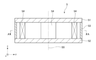
図1は、本発明のロボットを備えるロボットシステムの第1実施形態を示す側面図である。図2は、図1に示すロボットシステムのブロック図である。図3は、図1に示す力検出部の側面図である。図4は、図3中A-A線断面図である。図5は、図1に示すロボットの概略模式図である。
DESCRIPTION OF THE PREFERRED EMBODIMENTS The robot of the present invention will be described in detail below based on preferred embodiments shown in the accompanying drawings.
<First embodiment>
FIG. 1 is a side view showing a first embodiment of a robot system including a robot of the present invention. FIG. 2 is a block diagram of the robot system shown in FIG. 1. FIG. 3 is a side view of the force detection section shown in FIG. 1. FIG. 4 is a cross-sectional view taken along line AA in FIG. FIG. 5 is a schematic diagram of the robot shown in FIG. 1.
また、図1および図3~図7では、説明の便宜上、互いに直交する3軸として、x軸、y軸およびz軸を図示している。また、以下では、x軸に平行な方向を「x軸方向」とも言い、y軸に平行な方向を「y軸方向」とも言い、z軸に平行な方向を「z軸方向」とも言う。また、以下では、図示された各矢印の先端側を「+(プラス)」、基端側を「-(マイナス)」と言い、+x軸方向に平行な方向を「+x軸方向」とも言い、-x軸方向に平行な方向を「-x軸方向」とも言い、+y軸方向に平行な方向を「+y軸方向」とも言い、-y軸方向に平行な方向を「-y軸方向」とも言い、+z軸方向に平行な方向を「+z軸方向」とも言い、-z軸方向に平行な方向を「-z軸方向」とも言う。また、z軸回りの方向およびz軸に平行な軸回りの方向を「u軸方向」とも言う。 Further, in FIG. 1 and FIGS. 3 to 7, for convenience of explanation, an x-axis, a y-axis, and a z-axis are illustrated as three axes orthogonal to each other. Further, hereinafter, the direction parallel to the x-axis is also referred to as the "x-axis direction," the direction parallel to the y-axis is also referred to as the "y-axis direction," and the direction parallel to the z-axis is also referred to as the "z-axis direction." In addition, in the following, the tip side of each arrow shown in the figure is referred to as "+ (plus)", the proximal end side is referred to as "- (minus)", and the direction parallel to the +x-axis direction is also referred to as "+x-axis direction". The direction parallel to the -x-axis direction is also called the "-x-axis direction," the direction parallel to the +y-axis direction is also called the "+y-axis direction," and the direction parallel to the -y-axis direction is also called the "-y-axis direction." The direction parallel to the +z-axis direction is also called the "+z-axis direction," and the direction parallel to the -z-axis direction is also called the "-z-axis direction." Further, the direction around the z-axis and the direction around the axis parallel to the z-axis are also referred to as the "u-axis direction."
また、以下では、説明の便宜上、図1中の+z軸方向、すなわち、上側を「上」または「上方」、-z軸方向、すなわち、下側を「下」または「下方」とも言う。また、ロボットアーム20については、図1中の基台21側を「基端」、その反対側、すなわち、エンドエフェクター7側を「先端」と言う。また、図1中のz軸方向、すなわち、上下方向を「鉛直方向」とし、x軸方向およびy軸方向、すなわち、左右方向を「水平方向」とする。
In the following, for convenience of explanation, the +z-axis direction, ie, the upper side, in FIG. 1 will also be referred to as "upper" or "upper", and the -z-axis direction, ie, the lower side, will also be referred to as "lower" or "lower". Further, regarding the
図1および図2に示すロボットシステム100は、例えば、電子部品および電子機器等のワークの保持、搬送、組立ておよび検査等の作業で用いられる装置である。ロボットシステム100は、制御装置1と、ロボット2と、エンドエフェクター7と、を備えている。その他、ロボットシステム100は、表示装置41や、入力装置42等を備えている。
The
制御装置1は、ロボット2とは異なる位置、すなわち、ロボット2の外側に配置されている。また、図示の構成では、ロボット2と制御装置1とは、ケーブル200で電気的に接続(以下、単に「接続」とも言う)されているが、これに限定されずケーブル200を省略し、無線方式で通信を行うようになっていてもよい。すなわち、ロボット2と制御装置1とは、有線通信で接続されていてもよく、また、無線通信で接続されていてもよい。また、制御装置1は、ロボット2が有する基台21に内蔵されていてもよい。
The
ロボット2は、図示の構成では、水平多関節ロボット、すなわち、スカラロボットである。
In the illustrated configuration, the
図1に示すように、ロボット2は、基台21と、第1アーム22と、第2アーム23と、作業ヘッドである第3アーム24と、力検出部5と、を備えている。第1アーム22、第2アーム23および第3アーム24によりロボットアーム20が構成される。
As shown in FIG. 1, the
また、ロボット2は、第1アーム22を基台21に対して回転させる駆動ユニット25と、第2アーム23を第1アーム22に対して回転させる駆動ユニット26と、第3アーム24のシャフト241を第2アーム23に対して回転させるu駆動ユニット27と、シャフト241を第2アーム23に対してz軸方向に移動させるz駆動ユニット28と、角速度センサー29とを備えている。
The
このように、ロボット2は、ロボットアーム20を回転可能に支持する基台21を備え、ロボットアーム20は、第1アーム22と、基台21に対し第1アーム22よりも遠位側に位置する第2アーム23と、を含む。これにより、ロボットアーム20の可動域を大きくすることができる。
In this way, the
図1および図2に示すように、駆動ユニット25は、第1アーム22の筐体220内に内蔵されており、駆動力を発生するモーター251と、モーター251の駆動力を減速する減速機252と、モーター251または減速機252の回転軸の回転角度を検出する位置センサー253とを有している。
As shown in FIGS. 1 and 2, the
駆動ユニット26は、第2アーム23の筐体230に内蔵されており、駆動力を発生するモーター261と、モーター261の駆動力を減速する減速機262と、モーター261または減速機262の回転軸の回転角度を検出する位置センサー263とを有している。
The
u駆動ユニット27は、第2アーム23の筐体230に内蔵されており、駆動力を発生するモーター271と、モーター271の駆動力を減速する減速機272と、モーター271または減速機272の回転軸の回転角度を検出する位置センサー273とを有している。
The
z駆動ユニット28は、第2アーム23の筐体230に内蔵されており、駆動力を発生するモーター281と、モーター281の駆動力を減速する減速機282と、モーター281または減速機282の回転軸の回転角度を検出する位置センサー283とを有している。
The
モーター251、モーター261、モーター271およびモーター281としては、例えば、ACサーボモーター、DCサーボモーター等のサーボモーターを用いることができる。
As the
また、減速機252、減速機262、減速機272および減速機282としては、例えば、遊星ギア型の減速機、波動歯車装置等を用いることができる。また、位置センサー253、位置センサー263、位置センサー273および位置センサー283は、例えば、角度センサーとすることができる。
Further, as the
駆動ユニット25、駆動ユニット26、u駆動ユニット27およびz駆動ユニット28は、それぞれ、対応する図示しないモータードライバーに接続されており、モータードライバーを介して制御装置1のロボット制御部11により制御される。
The
また、角速度センサー29は、図1に示すように、第2アーム23に内蔵されている。このため、第2アーム23の角速度を検出することができる。この検出した角速度の情報に基づいて、制御装置1は、ロボット2の制御を行う。
Further, the
基台21は、例えば、図示しない床面にボルト等によって固定されている。基台21の上端部には第1アーム22が連結されている。第1アーム22は、基台21に対して鉛直方向に沿う第1軸O1回りに回転可能となっている。第1アーム22を回転させる駆動ユニット25が駆動すると、第1アーム22が基台21に対して第1軸O1回りに水平面内で回転する。また、位置センサー253により、基台21に対する第1アーム22の回転量が検出できるようになっている。
The
また、第1アーム22の先端部には、第2アーム23が連結されている。第2アーム23は、第1アーム22に対して鉛直方向に沿う第2軸O2回りに回転可能となっている。第1軸O1の軸方向と第2軸O2の軸方向とは同一である。すなわち、第2軸O2は、第1軸O1と平行である。第2アーム23を回転させる駆動ユニット26が駆動すると、第2アーム23が第1アーム22に対して第2軸O2回りに水平面内で回転する。また、位置センサー263により、第1アーム22に対する第2アーム23の駆動量、具体的には、回転量が検出できるようになっている。
Furthermore, a
また、第2アーム23の先端部には、第3アーム24が設置、支持されている。第3アーム24は、シャフト241を有している。シャフト241は、第2アーム23に対して、鉛直方向に沿う第3軸O3回りに回転可能であり、かつ、上下方向に移動可能となっている。このシャフト241は、ロボットアーム20の最も先端のアームである。
Further, a
シャフト241を回転させるu駆動ユニット27が駆動すると、シャフト241は、z軸回りに正逆回転、すなわち、回転する。また、位置センサー273により、第2アーム23に対するシャフト241の回転量が検出できるようになっている。
When the
また、シャフト241をz軸方向に移動させるz駆動ユニット28が駆動すると、シャフト241は、上下方向、すなわち、z軸方向に移動する。また、位置センサー283により、第2アーム23に対するシャフト241のz軸方向の移動量が検出できるようになっている。
Furthermore, when the
このように、ロボットアーム20は、第1アーム22と、第1アーム22の基台21と反対側に接続され、第1軸O1と平行な第2軸O2回りに回動する第2アーム23と、第2アーム23に支持され、第2軸O2とは異なる位置で、かつ、第2軸O2と平行な第3軸O3の軸方向に沿って移動する第3アーム24と、を有する。第1アーム22および第2アーム23により、xy平面での可動範囲を十分に確保することができるとともに、第3アーム24によりz軸方向にも作動することができる。
In this way, the
また、シャフト241の先端部には、各種のエンドエフェクターが着脱可能に連結される。エンドエフェクターとしては、特に限定されず、例えば、被搬送物を把持するもの、被加工物を加工するもの、検査に使用するもの等が挙げられる。本実施形態では、エンドエフェクター7が着脱可能に連結される。エンドエフェクター7については、後に詳述する。
Furthermore, various end effectors are detachably connected to the distal end of the
なお、エンドエフェクター7は、本実施形態では、ロボット2の構成要素になっていないが、エンドエフェクター7の一部または全部がロボット2の構成要素になっていてもよい。また、エンドエフェクター7は、本実施形態では、ロボットアーム20の構成要素になっていないが、エンドエフェクター7の一部または全部がロボットアーム20の構成要素になっていてもよい。
Although the end effector 7 is not a component of the
図1に示すように、エンドエフェクター7は、シャフト241に取り付けられた取り付け部71と、取り付け部71に設けられたモーター72と、モーター72の回転軸に、着脱可能に同心的に取り付けられたねじ用限界ゲージ3とを有している。このエンドエフェクター7は、シャフト241の先端部に着脱可能に連結される。
As shown in FIG. 1, the end effector 7 is removably attached concentrically to an
また、モーター72としては、特に限定されないが、例えば、ACサーボモーター、DCサーボモーター等のサーボモーター、ステッピングモーター等が用いられる。
Furthermore, the
また、エンドエフェクター7は、モーター72の回転軸の回転角度を検出する図示しない角度センサーを有しており、その位置センサーにより、モーター72の回転軸の回転角度が検出できるようになっている。
Furthermore, the end effector 7 has an angle sensor (not shown) that detects the rotation angle of the rotation shaft of the
このエンドエフェクター7では、モーター72の回転軸とねじ用限界ゲージ3との間に歯車やベルト等の動力伝達機構が介在している場合に比べて、バックラッシュによる回転精度の低下を抑制することができる。
This end effector 7 suppresses a decrease in rotation accuracy due to backlash compared to a case where a power transmission mechanism such as a gear or a belt is interposed between the rotating shaft of the
また、本実施形態では、エンドエフェクター7は、ロボットアーム20に対して着脱可能であるが、これに限定されず、例えば、エンドエフェクター7は、ロボットアーム20から離脱不能になっていてもよい。
Further, in the present embodiment, the end effector 7 is removable from the
次に、力検出部5について説明する。
図1および図3に示すように、力検出部5は、ロボット2に加わる力、すなわち、ロボットアーム20および基台21に加わる力を検出するものである。力検出部5は、基台21の下方、すなわち、-z軸側に設けられており、基台21を下方から支持している。このため、力検出部5には、ロボットアーム20および基台21の重量分の荷重がかかっている。
Next, the
As shown in FIGS. 1 and 3, the
また、図3に示すように、力検出部5は、第1プレート51と、第2プレート52と、第1プレート51と第2プレート52との間に配置された筒状部53と、複数、本実施形態では、4つの素子54とを有し、外形形状が円柱状をなす部材である。また、4つの素子54は、第1プレート51と、第2プレート52との間で挟持されている。また、素子54の数は、これに限定されず、3つ以下でもよく、5つ以上でもよい。
Further, as shown in FIG. 3, the
第1プレート51および第2プレート52は、円板状をなし、+z軸側からこの順で離間して配置されている。なお、第1プレート51および第2プレート52の平面視における形状は、円形に限定されず、いかなる形状であってもよい。
The
筒状部53は、本実施形態では、円筒状をなし、素子54を保護する機能を有する。
各素子54は、円形をなすように等間隔で配置されている。これにより、各素子54に加わる力が可及的に均一になり、正確に力を検出することができる。ここで、本明細書中では、各素子54が配置されている円Cの中心を通過し、かつ、z軸、すなわち、第1軸O1と平行な直線を中心線S5という。本実施形態において、力検出部5の中心とは、各素子54が配置されている円Cの中心である。しかし、各素子54が円形に配置されていない場合には、各素子54を頂点とする図形の幾何学的中心を力検出部5の中心という。
In this embodiment, the
Each
各素子54は、例えば、水晶等の圧電体で構成され、外力を受けると電荷を出力するものを用いることができる。また、制御装置1は、この電荷量に応じて、エンドエフェクター7が受けた外力に変換することができる。また、このような圧電体であると、設置する向きに応じて、外力を受けた際に電荷を発生させることができる向きを調整可能である。
Each
本実施形態では、各素子54は、図4に示すように、鉛直方向の成分の力Fzと、z軸回り、すなわち、u軸方向の力Fuとを検出することができる。すなわち、力検出部5は、第3軸O3の軸方向の力Fzを検出する。これにより、シャフト241をz軸方向に沿って移動させる作業をより正確に行うことができる。
In this embodiment, each
このようなロボット2には、ケーブル200を介して制御装置1が接続されている。
図2に示すように、制御装置1は、ロボット制御部11と、モーター制御部12(エンドエフェクター制御部)と、表示制御部13と、記憶部14と、受付部15と、を備えており、ロボット2、エンドエフェクター7のモーター72および表示装置41等、ロボットシステム100の各部の駆動をそれぞれ制御する。
A
As shown in FIG. 2, the
また、制御装置1は、ロボット制御部11と、モーター制御部12と、表示制御部13と、記憶部14と、受付部15との間で、それぞれ、通信可能に構成されている。すなわち、ロボット制御部11と、モーター制御部12と、表示制御部13と、記憶部14と、受付部15とは、互いに、有線または無線通信で接続されている。
Further, the
ロボット制御部11は、ロボット2の駆動、すなわち、ロボットアーム20等の駆動を制御する。ロボット制御部11は、OS等のプログラムがインストールされたコンピューターである。このロボット制御部11は、例えば、プロセッサとしてのCPUと、RAMと、プログラムが記憶されたROMとを有する。また、ロボット制御部11の機能は、例えば、CPUにより各種プログラムを実行することにより実現することができる。
The
モーター制御部12は、モーター72の駆動を制御する。モーター制御部12は、OS等のプログラムがインストールされたコンピューターである。このモーター制御部12は、例えば、プロセッサとしてのCPUと、RAMと、プログラムが記憶されたROMとを有する。また、モーター制御部12の機能は、例えば、CPUにより各種プログラムを実行することにより実現することができる。
The
表示制御部13は、表示装置41にウィンドウ等の各種の画面や文字等を表示させる機能を有している。すなわち、表示制御部13は、表示装置41の駆動を制御する。この表示制御部13の機能は、例えばGPU等により実現することができる。
The
記憶部14は、データやプログラム等の各種の情報を記憶する機能を有する。この記憶部14は、制御プログラム等を記憶する。記憶部14の機能は、ROM等のいわゆる外部記憶装置によって実現することができる。
The
受付部15は、入力装置42からの入力を受け付ける機能を有している。この受付部15の機能は、例えばインターフェース回路によって実現することができる。なお、例えばタッチパネルを用いる場合には、受付部15は、ユーザーの指のタッチパネルへの接触等を検知する入力検知部としての機能を有する。
The receiving
表示装置41は、例えば、液晶ディスプレイ、ELディスプレイ等で構成された図示しないモニターを備えており、例えば、ウィンドウ等の各種の画面等を含む各種の画像や文字等を表示する機能を有する。
The
入力装置42は、例えば、マウスやキーボード等で構成されている。したがって、ユーザーは、入力装置42を操作することで、制御装置1に対して各種の処理等の指示を行うことができる。
The
具体的には、ユーザーは、表示装置41に表示されるウィンドウ等の各種画面に対して入力装置42のマウスでクリックする操作や、入力装置42のキーボードで文字や数字等を入力する操作により、制御装置1に対する指示を行うことができる。
Specifically, the user clicks on various screens such as windows displayed on the
なお、本実施形態では、表示装置41および入力装置42の代わりに、表示装置41および入力装置42を兼ね備えた表示入力装置を設けてもよい。表示入力装置としては、例えば静電式タッチパネルや感圧式タッチパネル等のタッチパネルを用いることができる。また、入力装置42は、音声等の音を認識する構成であってもよい。
Note that in the present embodiment, a display input device having both the
このようなロボット2では、ロボットアーム20、基台21および力検出部5は、以下のような位置関係となっている。以下、第1軸O1と、中心線S2、基台21の中心線S21(第1中心線)、力検出部5の中心線S5(第2中心線)の位置関係について図5を用いて説明する。
In such a
第1軸O1は、前述したように、基台21に接続されている第1アーム22の回動軸である。また、第1軸O1は、z軸と平行である。
The first axis O1 is the rotation axis of the
中心線S2は、ロボット2の重心Gを通り、かつ、z軸、すなわち、第1軸O1と平行である。ロボット2の重心Gの位置は、ロボットアーム20の姿勢によって変位するため、中心線S2は、図5に示す領域A2内で変位する。領域A2は、x軸方向およびy軸方向に幅を持った空間である。
The center line S2 passes through the center of gravity G of the
以下では、ロボット2の重心Gは、ロボットアーム20がホームポジションに位置している場合の重心のこととして説明する。ホームポジションは、図1に示すように、第1アーム22および第2アーム23がy軸に沿って延びている状態で静止している状態のことを言う。換言すれば、第3軸O3が第1軸O1から最も離れた状態で、かつ、z軸方向から見たとき、図1に示す配管8が直線状に見える状態のことを言う。
In the following, the center of gravity G of the
基台21の中心線S21は、基台21の中心を通り、かつ、第1軸O1と平行な直線である。本実施形態において、基台21の中心とは、基台21をz軸方向から投影した投影形状における重心のことである。すなわち、基台21をz軸方向から投影した投影形状の幾何学的中心である。
The center line S21 of the
力検出部5の中心線S5は、前述したように、各素子54が配置されている円の中心を通過し、かつ、z軸、すなわち、第1軸O1と平行な直線を中心線S5という。
As described above, the center line S5 of the
本発明では、図5に示すように、中心線S5が中心線S21よりも第1軸O1側に位置している。すなわち、中心線S5は、中心線S21よりも第1軸O1側に近い。これにより、以下のような利点が得られる。 In the present invention, as shown in FIG. 5, the center line S5 is located closer to the first axis O1 than the center line S21. That is, the center line S5 is closer to the first axis O1 than the center line S21. This provides the following advantages:
ロボット2では、前述したように、ロボットアーム20は、基台21の中心線S21からずれた位置に接続されている。すなわち、基台21の中心線S21と第1軸O1とは、異なる位置に位置している。このため、ロボット2の重心Gは、基台21の中心線S21からずれた位置に位置している。よって、力検出部5には、ロボット2自身の重量により、図5中矢印で示すような慣性モーメントが生じる。その結果、慣性モーメントの影響により、力検出部5には、常に力が加わった状態となっている。
In the
力検出部5に常にかかっている力を力F1としたとき、第3アーム24に外力が加わっていない状態では、力検出部5は、力F1を検出している。そして、第3アーム24に図5中矢印方向の外力が加わると、この影響で力F2が力検出部5に加わる。このとき、力検出部5は、F1-F2の力である力F3を検出する。そして、制御装置1は、力検出部5が検出した力F3と力F1との差分に基づいて、すなわち、力検出部5が検出した力の変化量に基づいてロボットアーム20の制御を行う。
When the force that is always applied to the
力F1が力F2に比べて相対的に大きいと、前記変化量が相対的に小さくなる。このため、例えば、力F2が比較的小さい場合、力F2の正確な検出が難しくなるおそれがある。 When the force F1 is relatively larger than the force F2, the amount of change becomes relatively small. For this reason, for example, when the force F2 is relatively small, it may become difficult to accurately detect the force F2.
そこで、前述したように、本発明では、中心線S5が中心線S21よりも第1軸O1側に位置するように力検出部5を配置した。これにより、ロボット2の重心Gと力検出部5の中心線S5との距離を、従来よりも小さくすることができる。よって、図5中矢印で示すような慣性モーメントの影響で力検出部5に常に加わっている力F1を小さくすることができる。したがって、力検出部5が検出した力の変化量が力F1に対して相対的に大きくなり、力F2が比較的小さい場合であっても力F2を正確に検出することができる。以上より、本発明によれば、力検出部5の検出精度を高めることができる。
Therefore, as described above, in the present invention, the
また、本実施形態では、第1軸O1の軸方向から見て、第1軸O1と第2中心線である中心線S5とは、重なっている。すなわち、第1軸O1と中心線S5とは、一致している。これにより、第1アーム22が回動した際に生じる第1軸O1周りの慣性モーメントをさらに正確に検出することができる。
Moreover, in this embodiment, the first axis O1 and the center line S5, which is the second center line, overlap when viewed from the axial direction of the first axis O1. That is, the first axis O1 and the center line S5 coincide. Thereby, the moment of inertia around the first axis O1 that occurs when the
また、中心線S21と第3軸O3との離間距離をL1とし、中心線S21と中心線S5との離間距離をL2とし、中心線S5と中心線S2との離間距離をL3とし、中心線S21と第1軸O1との離間距離をL4とし、力検出部5から重心Gまでの高さをL5としたとき、L1~L5は、それぞれ、以下のような関係を満足するのが好ましい。
Further, the distance between the center line S21 and the third axis O3 is L1, the distance between the center line S21 and the center line S5 is L2, the distance between the center line S5 and the center line S2 is L3, and the center line When the distance between S21 and the first axis O1 is L4, and the height from the
ロボット2では、L2/L1は、0.01≦L2/L1≦0.8を満足するのが好ましく、0.05≦L2/L1≦0.6を満足するのがより好ましい。これにより、力検出部5の検出精度を効果的に高めることができる。L2/L1が小さすぎると、重心Gが力検出部5から離間する方向にシフトし、力検出部5に常にかかっている力F1が多くなりすぎる傾向を示し、検出精度が低下するおそれがある。一方、L2/L1が大きすぎると、基台21を力検出部5上にバランスよく配置するのが難しくなる。
In the
また、ロボット2では、L2/L3は、0.1≦L2/L3≦6.0を満足するのが好ましく、0.2≦L2/L3≦4.0を満足するのがより好ましい。これにより、力検出部5の検出精度を効果的に高めることができる。L2/L3が小さすぎると、重心Gが力検出部5から離間する方向にシフトし、力検出部5に常にかかっている力F1が多くなりすぎる傾向を示し、検出精度が低下するおそれがある。一方、L2/L3が大きすぎると、基台21を力検出部5上にバランスよく配置するのが難しくなる。
Further, in the
なお、本実施形態では、L2=L4であるため、L4/L3の好ましい数値範囲は、上記L2/L3の数値範囲と同じである。 In addition, in this embodiment, since L2=L4, the preferable numerical range of L4/L3 is the same as the numerical range of L2/L3 described above.
また、ロボット2では、L2/L5は、0.05≦L2/L5≦3.0を満足するのが好ましく、0.1≦L2/L5≦1.0を満足するのがより好ましい。これにより、力検出部5の検出精度を効果的に高めることができる。L2/L5が小さすぎると、力検出部5に常にかかっている力F1が多くなりすぎる傾向を示し、検出精度が低下するおそれがある。一方、L2/L5が大きすぎると、基台21を力検出部5上にバランスよく配置するのが難しくなる。
Further, in the
以上説明したように、ロボット2は、基台21と、基台21に接続され、第1軸O1回りに回動する第1アーム22を有するロボットアーム20と、基台21に設けられ、基台21またはロボットアーム20に作用する力を検出する力検出部5と、を備える。また、第1アーム22は、基台21の中心を通り、かつ、第1軸O1と平行な第1中心線である中心線S21からずれた位置で基台21に接続されている。そして、力検出部5の中心を通り、かつ、第1軸O1と平行な第2中心線である中心線S5は、第1中心線である中心線S21よりも第1軸O1に近い。これにより、ロボット2の重心Gと力検出部5の中心線S5との距離を、従来よりも小さくすることができる。よって、図5中矢印で示すような慣性モーメントの影響により力検出部5に常に加わっている力F1を小さくすることができる。したがって、力検出部5が検出した力の変化量が力F1に対して相対的に大きくなり、外力F2が比較的小さい場合であっても外力F2を正確に検出することができる。以上より、本発明によれば、力検出部5の検出精度を高めることができる。
As described above, the
<第2実施形態>
図6は、本発明のロボットの第2実施形態の概略模式図である。
<Second embodiment>
FIG. 6 is a schematic diagram of a second embodiment of the robot of the present invention.
以下、図6を参照して本発明のロボットの第2実施形態について説明するが、前述した実施形態との相違点を中心に説明し、同様の事項はその説明を省略する。 A second embodiment of the robot of the present invention will be described below with reference to FIG. 6, but the explanation will focus on the differences from the embodiments described above, and the explanation of similar matters will be omitted.
図6に示すように、本実施形態では、x軸方向から見たとき、中心線S5は、第1軸O1と中心線S21との間に位置している。すなわち、第1軸O1および第1中心線である中心線S21を含む平面の平面視において、第2中心線である中心線S5は、第1軸O1と第1中心線である中心線S21との間に位置している。これにより、本発明の効果を得ることができるとともに、第1実施形態よりも力検出部5を基台21の中央部に配置させることができ、力検出部5が基台21をより安定的に支持することができる。
As shown in FIG. 6, in this embodiment, when viewed from the x-axis direction, the center line S5 is located between the first axis O1 and the center line S21. That is, in a plan view of a plane including the first axis O1 and the center line S21, which is the first center line, the center line S5, which is the second center line, is the same as the first axis O1 and the center line S21, which is the first center line. It is located between. As a result, the effects of the present invention can be obtained, and the
なお、本実施形態では、第1軸O1、中心線S5および中心線S21は、同一平面上に位置しているが、これに限定されず、これらは、同一平面上に位置していなくてもよい。 Note that in this embodiment, the first axis O1, the center line S5, and the center line S21 are located on the same plane, but the present invention is not limited to this, and they may not be located on the same plane. good.
<第3実施形態>
図7は、本発明のロボットの第3実施形態の概略模式図である。
<Third embodiment>
FIG. 7 is a schematic diagram of a third embodiment of the robot of the present invention.
以下、図7を参照して本発明のロボットの第3実施形態について説明するが、前述した実施形態との相違点を中心に説明し、同様の事項はその説明を省略する。 A third embodiment of the robot of the present invention will be described below with reference to FIG. 7, but the explanation will focus on the differences from the embodiments described above, and the explanation of similar matters will be omitted.
図7に示すように、本実施形態では、x軸方向から見たとき、中心線S5は、中心線S2と、第1軸O1との間に位置している。すなわち、第1軸O1および第1中心線である中心線S21を含む平面の平面視において、第2中心線である中心線S5は、ロボット2の重心Gを通り、かつ、第1軸O1と平行な直線である中心線S2と、第1軸O1との間に位置している。これにより、本発明の効果を得ることができるとともに、前記各実施形態よりも中心線S5が中心線S2に近い分、図7中矢印で示すような慣性モーメントの影響により力検出部5に常に加わっている力F1を小さくすることができる。
As shown in FIG. 7, in this embodiment, when viewed from the x-axis direction, the center line S5 is located between the center line S2 and the first axis O1. That is, in a plan view of a plane including the first axis O1 and the center line S21, which is the first center line, the center line S5, which is the second center line, passes through the center of gravity G of the
なお、本実施形態では、第1軸O1、中心線S5および中心線S21は、同一平面上に位置しているが、これに限定されず、これらは、同一平面上に位置していなくてもよい。 Note that in this embodiment, the first axis O1, the center line S5, and the center line S21 are located on the same plane, but the present invention is not limited to this, and they may not be located on the same plane. good.
以上、本発明のロボットを図示の実施形態に基づいて説明したが、本発明は、これに限定されるものではなく、各部の構成は、同様の機能を有する任意の構成のものに置換することができる。また、他の任意の構成物が付加されていてもよい。また、各実施形態の特徴を組み合わせてもよい。 Although the robot of the present invention has been described above based on the illustrated embodiment, the present invention is not limited to this, and the configuration of each part may be replaced with any configuration having a similar function. I can do it. Further, other arbitrary components may be added. Moreover, the features of each embodiment may be combined.
また、前記実施形態では、ロボットアームの回転軸の数は、3つであるが、本発明では、これに限定されず、ロボットアームの回転軸の数は、例えば、2つ、または、4つ以上でもよい。すなわち、前記実施形態では、アームの数は、3つであるが、本発明では、これに限定されず、アームの数は、例えば、2つ、または、4つ以上でもよい。 Further, in the embodiment, the number of rotation axes of the robot arm is three, but the present invention is not limited to this, and the number of rotation axes of the robot arm is, for example, two or four. The above is fine. That is, in the embodiment, the number of arms is three, but the present invention is not limited to this, and the number of arms may be, for example, two or four or more.
1…制御装置、2…ロボット、3…ねじ用限界ゲージ、5…力検出部、7…エンドエフェクター、8…配管、11…ロボット制御部、12…モーター制御部、13…表示制御部、14…記憶部、15…受付部、20…ロボットアーム、21…基台、22…第1アーム、23…第2アーム、24…第3アーム、25…駆動ユニット、26…駆動ユニット、27…u駆動ユニット、28…z駆動ユニット、29…角速度センサー、41…表示装置、42…入力装置、51…第1プレート、52…第2プレート、53…筒状部、54…素子、71…取り付け部、72…モーター、100…ロボットシステム、200…ケーブル、220…筐体、230…筐体、241…シャフト、251…モーター、252…減速機、253…位置センサー、261…モーター、262…減速機、263…位置センサー、271…モーター、272…減速機、273…位置センサー、281…モーター、282…減速機、283…位置センサー、A2…領域、C…円、Fu…力、Fz…力、G…重心、O1…第1軸、O2…第2軸、O3…第3軸、S2…中心線、S21…中心線、S5…中心線
DESCRIPTION OF
Claims (6)
前記基台に接続され、第1軸回りに回動する第1アームを有するロボットアームと、
前記基台に設けられ、前記基台または前記ロボットアームに作用する力を検出する力検出部と、を備え、
前記第1アームは、前記基台の中心を通り、かつ、前記第1軸と平行な第1中心線からずれた位置で前記基台に接続されており、
前記第1軸および前記第1中心線を含む平面の平面視において、
前記力検出部の中心を通り、かつ、前記第1軸と平行な第2中心線は、当該ロボットの重心を通り、かつ、前記第1軸と平行な直線と、前記第1軸と、の間に位置していることを特徴とするロボット。 The base and
a robot arm connected to the base and having a first arm that rotates around a first axis;
a force detection unit provided on the base and detecting a force acting on the base or the robot arm;
The first arm passes through the center of the base and is connected to the base at a position offset from a first center line parallel to the first axis ,
In a plan view of a plane including the first axis and the first center line,
A second center line passing through the center of the force detection unit and parallel to the first axis is connected to a straight line passing through the center of gravity of the robot and parallel to the first axis, and the first axis. A robot characterized by being located between .
前記基台に接続され、第1軸回りに回動する第1アームを有するロボットアームと、
前記基台に設けられ、前記基台または前記ロボットアームに作用する力を検出する力検出部と、を備え、
前記第1アームは、前記基台の中心を通り、かつ、前記第1軸と平行な第1中心線からずれた位置で前記基台に接続されており、
前記第1軸および前記第1中心線を含む平面の平面視において、
前記力検出部の中心を通り、かつ、前記第1軸と平行な第2中心線は、前記第1軸と、前記第1中心線と、の間に位置していることを特徴とするロボット。 The base and
a robot arm connected to the base and having a first arm that rotates around a first axis;
a force detection unit provided on the base and detecting a force acting on the base or the robot arm;
The first arm passes through the center of the base and is connected to the base at a position offset from a first center line parallel to the first axis,
In a plan view of a plane including the first axis and the first center line,
A robot characterized in that a second center line passing through the center of the force detection unit and parallel to the first axis is located between the first axis and the first center line. .
前記基台に接続され、第1軸回りに回動する第1アームを有するロボットアームと、 a robot arm connected to the base and having a first arm that rotates around a first axis;
前記基台に設けられ、前記基台または前記ロボットアームに作用する力を検出する力検出部と、を備え、 a force detection unit provided on the base and detecting a force acting on the base or the robot arm;
前記第1アームは、前記基台の中心を通り、かつ、前記第1軸と平行な第1中心線からずれた位置で前記基台に接続されており、 The first arm passes through the center of the base and is connected to the base at a position offset from a first center line parallel to the first axis,
前記力検出部の中心を通り、かつ、前記第1軸と平行な第2中心線は、前記第1中心線よりも前記第1軸に近く、 A second center line passing through the center of the force detection unit and parallel to the first axis is closer to the first axis than the first center line,
前記第1軸および前記第1中心線を含む平面の平面視において、 In a plan view of a plane including the first axis and the first center line,
前記第2中心線は、当該ロボットの重心を通り、かつ、前記第1軸と平行な直線と、前記第1軸と、の間に位置していることを特徴とするロボット。 The robot, wherein the second center line is located between the first axis and a straight line passing through the center of gravity of the robot and parallel to the first axis.
前記基台に接続され、第1軸回りに回動する第1アームを有するロボットアームと、 a robot arm connected to the base and having a first arm that rotates around a first axis;
前記基台に設けられ、前記基台または前記ロボットアームに作用する力を検出する力検出部と、を備え、 a force detection unit provided on the base and detecting a force acting on the base or the robot arm;
前記第1アームは、前記基台の中心を通り、かつ、前記第1軸と平行な第1中心線からずれた位置で前記基台に接続されており、 The first arm passes through the center of the base and is connected to the base at a position offset from a first center line parallel to the first axis,
前記力検出部の中心を通り、かつ、前記第1軸と平行な第2中心線は、前記第1中心線よりも前記第1軸に近く、 A second center line passing through the center of the force detection unit and parallel to the first axis is closer to the first axis than the first center line,
前記第1軸および前記第1中心線を含む平面の平面視において、 In a plan view of a plane including the first axis and the first center line,
前記第2中心線は、前記第1軸と前記第1中心線との間に位置していることを特徴とするロボット。 The robot, wherein the second centerline is located between the first axis and the first centerline.
Priority Applications (3)
| Application Number | Priority Date | Filing Date | Title |
|---|---|---|---|
| JP2019119690A JP7375345B2 (en) | 2019-06-27 | 2019-06-27 | robot |
| CN202010578579.5A CN112140105B (en) | 2019-06-27 | 2020-06-23 | robot |
| US16/912,744 US11458616B2 (en) | 2019-06-27 | 2020-06-26 | Robot |
Applications Claiming Priority (1)
| Application Number | Priority Date | Filing Date | Title |
|---|---|---|---|
| JP2019119690A JP7375345B2 (en) | 2019-06-27 | 2019-06-27 | robot |
Publications (3)
| Publication Number | Publication Date |
|---|---|
| JP2021003783A JP2021003783A (en) | 2021-01-14 |
| JP2021003783A5 JP2021003783A5 (en) | 2022-06-01 |
| JP7375345B2 true JP7375345B2 (en) | 2023-11-08 |
Family
ID=73887455
Family Applications (1)
| Application Number | Title | Priority Date | Filing Date |
|---|---|---|---|
| JP2019119690A Active JP7375345B2 (en) | 2019-06-27 | 2019-06-27 | robot |
Country Status (3)
| Country | Link |
|---|---|
| US (1) | US11458616B2 (en) |
| JP (1) | JP7375345B2 (en) |
| CN (1) | CN112140105B (en) |
Families Citing this family (1)
| Publication number | Priority date | Publication date | Assignee | Title |
|---|---|---|---|---|
| JP7451889B2 (en) * | 2019-06-27 | 2024-03-19 | セイコーエプソン株式会社 | robot |
Citations (5)
| Publication number | Priority date | Publication date | Assignee | Title |
|---|---|---|---|---|
| JP2006021287A (en) | 2004-07-09 | 2006-01-26 | Univ Waseda | Device for detecting contact force of robot |
| JP3204177U (en) | 2016-03-01 | 2016-05-19 | 株式会社レプトリノ | Force detection system |
| JP2018094639A (en) | 2016-12-08 | 2018-06-21 | ファナック株式会社 | Robot system |
| JP2018120306A (en) | 2017-01-23 | 2018-08-02 | セイコーエプソン株式会社 | Encoder, robot and printer |
| JP2019042906A (en) | 2017-09-07 | 2019-03-22 | 株式会社不二越 | Device for doubly checking external contact of robot |
Family Cites Families (8)
| Publication number | Priority date | Publication date | Assignee | Title |
|---|---|---|---|---|
| JP6008112B2 (en) * | 2012-10-23 | 2016-10-19 | セイコーエプソン株式会社 | Horizontal articulated robot |
| JP6193816B2 (en) * | 2014-06-20 | 2017-09-06 | ファナック株式会社 | Articulated robot with arm retracting function |
| JP6300693B2 (en) * | 2014-09-30 | 2018-03-28 | セイコーエプソン株式会社 | robot |
| JP6342971B2 (en) | 2016-11-14 | 2018-06-13 | ファナック株式会社 | Force detection device and robot |
| JP6862794B2 (en) * | 2016-11-24 | 2021-04-21 | セイコーエプソン株式会社 | Force detection sensor, force sensor, torque sensor and robot |
| JP6988152B2 (en) * | 2017-05-08 | 2022-01-05 | セイコーエプソン株式会社 | robot |
| JP2019098407A (en) * | 2017-11-28 | 2019-06-24 | ファナック株式会社 | robot |
| US11872698B2 (en) * | 2018-02-13 | 2024-01-16 | Canon Kabushiki Kaisha | Controller of robot and control method |
-
2019
- 2019-06-27 JP JP2019119690A patent/JP7375345B2/en active Active
-
2020
- 2020-06-23 CN CN202010578579.5A patent/CN112140105B/en active Active
- 2020-06-26 US US16/912,744 patent/US11458616B2/en active Active
Patent Citations (5)
| Publication number | Priority date | Publication date | Assignee | Title |
|---|---|---|---|---|
| JP2006021287A (en) | 2004-07-09 | 2006-01-26 | Univ Waseda | Device for detecting contact force of robot |
| JP3204177U (en) | 2016-03-01 | 2016-05-19 | 株式会社レプトリノ | Force detection system |
| JP2018094639A (en) | 2016-12-08 | 2018-06-21 | ファナック株式会社 | Robot system |
| JP2018120306A (en) | 2017-01-23 | 2018-08-02 | セイコーエプソン株式会社 | Encoder, robot and printer |
| JP2019042906A (en) | 2017-09-07 | 2019-03-22 | 株式会社不二越 | Device for doubly checking external contact of robot |
Also Published As
| Publication number | Publication date |
|---|---|
| US11458616B2 (en) | 2022-10-04 |
| US20200406451A1 (en) | 2020-12-31 |
| JP2021003783A (en) | 2021-01-14 |
| CN112140105A (en) | 2020-12-29 |
| CN112140105B (en) | 2023-11-24 |
Similar Documents
| Publication | Publication Date | Title |
|---|---|---|
| JP6111562B2 (en) | robot | |
| US20170312922A1 (en) | Vibration measurement method for moving part, vibration measurement method for robot, and control device | |
| CN110539301B (en) | Control device, robot, and robot system | |
| US9950427B2 (en) | Robot, control apparatus, and robot system | |
| US11420326B2 (en) | Horizontal articulated robot | |
| JP2018118365A (en) | Control device and robot system | |
| JP2017056521A (en) | Robot, control device and robot system | |
| US20180154520A1 (en) | Control device, robot, and robot system | |
| US20170120444A1 (en) | Robot, control apparatus, and robot system | |
| JP7375345B2 (en) | robot | |
| JP2006312207A (en) | Force sense controller device and its controlling method | |
| US11458625B2 (en) | Horizontal articulated robot and robot system | |
| CN112643683B (en) | Teaching method | |
| JP7238489B2 (en) | Horizontal articulated robot | |
| JP7392326B2 (en) | robot | |
| JP7415447B2 (en) | robot system | |
| JP6036476B2 (en) | robot | |
| US20210178577A1 (en) | Control method and robot system | |
| JP2023182991A (en) | Robot and robot system |
Legal Events
| Date | Code | Title | Description |
|---|---|---|---|
| RD07 | Notification of extinguishment of power of attorney |
Free format text: JAPANESE INTERMEDIATE CODE: A7427 Effective date: 20200811 |
|
| RD04 | Notification of resignation of power of attorney |
Free format text: JAPANESE INTERMEDIATE CODE: A7424 Effective date: 20210916 |
|
| RD03 | Notification of appointment of power of attorney |
Free format text: JAPANESE INTERMEDIATE CODE: A7423 Effective date: 20211102 |
|
| A521 | Request for written amendment filed |
Free format text: JAPANESE INTERMEDIATE CODE: A523 Effective date: 20220524 |
|
| A621 | Written request for application examination |
Free format text: JAPANESE INTERMEDIATE CODE: A621 Effective date: 20220524 |
|
| A131 | Notification of reasons for refusal |
Free format text: JAPANESE INTERMEDIATE CODE: A131 Effective date: 20230516 |
|
| A521 | Request for written amendment filed |
Free format text: JAPANESE INTERMEDIATE CODE: A523 Effective date: 20230713 |
|
| TRDD | Decision of grant or rejection written | ||
| A01 | Written decision to grant a patent or to grant a registration (utility model) |
Free format text: JAPANESE INTERMEDIATE CODE: A01 Effective date: 20230926 |
|
| A61 | First payment of annual fees (during grant procedure) |
Free format text: JAPANESE INTERMEDIATE CODE: A61 Effective date: 20231009 |
|
| R150 | Certificate of patent or registration of utility model |
Ref document number: 7375345 Country of ref document: JP Free format text: JAPANESE INTERMEDIATE CODE: R150 |