EP0806643A2 - Device for measuring the force and/or torque - Google Patents
Device for measuring the force and/or torque Download PDFInfo
- Publication number
- EP0806643A2 EP0806643A2 EP97810192A EP97810192A EP0806643A2 EP 0806643 A2 EP0806643 A2 EP 0806643A2 EP 97810192 A EP97810192 A EP 97810192A EP 97810192 A EP97810192 A EP 97810192A EP 0806643 A2 EP0806643 A2 EP 0806643A2
- Authority
- EP
- European Patent Office
- Prior art keywords
- force
- platform
- measuring
- measuring arrangement
- cells
- Prior art date
- Legal status (The legal status is an assumption and is not a legal conclusion. Google has not performed a legal analysis and makes no representation as to the accuracy of the status listed.)
- Granted
Links
- 238000011156 evaluation Methods 0.000 claims abstract description 9
- 230000035945 sensitivity Effects 0.000 claims abstract description 8
- 230000036316 preload Effects 0.000 claims description 18
- 238000005452 bending Methods 0.000 claims description 4
- 230000007935 neutral effect Effects 0.000 claims description 4
- 238000005259 measurement Methods 0.000 abstract description 14
- 238000003754 machining Methods 0.000 description 7
- 230000001419 dependent effect Effects 0.000 description 2
- 238000005553 drilling Methods 0.000 description 2
- 230000000694 effects Effects 0.000 description 2
- 239000013078 crystal Substances 0.000 description 1
- 238000010438 heat treatment Methods 0.000 description 1
- 239000002655 kraft paper Substances 0.000 description 1
- 238000006386 neutralization reaction Methods 0.000 description 1
- 239000010453 quartz Substances 0.000 description 1
- 230000008054 signal transmission Effects 0.000 description 1
- VYPSYNLAJGMNEJ-UHFFFAOYSA-N silicon dioxide Inorganic materials O=[Si]=O VYPSYNLAJGMNEJ-UHFFFAOYSA-N 0.000 description 1
Images


Classifications
-
- G—PHYSICS
- G01—MEASURING; TESTING
- G01L—MEASURING FORCE, STRESS, TORQUE, WORK, MECHANICAL POWER, MECHANICAL EFFICIENCY, OR FLUID PRESSURE
- G01L5/00—Apparatus for, or methods of, measuring force, work, mechanical power, or torque, specially adapted for specific purposes
- G01L5/16—Apparatus for, or methods of, measuring force, work, mechanical power, or torque, specially adapted for specific purposes for measuring several components of force
- G01L5/167—Apparatus for, or methods of, measuring force, work, mechanical power, or torque, specially adapted for specific purposes for measuring several components of force using piezoelectric means
Definitions
- the invention relates to a force and / or torque measuring arrangement with a plurality of multi-component force measuring cells equipped with piezoelectric sensors in connection with platforms for force and / or moment introduction and with amplifiers and evaluation units, the force measuring cells each consisting of thrust and tension / pressure sensitive sensor disks .
- a measuring arrangement for the measurement of forces and torques is known, in which several multi-component load cells are arranged under prestress between a base plate and a cover plate.
- the preload for the measuring cells which contain both thrust and tension / pressure-sensitive sensor disks, is generated by a preload screw that penetrates the measuring cell and is screwed into the base plate from the cover plate.
- the orientation of the sensors in the multi-component measuring cells which consist of single crystals, for example quartz, or polycrystalline piezoceramic, is such that the tensile / pressure sensitivity of the sensors is directed perpendicular to the surface of the cover plate (z direction), which acts as a mounting plate for machining workpieces.
- the stated object is achieved in that the load cells, viewed in the direction of the tensile / pressure sensitivity of the sensors, are arranged on both end faces of the platform, and that paired, tensile / pressure-sensitive sensor disks are also assigned to one another by a common preload screw that is freely stretchable in the platform are interspersed and prestressed, and that finally the mutually assigned, tension / pressure-sensitive sensor disks at the ends of the platform are opposite and at least approximately equally polarized.
- a temperature change which causes a change in length via the force introduction plate located between the sensors and acts on the sensors assigned to one another via this change in length, produces opposite signs as a result of the opposite orientation of the sensor disks in these charges, which therefore "neutralize” each other in the measurement signal.
- the charges of both sensors add up to the required force measurement signal.
- Measurement signals caused by temperature changes are formed in an analogous manner when the measuring device is heated on one side.
- the heat is conducted into the continuous preload screw and in turn causes a "neutralization" of the temperature-dependent measurement signals in the multi-component load cells.
- the platform is a rigid mounting plate for the workpieces to be machined, in which the load cells are arranged perpendicular to the mounting surface for the workpieces.
- the platform can be arranged between the measuring points and two outer mounting blocks, which in turn are used to mount the measuring arrangement, this mounting being carried out with the aid of clamping screws arranged near the sensors.
- the arrangement of the common pretensioning screw in the axis of the platform, which is neutral with respect to bending, can additionally minimize or avoid false signals due to bending of the platform.
- the signal routing of several measuring cells is simplified if the signal lines for the measuring signals of the individual measuring cells are brought together in a collecting channel and led outwards via a collecting plug, from where they are led as a cable connection to the amplifiers and the evaluation units.
- FIG. 1 which represents the state of the art, four multicomponent load cells A are arranged between a base plate 1 and a cover plate 2 under prestress.
- the preload is generated by preload screws 3 which pass through the cover plate 2 and the measuring cells A and are screwed into the base plate 1.
- a workpiece 4 is mounted on the cover plate 2 and is machined by a tool 5, which is only indicated.
- a single force measuring cell A contains a plurality of piezoelectric sensor disks 6, at least one of which is sensitive to tension / pressure in the z-direction of a right-angled coordinate system and at least one is sensitive to thrust in the x and y directions.
- the measuring cell A contains a bore 7.
- the signal line connections on the measuring cell A for the signal components in the x, y and z directions are designated x, y, z.
- the two coordinate systems for the measuring arrangement and for the measuring cell are oriented identically, as a comparison of FIGS. 1 and 2 shows .
- the measuring arrangement is loaded with a temperature increase ⁇ T (FIG. 1) on the one hand and with a force F on the other hand, of which only the component Fz in the z direction is shown in FIG. 2.
- ⁇ T temperature increase
- F force on the other hand
- ⁇ l expansion
- the cover plate 2 is replaced by a T-shaped mounting platform 8 which is mounted in a U-shaped stand 9.
- the load cells A and B are no longer arranged horizontally, but between the vertical ones U legs of the stand 9 and the trunk of the T platform 8 clamped vertically.
- the pre-tensioning of the measuring cells A and B takes place by means of a single pre-tensioning screw 10 passing through the trunk of the platform 8 and extending through the platform 8 without any friction.
- the sensor disks 6 of the measuring cells A and B are arranged and oriented such that, on the one hand, the z direction of the sensor disks 6, which is determined by the direction of their tension / pressure sensitivity, runs in the direction of the preload screw 10 and, on the other hand, the tension / Pressure sensitivity for measuring cell A is opposite to that of measuring cell B.
- the coordinate system of the measuring cells is consequently rotated by 90 ° with respect to that of the measuring arrangement.
- a charge -Q z is generated as a function of the force 1/2 F T
- the charge + Q z is due to the opposite orientation / pressure sensitive sensor disc the charge + Q z, also as a function of 1/2 F T , occurs.
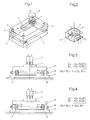
- FIG. 5 and 6 show in spatial representation, or in section, the structure of a dynamometer for the machining of workpieces.
- This dynamometer is characterized by an extremely low overall height H (Fig. 6).
- a very rigid mounting plate 11 serves on the one hand for receiving the workpiece 4 (FIG. 6) machined by the rotating, cutting tool 5 (FIG. 6) and on the other hand at the same time as a force introduction plate for the measuring cells A and B.
- These are in each case clamped in a vertical position between the end faces of the plate 11 and mounting blocks 12, the pretensioning in turn being applied by the continuous pretensioning screw 10.
- the pretensioning screws 10 are arranged in the axis 13 (FIG. 6) of the plate 11 which is neutral with respect to bending.
- the mounting blocks 12 have a number of bores 14 for the passage of clamping screws, not shown, with which the measuring arrangement itself can be mounted, for example, in a machine tool.
- the bores 14 are located as close as possible to the measuring cells A and B. As a result, the rigidity of the mounted measuring arrangement is as great as possible, which results in a high natural frequency of the system.
- FIG. 5 as shown in FIGS. 1 and 2, the two different coordinate systems are shown, namely the left above the mounting plate 11 relating to the entire measuring arrangement and the measuring cell-related in the left front or rear measuring cell A or B.
- the z-axes of the measuring cell-related coordinate system are directed towards one another with opposite signs.
- the signal lines 15 (FIG. 5) of the individual measuring cells are led to a common plug 16, from which they arrive as cables 17 to amplifiers and evaluation units, not shown.
- amplifiers and evaluation units in the mounting plate 11 and / or in one of the mounting blocks 12 in cavities 18 and 19, which are indicated by dashed lines in FIG. 5.
- the already amplified and processed signals are then passed on from these cavities 18 and 19, thereby increasing operational reliability the arrangement is increased.
- the exemplary embodiment according to FIG. 7 shows a rotating measuring arrangement which is mounted on the wheel hub of a vehicle for measuring the wheel forces and moments.
- a rim 21 of a motor vehicle wheel is connected via an intermediate ring 20 to a disk plate 22 designed as a force introduction platform.
- the measuring cells A and B rest on both sides of this disk plate 22, which in turn are clamped between the disk plate 22 and two force deflection plates 23 and 24 by means of the continuous preload screw 10.
- their sensor disks are oriented in such a way that their tension / pressure sensitivity runs in the direction of the preload screw 10, and that the measurement signals are caused by increases in temperature caused by the expansion of the disk plate 22 and the preload screw 10 in the measuring cells A and B cause charges, cancel each other out, while charges generated by unidirectional forces of both measuring cells A and B add to the desired measurement signal.
- the force deflection plates 23 and 24 are connected to a likewise disk-shaped holder 25.
Abstract
Description
Die Erfindung betrifft eine Kraft- und/oder Momentmessanordnung mit mehreren mit piezoelektrischen Sensoren ausgerüsteten Mehrkomponenten-Kraftmesszellen in Verbindung mit Plattformen für die Kraft- und/oder Momenteinleitung und mit Verstärkern und Auswerteeinheiten, wobei die Kraftmesszellen jeweils aus schub- und zug/druckempfindlichen Sensorscheiben bestehen.The invention relates to a force and / or torque measuring arrangement with a plurality of multi-component force measuring cells equipped with piezoelectric sensors in connection with platforms for force and / or moment introduction and with amplifiers and evaluation units, the force measuring cells each consisting of thrust and tension / pressure sensitive sensor disks .
Aus der DE-C-1952522 ist eine Messanordnung für die Messung von Kräften und Drehmomenten bekannt, bei der zwischen einer Grund-und einer Deckplatte mehrere Mehrkomponenten-Kraftmesszellen unter Vorspannung angeordnet sind. Die Vorspannung für die Messzellen, die sowohl schub- als auch zug/druckempfindliche Sensorscheiben enthalten, wird dabei jeweils durch eine die Messzelle durchsetzende Vorspannschraube erzeugt, die von der Deckplatte her in die Grundplatte eingeschraubt wird. Die Orientierung der aus Einkristallen, beispielsweise aus Quarz, oder aus polykristalliner Piezokeramik bestehenden Sensoren in den Mehrkomponenten-Messzellen ist dabei so, dass die Zug/Druckempfindlichkeit der Sensoren senkrecht zur Oberfläche der Deckplatte (z-Richtung) gerichtet ist, die als Montageplatte für zu bearbeitende Werkstücke dient.From DE-C-1952522 a measuring arrangement for the measurement of forces and torques is known, in which several multi-component load cells are arranged under prestress between a base plate and a cover plate. The preload for the measuring cells, which contain both thrust and tension / pressure-sensitive sensor disks, is generated by a preload screw that penetrates the measuring cell and is screwed into the base plate from the cover plate. The orientation of the sensors in the multi-component measuring cells, which consist of single crystals, for example quartz, or polycrystalline piezoceramic, is such that the tensile / pressure sensitivity of the sensors is directed perpendicular to the surface of the cover plate (z direction), which acts as a mounting plate for machining workpieces.
Es hat sich nun gezeigt, dass bei Temperaturschwankungen in der Messanordnung, beispielsweise durch eine infolge der Werkstückbearbeitung auftretende Erwärmung, die Kraftmessungen für die Druckkraftkomponente verfälscht werden, weil dadurch eine unterschiedliche Längenänderung von Deckplatte und Vorspannschrauben und somit eine Änderung der Vorspannung bewirkt wird.It has now been shown that in the event of temperature fluctuations in the measuring arrangement, for example as a result of heating occurring as a result of the machining of the workpiece, the force measurements for the compressive force component are falsified because this causes a different change in length of the cover plate and preload screws and thus a change in the preload.
Besonders bei Fein- und Feinstbearbeitungen von Werkstücken sind diese von Temperaturänderungen hervorgerufenen Fehler der Messwerte für die Druckkraftkomponente nicht tolerierbar. Es ist daher die Aufgabe der Erfindung, eine Kraftmessanordnung zu schaffen, bei der die von Temperaturänderungen hervorgerufenen Messfehler möglichst weitgehend kompensiert werden. Selbstverständlich ist jedoch die Anwendung der neuen, temperaturkompensierten Messanordnung nicht auf die Kraft- und Momentmessung bei der Bearbeitung von Werkstücken beschränkt.Particularly in the case of fine and ultra-fine machining of workpieces, these errors in the measured values caused by temperature changes for the pressure force component cannot be tolerated. It is therefore the object of the invention to create a force measuring arrangement in which the measurement errors caused by temperature changes are largely compensated for. Of course, however, the application of the new, temperature-compensated measuring arrangement to the force and torque measurement during processing is not limited by workpieces.
Die genannte Aufgabe wird erfindungsgemäss dadurch gelöst, dass die Kraftmesszellen, in Richtung der Zug/Druckempfindlichkeit der Sensoren gesehen, an beiden Endflächen der Plattform angeordnet sind, dass ferner paarweise einander zugeordnete, zug/druckempfindliche Sensorscheiben von einer gemeinsamen, in der Plattform frei dehnbaren Vorspannschraube durchsetzt und vorgespannt sind, und dass schliesslich die einander zugeordneten, zug/druckempfindlichen Sensorscheiben an den Enden der Plattform entgegengesetzt und mindestens annähernd gleich stark polarisiert sind.According to the invention, the stated object is achieved in that the load cells, viewed in the direction of the tensile / pressure sensitivity of the sensors, are arranged on both end faces of the platform, and that paired, tensile / pressure-sensitive sensor disks are also assigned to one another by a common preload screw that is freely stretchable in the platform are interspersed and prestressed, and that finally the mutually assigned, tension / pressure-sensitive sensor disks at the ends of the platform are opposite and at least approximately equally polarized.
Eine Temperaturänderung, die über die zwischen den Sensoren gelegene Krafteinleitplatte eine Längenänderung verursacht und über diese Längenänderung auf die einander zugeordneten Sensoren einwirkt, erzeugt infolge der entgegengesetzten Orientierung der Sensorscheiben in diesen Ladungen entgegengesetzten Vorzeichens, die sich daher in dem Messsignal gegenseitig "neutralisieren". Für eine in einer Richtung wirkende Kraftkomponente addieren sich die Ladungen beider Sensoren dagegen zu dem geforderten Kraftmesssignal.A temperature change, which causes a change in length via the force introduction plate located between the sensors and acts on the sensors assigned to one another via this change in length, produces opposite signs as a result of the opposite orientation of the sensor disks in these charges, which therefore "neutralize" each other in the measurement signal. In contrast, for a force component acting in one direction, the charges of both sensors add up to the required force measurement signal.
In analoger Weise werden durch Temperaturänderungen bewirkte Mess-signale gebildet, wenn die Messeinrichtung einseitig erwärmt wird. Die Wärme wird in die durchgehende Vorspannschraube geleitet und verursacht so wiederum eine "Neutralisierung" der temperaturabhängigen Messsignale in den Mehrkomponentenkraftmesszellen.Measurement signals caused by temperature changes are formed in an analogous manner when the measuring device is heated on one side. The heat is conducted into the continuous preload screw and in turn causes a "neutralization" of the temperature-dependent measurement signals in the multi-component load cells.
Für die Bearbeitung von Werkstücken hat es sich als vorteilhaft erwiesen, wenn die Plattform eine steife Montageplatte für die zu bearbeitenden Werkstücke ist, bei der die Kraftmesszellen senkrecht zur Montagefläche für die Werkstücke angeordnet sind.For the machining of workpieces, it has proven to be advantageous if the platform is a rigid mounting plate for the workpieces to be machined, in which the load cells are arranged perpendicular to the mounting surface for the workpieces.
Für Dynamometer geringster Bauhöhe kann die Plattform zwischen den Messstellen und zwei äusseren Montageblöcken angeordnet sein, die ihrerseits der Montage der Messanordnung dienen, wobei diese Montage mit Hilfe von nahe den Sensoren angeordneten Aufspannschrauben erfolgt. Dies ergibt für die Messanordnung eine hohe Steifigkeit und damit eine hohe Eigenfrequenz. Durch die Anordnung der gemeinsamen Vorspannschraube in der bezüglich Verbiegung neutralen Achse der Plattform lassen sich zusätzlich Fehlsignale aufgrund von Verbiegungen der Plattform klein halten oder vermeiden.For dynamometers of the smallest overall height, the platform can be arranged between the measuring points and two outer mounting blocks, which in turn are used to mount the measuring arrangement, this mounting being carried out with the aid of clamping screws arranged near the sensors. This results in high rigidity for the measuring arrangement and therefore a high natural frequency. The arrangement of the common pretensioning screw in the axis of the platform, which is neutral with respect to bending, can additionally minimize or avoid false signals due to bending of the platform.
Für andere Anwendungen der neuen Messanordnung, beispielsweise in Radnaben von Fahrzeugen, hat sich eine Konstruktion bewährt, bei der die Plattform für die Krafteinleitung als Scheibenplatte ausgebildet ist, die ihrerseits unter Zwischenschaltung der zwei, jeweils einander zugeordneten Mehrkomponenten-Kraftmesszellen zwischen zwei ebenfalls als Scheiben ausgebildeten Kraftableitplatten angeordnet ist.For other applications of the new measuring arrangement, for example in wheel hubs of vehicles, a design has proven itself in which the platform for the application of force is designed as a disk plate which, in turn, with the interposition of the two mutually assigned multi-component force measuring cells between two likewise designed as disks Force deflection plates is arranged.
Die Signalwegführung von mehreren Messzellen wird vereinfacht, wenn die Signalleitungen für die Mess-Signale der einzelnen Messzellen in einem Sammelkanal zusammengeführt und über einen Sammelstecker nach aussen geleitet sind, von wo sie als Kabelverbindung zu den Verstärkern und den Auswerteeinheiten geführt sind. Es ist jedoch auch möglich, die Verstärker und die Auswerteeinheiten direkt in der Krafteinleitplattform oder in einem der Montageblöcke, bzw. in einer der Kraftableitplatte unterzubringen, so dass die Weiterleitung von bereits verstärkten und aufbereiteten Signalen möglich ist. Diese Massnahme verbessert die Betriebssicherheit beim Einsatz der neuen Messanordnung.The signal routing of several measuring cells is simplified if the signal lines for the measuring signals of the individual measuring cells are brought together in a collecting channel and led outwards via a collecting plug, from where they are led as a cable connection to the amplifiers and the evaluation units. However, it is also possible to accommodate the amplifiers and the evaluation units directly in the force introduction platform or in one of the assembly blocks, or in one of the force deflection plates, so that the transmission of signals which have already been amplified and prepared is possible. This measure improves operational safety when using the new measuring arrangement.
Es zeigen
- Fig. 1
- eine Kraftmessanordnung nach dem Stand der Technik,
- Fig. 2
- eine Mehrkomponenten-Kraftmesszelle nach dem Stand der Technik, wie sie in Fig. 1 verwendet ist,
- Fig. 3
- schematisch eine erfindungsgemässe Kraftmessanordnung bei einer reinen Wärmebelastung,
- Fig. 4
- schematisch eine Kraftmessanordnung nach der Erfindung bei einer Belastung durch eine äussere Kraft,
- Fig. 5
- schematisch eine erfindungsgemässe Kraftmessanordnung als Dynamometer geringster Höhe,
- Fig. 6
- die Anordnung nach Fig. 5 im Einsatz bei einer Werkstückbearbeitung unter Temperatur- und Krafteinfluss und
- Fig. 7
- eine weitere Ausführungsform der Erfindung mit rotierenden Scheibenplatten an der Radnabe eines Fahrzeuges.
- Fig. 1
- a force measuring arrangement according to the prior art,
- Fig. 2
- a multi-component load cell according to the prior art, as used in Fig. 1,
- Fig. 3
- schematically a force measuring arrangement according to the invention with a pure thermal load,
- Fig. 4
- schematically a force measuring arrangement according to the invention when subjected to an external force,
- Fig. 5
- schematically a force measuring arrangement according to the invention as a dynamometer of the lowest height,
- Fig. 6
- 5 in use in a workpiece processing under the influence of temperature and force and
- Fig. 7
- a further embodiment of the invention with rotating disc plates on the wheel hub of a vehicle.
Bei der den Stand der Technik repräsentierenden Anordnung nach Fig. 1 sind zwischen einer Grundplatte 1 und einer Deckplatte 2 vier Mehrkomponenten-Kraftmesszellen A unter Vorspannung angeordnet. Die Vorspannung wird erzeugt durch Vorspannschrauben 3, die die Deckplatte 2 und die Messzellen A durchsetzen und in die Grundplatte 1 eingeschraubt sind. Auf der Deckplatte 2 ist ein Werkstück 4 montiert, das von einem nur angedeuteten Werkzeug 5 bearbeitet wird.In the arrangement according to FIG. 1, which represents the state of the art, four multicomponent load cells A are arranged between a
Eine einzelne Kraftmesszelle A, wie sie in Fig. 2 gezeigt ist, enthält mehrere piezoelektrische Sensorscheiben 6, von denen mindestens eine in z-Richtung eines rechtwinkligen Koordinatensystems zug/druckempfindlich und mindestens je eine in x- und y-Richtung schubempfindlich ist. Für den erwähnten Durchtritt der Vorspannschraube 3 enthält die Messzelle A eine Bohrung 7. Mit x, y, z sind die Signalleitungsanschlüsse an der Messzelle A für die Signalkomponenten in x-, y- und z-Richtung bezeichnet. Da die die Zug/Druckempfindlichkeit der Messzelle A wiedergebende z-Richtung der Zelle mit der Richtung der auf die Messanordnung ausgeübten Druckkraft übereinstimmt, sind die beiden Koordinatensysteme für die Messanordnung und für die Messzelle gleich orientiert, wie ein Vergleich der Fig. 1 und 2 zeigt.A single force measuring cell A, as shown in FIG. 2, contains a plurality of
Durch die Bearbeitung des Werkstückes 4 ist die Messanordnung einerseits mit einer Temperaturerhöhung ΔT (Fig. 1) und andererseits mit einer Kraft F belastet, von der in Fig. 2 nur die Komponente Fz in z-Richtung dargestellt ist. Infolge der Temperaturerhöhung ΔT erfährt die Vorspannschraube 3 eine Dehnung Δℓ (Fig. 1), durch die für die Messung der Kraft Fz in z-Richtung ein Messfehler erzeugt wird.By machining the
Bei der erfindungsgemässen Anordnung (Fig. 3 und 4) ist die Deckplatte 2 durch eine T-förmige Montageplattform 8 ersetzt, die in einem U-förmigen Ständer 9 gelagert ist. Die Kraftmesszellen A und B sind nicht mehr horizontal angeordnet, sondern zwischen den vertikalen U-Schenkeln des Ständers 9 und dem Stamm der T-Plattform 8 vertikal eingespannt. Erfindungsgemäss erfolgt die Vorspannung der Messzellen A und B mittels einer einzigen den Stamm der Plattform 8 durchsetzenden Vorspannschraube 10, die sich reibungsfrei durch die Plattform 8 erstreckt. Weiterhin sind die Sensorscheiben 6 der Messzellen A und B so angeordnet und orientiert, dass zum einen die z-Richtung der Sensorscheiben 6, die durch die Richtung von deren Zug/Druckempfindlichkeit festgelegt ist, in Richtung der Vorspannschraube 10 verläuft und zum anderen die Zug-/Druckempfindlichkeit für die Messzelle A zu derjenigen der Messzelle B entgegengesetzt gerichtet ist. Wie in Fig. 5 gezeigt, ist das Koordinatensystem der Messzellen folglich gegenüber demjenigen der Messanordnung um 90° gedreht.In the arrangement according to the invention (FIGS. 3 and 4), the
Eine Temperaturerhöhung im zwischen den Messzellen A und B gelegenen Stamm der Plattform 8 und damit auch in der Vorspannschraube 10 erzeugt eine Kraft FT, die sich je zur Hälfte auf die Zellen A und B verteilt. Bezogen auf das Koordinatensystem für die Messzellen wird dadurch bei einer gegebenen Orientierung der zug/druckempfindlichen Sensorscheiben in der Messzelle A beispielsweise eine Ladung -Qz als Funktion der Kraft 1/2 FT erzeugt, während in der Messzelle B infolge der entgegengesetzten Orientierung der zug/druckempfindlichen Sensorscheibe die Ladung +Qz, ebenfalls als Funktion von 1/2 FT, auftritt. Bei der Zusammenführung beider temperaturabhängigen Signalladungen ergibt sich also als Wirkung der Temperaturkraft FT die Gesamtladung QZ (FT) = o (Fig. 3), womit eine Kompensation des Temperatureinflusses erreicht ist.A temperature increase in the trunk of the
Bei einer einseitig wirkenden, von dem Werkzeug 5 verursachten Kraft F (Fig. 4) hingegen addieren sich die Ladungen +Qz in z-Richtung (auf die Messzellen bezogenes Koordinatensystem), je als Funktion der Kraft 1/2 F, für die Komponente AZ der Messzelle A und für die Komponente BZ der Messzelle B zu einer Gesamtladung 2 QZ als Funktion der Kraft F. Beide Wirkungen der Erfindung sind in Fig. 3, bzw. Fig. 4 verdeutlicht und formelmässig erfasst.With a one-sided force F caused by the tool 5 (FIG. 4), on the other hand, the charges + Q z add up in the z direction (coordinate system related to the measuring cells), each as a function of the
Fig. 5 und 6 geben in räumlicher Darstellung, bzw. im Schnitt den Aufbau eines Dynamometers für die Bearbeitung von Werkstücken wieder. Dieses Dynamometer zeichnet sich durch eine extrem niedrige Bauhöhe H (Fig. 6) aus. Bei ihm dient eine in sich sehr steife Montageplatte 11 einerseits für die Aufnahme des von dem rotierenden, zerspanenden Werkzeug 5 (Fig. 6) bearbeiteten Werkstückes 4 (Fig. 6) und andererseits gleichzeitig als Krafteinleitplatte für die Messzellen A und B. Diese sind jeweils in vertikaler Lage zwischen den Stirnseiten der Platte 11 und Montageblöcken 12 eingespannt, wobei die Vorspannung wiederum durch die durchgehende Vorspannschraube 10 aufgebracht wird. Um Fehler durch eine Verformung der Montageplatte 11 und der Vorspannschrauben 10 möglichst gering zu halten, sind die Vorspannschrauben 10 in der bezüglich Verbiegen neutralen Achse 13 (Fig. 6) der Platte 11 angeordnet.5 and 6 show in spatial representation, or in section, the structure of a dynamometer for the machining of workpieces. This dynamometer is characterized by an extremely low overall height H (Fig. 6). With him, a very rigid mounting
Die Montageblöcke 12 haben eine Anzahl Bohrungen 14 für den Durchtritt von nicht gezeigten Aufspannschrauben, mit denen die Messanordnung selbst beispielsweise in einer Werkzeugmaschine montiert werden kann. Die Bohrungen 14 sind möglichst nahe den Messzellen A und B gelegen. Dadurch wird die Steifigkeit der montierten Messanordnung möglichst gross, was eine hohe Eigenfrequenz des Systems zur Folge hat.The mounting blocks 12 have a number of
In Fig. 5 sind, wie in Fig. 1 und 2 die beiden verschiedenen Koordinatensysteme gezeigt, und zwar das auf die ganze Messanordnung bezogene links oberhalb der Montageplatte 11 und das messzellenbezogene in der linken vorderen, bzw. hinteren Messzelle A, bzw. B. Infolge der entgegengesetzten Orientierung der zug/druckempfindlichen Sensoren in den Messzellen A und B sind die z-Achsen des messzellenbezogenen Koordinatensystems mit entgegengesetzten Vorzeichen gegeneinander gerichtet.In FIG. 5, as shown in FIGS. 1 and 2, the two different coordinate systems are shown, namely the left above the mounting
Die Signalleitungen 15 (Fig. 5) der einzelnen Messzellen sind zu einem Sammelstecker 16 geführt, von dem aus sie als Kabel 17 zu nicht gezeigten Verstärkern und Auswerteeinheiten gelangen. Es ist jedoch auch möglich, Verstärker und Auswerteeinheiten in der Montageplatte 11 und/oder in einem der Montageblöcke 12 in Hohlräumen 18 und 19 unterzubringen, die in Fig. 5 gestrichelt angedeutet sind. Aus diesen Hohlräumen 18 und 19 werden dann die bereits verstärkten und aufbereiteten Signale weitergeleitet, wodurch die Betriebssicherheit der Anordnung erhöht wird.The signal lines 15 (FIG. 5) of the individual measuring cells are led to a
Das Ausführungsbeispiel nach Fig. 7 zeigt eine rotierende Messanordnung, die auf der Radnabe eines Fahrzeuges zur Messung der Radkräfte und -momente montiert ist. Über einen Zwischenring 20 ist eine Felge 21 eines Kraftfahrzeugrades mit einer als Krafteinleitplattform ausgebildeten Scheibenplatte 22 verbunden. Auf dieser Scheibenplatte 22 liegen beidseitig die Messzellen A und B auf, die wiederum mit Hilfe der durchgehenden Vorspannschraube 10 zwischen der Scheibenplatte 22 und zwei Kraftableitplatten 23 und 24 eingespannt sind. Ihre Sensorscheiben sind, wie in den vorhergehenden Beispielen, so orientiert, dass ihre Zug/Druckempfindlichkeit in Richtung der Vorspannschraube 10 verläuft, und dass sich die Mess-Signale durch Temperaturerhöhungen verursachter Kräfte, die durch Dehnungen der Scheibenplatte 22 und der Vorspannschraube 10 in den Messzellen A und B Ladungen hervorrufen, gegenseitig aufheben, während von einseitig gerichteten Kräften erzeugte Ladungen beider Messzellen A und B sich zu dem gewünschten Messsignal addieren. Zur Montage an der nicht gezeigten Radnabe sind die Kraftableitplatten 23 und 24 mit einer ebenfalls scheibenförmigen Halterung 25 verbunden.The exemplary embodiment according to FIG. 7 shows a rotating measuring arrangement which is mounted on the wheel hub of a vehicle for measuring the wheel forces and moments. A
- 11
- GrundplatteBase plate
- 22nd
- DeckplatteCover plate
- A, BA, B
- Mehrkomponenten-KraftmesszellenMulti-component load cells
- 33rd
- VorspannschraubePreload screw
- 44th
- Werkstückworkpiece
- 55
- WerkzeugTool
- 66
- SensorscheibenSensor disks
- 77
- Bohrungdrilling
- x, y, zx, y, z
- Signalleitungsanschlüsse der Messzelle für die Signale der x-, y- und z-Komponente der gemessenen KraftSignal line connections of the measuring cell for the signals of the x, y and z components of the measured force
- ΔTΔT
- TemperaturerhöhungTemperature increase
- ΔlΔl
- LängenänderungChange in length
- 88th
- T-PlattformT platform
- 99
- U-förmiger StänderU-shaped stand
- 1010th
- durchgehende Vorspannschraubecontinuous preload screw
- FT F T
- Kraft infolge einer Temperaturerhöhung ΔTForce due to an increase in temperature ΔT
- FF
- Kraft als Folge einer WerkstückbearbeitungForce as a result of machining a workpiece
- ± QZ ± Q Z
-
Ladung in z-Richtung (messzellenbezogenes Koordinatensystem), erzeugt durch die Kräfte 1/2 FT, bzw. 1/2 FCharge in the z direction (coordinate system related to the measuring cell), generated by the
forces 1/2 F T or 1/2 F - AZ A Z
- Zug/druckempfindliche Komponente der Messzelle A (messzellenbezogenes Koordinatensystem)Draft / pressure-sensitive component of measuring cell A (measuring cell-related coordinate system)
- BZ B Z
- Zug/druckempfindliche Komponente der Messzelle B (messzellenbezogenes Koordinatensystem)Draft / pressure sensitive component of measuring cell B (measuring cell related coordinate system)
- 1111
- MontageplatteMounting plate
- 1212th
- MontageblockAssembly block
- 1313
- Neutrale AchseNeutral axis
- 1414
- Bohrungdrilling
- 1515
- SignalleitungSignal line
- 1616
- SammelsteckerCommon plug
- 1717th
- Kabelelectric wire
- 1818th
- Hohlraumcavity
- 1919th
- Hohlraumcavity
- 2020th
- ZwischenringIntermediate ring
- 2121
- Felgerim
- 2222
- ScheibenplatteDisc plate
- 2323
- KraftableitplatteForce deflection plate
- 2424th
- KraftableitplatteForce deflection plate
- 2525th
- Halterungbracket
Claims (7)
Applications Claiming Priority (3)
| Application Number | Priority Date | Filing Date | Title |
|---|---|---|---|
| CH01192/96A CH690865A5 (en) | 1996-05-09 | 1996-05-09 | Force and torque measurement arrangement. |
| CH119296 | 1996-05-09 | ||
| CH1192/96 | 1996-05-09 |
Publications (3)
| Publication Number | Publication Date |
|---|---|
| EP0806643A2 true EP0806643A2 (en) | 1997-11-12 |
| EP0806643A3 EP0806643A3 (en) | 1998-04-22 |
| EP0806643B1 EP0806643B1 (en) | 2003-11-12 |
Family
ID=4204659
Family Applications (1)
| Application Number | Title | Priority Date | Filing Date |
|---|---|---|---|
| EP97810192A Expired - Lifetime EP0806643B1 (en) | 1996-05-09 | 1997-04-03 | Device for measuring the force and/or torque |
Country Status (6)
| Country | Link |
|---|---|
| US (1) | US5821432A (en) |
| EP (1) | EP0806643B1 (en) |
| JP (1) | JP3771354B2 (en) |
| AT (1) | ATE254278T1 (en) |
| CH (1) | CH690865A5 (en) |
| DE (1) | DE59710976D1 (en) |
Cited By (3)
| Publication number | Priority date | Publication date | Assignee | Title |
|---|---|---|---|---|
| WO2017036671A1 (en) * | 2015-09-04 | 2017-03-09 | Kistler Holding Ag | Device for force and torque detection |
| DE102016116180B4 (en) | 2016-08-01 | 2019-03-28 | Nuton GmbH | Method and force plate for multiaxial detection of acting forces and moments |
| DE102018102327A1 (en) | 2018-02-01 | 2019-08-01 | Nuton GmbH | Force measuring device for detecting machining forces on a machine tool and machine tool with force measuring device |
Families Citing this family (34)
| Publication number | Priority date | Publication date | Assignee | Title |
|---|---|---|---|---|
| US6760463B2 (en) * | 1995-05-08 | 2004-07-06 | Digimarc Corporation | Watermarking methods and media |
| US6119530A (en) * | 1998-03-09 | 2000-09-19 | Biomotions, Inc. | Force sensing device |
| JP3685475B2 (en) * | 1998-03-26 | 2005-08-17 | タカタ株式会社 | Seat weight measuring device |
| US6389883B1 (en) * | 1999-10-19 | 2002-05-21 | Bertec Corporation | Device, system, and method for measurement of balance, stability, and tremor |
| DE50114947D1 (en) * | 2000-02-07 | 2009-08-06 | Kistler Holding Ag | TEST APPARATUS FOR DETERMINING THE GRINDING AND TENSION VALUES OF SCREW CONNECTIONS |
| JP2002056510A (en) * | 2000-08-07 | 2002-02-22 | Matsushita Electric Ind Co Ltd | Shielding type magnetic head and magnetic reproducing device |
| EP2116833B1 (en) * | 2008-05-05 | 2017-05-31 | Kistler Holding AG | Load cell |
| US8490500B2 (en) * | 2010-11-16 | 2013-07-23 | Caterpillar Inc. | Torque coefficient measuring device |
| RU2475842C1 (en) * | 2011-10-21 | 2013-02-20 | Федеральное государственное бюджетное образовательное учреждение высшего профессионального образования "Юго-Западный государственный университет" (ЮЗГУ) | Digital multi-component motion sensor |
| JP5880935B2 (en) * | 2011-12-20 | 2016-03-09 | セイコーエプソン株式会社 | Sensor device, sensor module, robot, and manufacturing method of sensor device |
| US8726740B1 (en) * | 2012-12-13 | 2014-05-20 | King Fahd University Of Petroleum And Minerals | Multi-axis dynamometer |
| CN104596675B (en) | 2013-10-31 | 2019-05-14 | 精工爱普生株式会社 | Sensor element, force checking device, robot, electronic component handling apparatus |
| CN104596676B (en) * | 2013-10-31 | 2019-03-26 | 精工爱普生株式会社 | Force checking device, robot, electronic component handling apparatus and check device |
| JP6241204B2 (en) * | 2013-10-31 | 2017-12-06 | セイコーエプソン株式会社 | Force detection device and robot |
| CN110057484B (en) | 2013-11-05 | 2021-05-04 | 精工爱普生株式会社 | Force detection device, robot, and electronic component conveyance device |
| JP6232943B2 (en) * | 2013-11-05 | 2017-11-22 | セイコーエプソン株式会社 | Force detection device, robot, and electronic component transfer device |
| JP6232942B2 (en) * | 2013-11-05 | 2017-11-22 | セイコーエプソン株式会社 | Force detection device, robot, and electronic component transfer device |
| JP6476730B2 (en) * | 2014-10-21 | 2019-03-06 | セイコーエプソン株式会社 | Force detection device and robot |
| CN104634498B (en) * | 2015-01-23 | 2017-03-15 | 重庆大学 | Six-dimensional space force measuring method based on joint power |
| CN105865670B (en) | 2015-02-09 | 2020-09-25 | 精工爱普生株式会社 | Force detection device and robot |
| CN105651447B (en) * | 2016-03-28 | 2018-06-19 | 西南交通大学 | It is a kind of for scratch test instrument two to force measuring device |
| JP2018119923A (en) * | 2017-01-27 | 2018-08-02 | セイコーエプソン株式会社 | Force detector and robot |
| JP2018189385A (en) | 2017-04-28 | 2018-11-29 | セイコーエプソン株式会社 | Force detection device and robot |
| DE102018114899B4 (en) | 2017-06-20 | 2022-03-31 | Nuton GmbH | Method for determining the geometry or relative position of a probe body clamped in the interchangeable clamping system of a machine tool provided for accommodating machining tools, and a correspondingly equipped machine tool |
| JP2019012012A (en) * | 2017-06-30 | 2019-01-24 | セイコーエプソン株式会社 | Force detection device and robot |
| JP2019012013A (en) | 2017-06-30 | 2019-01-24 | セイコーエプソン株式会社 | Force detection device and robot |
| JP6432647B2 (en) * | 2017-07-10 | 2018-12-05 | セイコーエプソン株式会社 | Sensor element, force detection device and robot |
| CN109783975B (en) * | 2019-01-31 | 2021-05-11 | 大连理工大学 | Lead screw pre-tightening amount determination method based on thermal error and temperature rise weighting |
| JP6941402B1 (en) * | 2019-02-13 | 2021-09-29 | 株式会社トライフォース・マネジメント | Force sensor |
| JP7207094B2 (en) * | 2019-03-29 | 2023-01-18 | セイコーエプソン株式会社 | Horizontal articulated robot |
| JP2020163548A (en) * | 2019-03-29 | 2020-10-08 | セイコーエプソン株式会社 | Horizontal articulated robot and robot system |
| CN110186597A (en) * | 2019-05-14 | 2019-08-30 | 大连理工大学 | A kind of dynamometer structure of side arrangement piezoelectric transducer |
| TWI716239B (en) | 2019-12-26 | 2021-01-11 | 財團法人工業技術研究院 | A sensing apparatus for sensing low frequency load and high frequency load |
| CN112284601B (en) * | 2020-10-23 | 2021-12-14 | 吉林大学 | Combined six-component force sensor and six-component force measuring method |
Citations (7)
| Publication number | Priority date | Publication date | Assignee | Title |
|---|---|---|---|---|
| DE1952522A1 (en) * | 1968-11-04 | 1970-11-12 | Kistler Instrumente Ag | Multi-component force and torque measurement arrangement |
| WO1985003479A1 (en) * | 1984-01-31 | 1985-08-15 | Slim Borgudd | Device in the form of a sensor for measurement of static loads, dynamic loads and torques in three axes x-y-z |
| JPS61111435A (en) * | 1984-11-05 | 1986-05-29 | Fujitsu Ltd | Impact recorder |
| JPS63243828A (en) * | 1987-03-31 | 1988-10-11 | Ngk Spark Plug Co Ltd | Torque detector for rotary shaft |
| US5165205A (en) * | 1987-06-24 | 1992-11-24 | Research Development Corporation Of Japan | Device for vibrating materials to be ground |
| EP0594534A1 (en) * | 1992-10-23 | 1994-04-27 | K.K. Holding Ag | Multicomponent force and moment measurement |
| DE4336773A1 (en) * | 1993-10-28 | 1995-05-04 | Bosch Gmbh Robert | Device for measuring pressures, forces and torques |
Family Cites Families (10)
| Publication number | Priority date | Publication date | Assignee | Title |
|---|---|---|---|---|
| US3210993A (en) * | 1961-10-27 | 1965-10-12 | Endevco Corp | Electromechanical transducer utilizing poisson ratio effects |
| US4313341A (en) * | 1978-12-07 | 1982-02-02 | Nippon Soken, Inc. | Torque detecting system for internal combustion engine |
| US4348908A (en) * | 1981-01-19 | 1982-09-14 | Branson Ultrasonics Corporation | Power measuring arrangement for vibratory welder |
| DE3151669C2 (en) * | 1981-12-28 | 1989-10-12 | Deutsche Forschungs- und Versuchsanstalt für Luft- und Raumfahrt e.V., 5000 Köln | Tail stick scale for air force determination on wind tunnel models |
| SE8400484D0 (en) * | 1984-01-31 | 1984-01-31 | Slim Borgudd | DEVICE FOR SURGERY OF DYNAMIC AND STATIC LOAD PACKAGING BY A TOWING DEVICE FOR EX DRIVER |
| ATE47227T1 (en) * | 1986-03-18 | 1989-10-15 | Kristal Instr Ag | PIEZORESISTIVE FORCE MEASUREMENT ELEMENT AND ITS USE FOR DETERMINING FORCES ACTING ON A COMPONENT. |
| US4821584A (en) * | 1988-03-15 | 1989-04-18 | The United States Of America As Represented By The United States Department Of Energy | Piezoelectric film load cell robot collision detector |
| US5036240A (en) * | 1988-07-18 | 1991-07-30 | Lew Hyok S | Impulse sensor with mechanical preamplification and noise cancellation |
| CH680689A5 (en) * | 1990-05-31 | 1992-10-15 | Kistler Instrumente Ag | |
| CH680752A5 (en) * | 1990-05-31 | 1992-10-30 | Kistler Instrumente Ag |
-
1996
- 1996-05-09 CH CH01192/96A patent/CH690865A5/en not_active IP Right Cessation
-
1997
- 1997-04-03 AT AT97810192T patent/ATE254278T1/en active
- 1997-04-03 DE DE59710976T patent/DE59710976D1/en not_active Expired - Lifetime
- 1997-04-03 EP EP97810192A patent/EP0806643B1/en not_active Expired - Lifetime
- 1997-04-16 US US08/839,884 patent/US5821432A/en not_active Expired - Lifetime
- 1997-05-08 JP JP11777497A patent/JP3771354B2/en not_active Expired - Fee Related
Patent Citations (7)
| Publication number | Priority date | Publication date | Assignee | Title |
|---|---|---|---|---|
| DE1952522A1 (en) * | 1968-11-04 | 1970-11-12 | Kistler Instrumente Ag | Multi-component force and torque measurement arrangement |
| WO1985003479A1 (en) * | 1984-01-31 | 1985-08-15 | Slim Borgudd | Device in the form of a sensor for measurement of static loads, dynamic loads and torques in three axes x-y-z |
| JPS61111435A (en) * | 1984-11-05 | 1986-05-29 | Fujitsu Ltd | Impact recorder |
| JPS63243828A (en) * | 1987-03-31 | 1988-10-11 | Ngk Spark Plug Co Ltd | Torque detector for rotary shaft |
| US5165205A (en) * | 1987-06-24 | 1992-11-24 | Research Development Corporation Of Japan | Device for vibrating materials to be ground |
| EP0594534A1 (en) * | 1992-10-23 | 1994-04-27 | K.K. Holding Ag | Multicomponent force and moment measurement |
| DE4336773A1 (en) * | 1993-10-28 | 1995-05-04 | Bosch Gmbh Robert | Device for measuring pressures, forces and torques |
Non-Patent Citations (2)
| Title |
|---|
| PATENT ABSTRACTS OF JAPAN vol. 010, no. 294 (P-504), 7.Oktober 1986 & JP 61 111435 A (FUJITSU LTD), 29.Mai 1986, * |
| PATENT ABSTRACTS OF JAPAN vol. 013, no. 050 (P-823), 6.Februar 1989 & JP 63 243828 A (NGK SPARK PLUG CO LTD), 11.Oktober 1988, * |
Cited By (4)
| Publication number | Priority date | Publication date | Assignee | Title |
|---|---|---|---|---|
| WO2017036671A1 (en) * | 2015-09-04 | 2017-03-09 | Kistler Holding Ag | Device for force and torque detection |
| US10254183B2 (en) | 2015-09-04 | 2019-04-09 | Kistler Holding Ag | Device for detecting force and torque including multiple piezoelectric force measuring cells mechanically biased in a horizontal plane |
| DE102016116180B4 (en) | 2016-08-01 | 2019-03-28 | Nuton GmbH | Method and force plate for multiaxial detection of acting forces and moments |
| DE102018102327A1 (en) | 2018-02-01 | 2019-08-01 | Nuton GmbH | Force measuring device for detecting machining forces on a machine tool and machine tool with force measuring device |
Also Published As
| Publication number | Publication date |
|---|---|
| EP0806643B1 (en) | 2003-11-12 |
| JPH1068665A (en) | 1998-03-10 |
| JP3771354B2 (en) | 2006-04-26 |
| US5821432A (en) | 1998-10-13 |
| ATE254278T1 (en) | 2003-11-15 |
| DE59710976D1 (en) | 2003-12-18 |
| CH690865A5 (en) | 2001-02-15 |
| EP0806643A3 (en) | 1998-04-22 |
Similar Documents
| Publication | Publication Date | Title |
|---|---|---|
| EP0806643B1 (en) | Device for measuring the force and/or torque | |
| DE6940548U (en) | MULTI-COMPONENT FORCE AND TORQUE MEASUREMENT ARRANGEMENT | |
| EP1590641B1 (en) | Measuring sensor comprising a pre-stressing device | |
| DE2038771A1 (en) | Pressure transducer | |
| WO2006042537A1 (en) | Force-sensing system comprising at least one ball-and-socket joint | |
| DE69922168T2 (en) | TORQUE SENSOR AND STEERING COLUMN WITH SUCH A SENSOR | |
| DE112020001152T5 (en) | FORCE / TORQUE SENSOR WITH SNAKE OR SPIRAL DEFORMABLE BEAMS AND OVERLOAD BEAMS | |
| EP0594534A1 (en) | Multicomponent force and moment measurement | |
| WO2019144171A9 (en) | Measuring system and method for determining a force and/or a torque on a torque-transmitting shaft | |
| DE102020114431A1 (en) | Tool holder and method for turning a workpiece | |
| EP1370842A1 (en) | Torsion module of a torque detection device | |
| DE102016215083A1 (en) | Apparatus and method for monitoring at least one landing gear component | |
| DE3342817C2 (en) | Measuring hub | |
| DE3019751C2 (en) | Device for measuring the cutting force of cutting tools in a multiple tool holder | |
| EP0686839A2 (en) | Trailer coupling with force transducer | |
| EP0338325A1 (en) | Ring-shaped torsion-type force measuring device | |
| DE69629340T2 (en) | TRANSFORMERS FOR MEASURING THE TORSION BETWEEN TWO COUPLED MECHANICAL PARTS AND METHOD FOR MANUFACTURING THE TRANSDUCER | |
| DE69531656T2 (en) | Method for measuring mechanical stresses in vehicles | |
| DE102014222708A1 (en) | Active roll stabilizer with sensor | |
| DE3540954C2 (en) | ||
| DE3818126A1 (en) | Force measuring device | |
| EP0603494A2 (en) | Force measuring arrangement | |
| DE102006034481A1 (en) | Measuring device for measuring forces and moments, comprises multiple sensor units for adjusting measuring range and evasive movement, where sensor unit symmetrically surrounds spring and damping elements | |
| WO2019081712A1 (en) | Strain gauge device | |
| DE102017213667A1 (en) | Force-torque sensor |
Legal Events
| Date | Code | Title | Description |
|---|---|---|---|
| PUAI | Public reference made under article 153(3) epc to a published international application that has entered the european phase |
Free format text: ORIGINAL CODE: 0009012 |
|
| AK | Designated contracting states |
Kind code of ref document: A2 Designated state(s): AT DE GB |
|
| PUAL | Search report despatched |
Free format text: ORIGINAL CODE: 0009013 |
|
| AK | Designated contracting states |
Kind code of ref document: A3 Designated state(s): AT DE GB |
|
| 17P | Request for examination filed |
Effective date: 19981006 |
|
| 17Q | First examination report despatched |
Effective date: 20021216 |
|
| GRAH | Despatch of communication of intention to grant a patent |
Free format text: ORIGINAL CODE: EPIDOS IGRA |
|
| GRAS | Grant fee paid |
Free format text: ORIGINAL CODE: EPIDOSNIGR3 |
|
| GRAA | (expected) grant |
Free format text: ORIGINAL CODE: 0009210 |
|
| RAP1 | Party data changed (applicant data changed or rights of an application transferred) |
Owner name: KISTLER HOLDING AG |
|
| AK | Designated contracting states |
Kind code of ref document: B1 Designated state(s): AT DE GB |
|
| REG | Reference to a national code |
Ref country code: GB Ref legal event code: FG4D Free format text: NOT ENGLISH |
|
| GBT | Gb: translation of ep patent filed (gb section 77(6)(a)/1977) |
Effective date: 20031112 |
|
| REF | Corresponds to: |
Ref document number: 59710976 Country of ref document: DE Date of ref document: 20031218 Kind code of ref document: P |
|
| PLBE | No opposition filed within time limit |
Free format text: ORIGINAL CODE: 0009261 |
|
| STAA | Information on the status of an ep patent application or granted ep patent |
Free format text: STATUS: NO OPPOSITION FILED WITHIN TIME LIMIT |
|
| 26N | No opposition filed |
Effective date: 20040813 |
|
| PGFP | Annual fee paid to national office [announced via postgrant information from national office to epo] |
Ref country code: GB Payment date: 20150420 Year of fee payment: 19 Ref country code: DE Payment date: 20150421 Year of fee payment: 19 |
|
| PGFP | Annual fee paid to national office [announced via postgrant information from national office to epo] |
Ref country code: AT Payment date: 20150421 Year of fee payment: 19 |
|
| REG | Reference to a national code |
Ref country code: DE Ref legal event code: R119 Ref document number: 59710976 Country of ref document: DE |
|
| REG | Reference to a national code |
Ref country code: AT Ref legal event code: MM01 Ref document number: 254278 Country of ref document: AT Kind code of ref document: T Effective date: 20160403 |
|
| GBPC | Gb: european patent ceased through non-payment of renewal fee |
Effective date: 20160403 |
|
| PG25 | Lapsed in a contracting state [announced via postgrant information from national office to epo] |
Ref country code: DE Free format text: LAPSE BECAUSE OF NON-PAYMENT OF DUE FEES Effective date: 20161101 Ref country code: GB Free format text: LAPSE BECAUSE OF NON-PAYMENT OF DUE FEES Effective date: 20160403 |
|
| PG25 | Lapsed in a contracting state [announced via postgrant information from national office to epo] |
Ref country code: AT Free format text: LAPSE BECAUSE OF NON-PAYMENT OF DUE FEES Effective date: 20160403 |