EP0806562B1 - Culasse pour moteur à combustion interne - Google Patents
Culasse pour moteur à combustion interne Download PDFInfo
- Publication number
- EP0806562B1 EP0806562B1 EP97106334A EP97106334A EP0806562B1 EP 0806562 B1 EP0806562 B1 EP 0806562B1 EP 97106334 A EP97106334 A EP 97106334A EP 97106334 A EP97106334 A EP 97106334A EP 0806562 B1 EP0806562 B1 EP 0806562B1
- Authority
- EP
- European Patent Office
- Prior art keywords
- cylinder head
- ducts
- housing
- head according
- valve
- Prior art date
- Legal status (The legal status is an assumption and is not a legal conclusion. Google has not performed a legal analysis and makes no representation as to the accuracy of the status listed.)
- Expired - Lifetime
Links
Images


Classifications
-
- F—MECHANICAL ENGINEERING; LIGHTING; HEATING; WEAPONS; BLASTING
- F02—COMBUSTION ENGINES; HOT-GAS OR COMBUSTION-PRODUCT ENGINE PLANTS
- F02F—CYLINDERS, PISTONS OR CASINGS, FOR COMBUSTION ENGINES; ARRANGEMENTS OF SEALINGS IN COMBUSTION ENGINES
- F02F1/00—Cylinders; Cylinder heads
- F02F1/24—Cylinder heads
- F02F1/42—Shape or arrangement of intake or exhaust channels in cylinder heads
- F02F1/4214—Shape or arrangement of intake or exhaust channels in cylinder heads specially adapted for four or more valves per cylinder
-
- F—MECHANICAL ENGINEERING; LIGHTING; HEATING; WEAPONS; BLASTING
- F01—MACHINES OR ENGINES IN GENERAL; ENGINE PLANTS IN GENERAL; STEAM ENGINES
- F01M—LUBRICATING OF MACHINES OR ENGINES IN GENERAL; LUBRICATING INTERNAL COMBUSTION ENGINES; CRANKCASE VENTILATING
- F01M11/00—Component parts, details or accessories, not provided for in, or of interest apart from, groups F01M1/00 - F01M9/00
- F01M11/02—Arrangements of lubricant conduits
-
- F—MECHANICAL ENGINEERING; LIGHTING; HEATING; WEAPONS; BLASTING
- F01—MACHINES OR ENGINES IN GENERAL; ENGINE PLANTS IN GENERAL; STEAM ENGINES
- F01M—LUBRICATING OF MACHINES OR ENGINES IN GENERAL; LUBRICATING INTERNAL COMBUSTION ENGINES; CRANKCASE VENTILATING
- F01M9/00—Lubrication means having pertinent characteristics not provided for in, or of interest apart from, groups F01M1/00 - F01M7/00
- F01M9/10—Lubrication of valve gear or auxiliaries
- F01M9/104—Lubrication of valve gear or auxiliaries of tappets
-
- F—MECHANICAL ENGINEERING; LIGHTING; HEATING; WEAPONS; BLASTING
- F01—MACHINES OR ENGINES IN GENERAL; ENGINE PLANTS IN GENERAL; STEAM ENGINES
- F01M—LUBRICATING OF MACHINES OR ENGINES IN GENERAL; LUBRICATING INTERNAL COMBUSTION ENGINES; CRANKCASE VENTILATING
- F01M9/00—Lubrication means having pertinent characteristics not provided for in, or of interest apart from, groups F01M1/00 - F01M7/00
- F01M9/10—Lubrication of valve gear or auxiliaries
- F01M9/105—Lubrication of valve gear or auxiliaries using distribution conduits
-
- F—MECHANICAL ENGINEERING; LIGHTING; HEATING; WEAPONS; BLASTING
- F01—MACHINES OR ENGINES IN GENERAL; ENGINE PLANTS IN GENERAL; STEAM ENGINES
- F01M—LUBRICATING OF MACHINES OR ENGINES IN GENERAL; LUBRICATING INTERNAL COMBUSTION ENGINES; CRANKCASE VENTILATING
- F01M9/00—Lubrication means having pertinent characteristics not provided for in, or of interest apart from, groups F01M1/00 - F01M7/00
- F01M9/10—Lubrication of valve gear or auxiliaries
- F01M9/108—Lubrication of valve gear or auxiliaries of auxiliaries
-
- F—MECHANICAL ENGINEERING; LIGHTING; HEATING; WEAPONS; BLASTING
- F02—COMBUSTION ENGINES; HOT-GAS OR COMBUSTION-PRODUCT ENGINE PLANTS
- F02B—INTERNAL-COMBUSTION PISTON ENGINES; COMBUSTION ENGINES IN GENERAL
- F02B2275/00—Other engines, components or details, not provided for in other groups of this subclass
- F02B2275/18—DOHC [Double overhead camshaft]
-
- F—MECHANICAL ENGINEERING; LIGHTING; HEATING; WEAPONS; BLASTING
- F02—COMBUSTION ENGINES; HOT-GAS OR COMBUSTION-PRODUCT ENGINE PLANTS
- F02F—CYLINDERS, PISTONS OR CASINGS, FOR COMBUSTION ENGINES; ARRANGEMENTS OF SEALINGS IN COMBUSTION ENGINES
- F02F1/00—Cylinders; Cylinder heads
- F02F1/24—Cylinder heads
- F02F1/242—Arrangement of spark plugs or injectors
-
- F—MECHANICAL ENGINEERING; LIGHTING; HEATING; WEAPONS; BLASTING
- F02—COMBUSTION ENGINES; HOT-GAS OR COMBUSTION-PRODUCT ENGINE PLANTS
- F02F—CYLINDERS, PISTONS OR CASINGS, FOR COMBUSTION ENGINES; ARRANGEMENTS OF SEALINGS IN COMBUSTION ENGINES
- F02F1/00—Cylinders; Cylinder heads
- F02F1/24—Cylinder heads
- F02F2001/244—Arrangement of valve stems in cylinder heads
- F02F2001/245—Arrangement of valve stems in cylinder heads the valve stems being orientated at an angle with the cylinder axis
Definitions
- the invention relates to a cylinder head arrangement according to the preamble of Claim 1.
- DE 44 21 057 C1 shows a generic cylinder head arrangement, in which a basic housing is placed on a cylinder block and with it is screwed.
- the basic housing has raised outer walls on which a hood-like cover is placed, which is also the upper bearing halves for the Camshaft bearings.
- Is inside the outer walls of the main body a tappet housing inserted into the base housing, which is used to hold and Guiding the tappets of the gas exchange valves.
- the flange level of the bucket tappet housing and the base housing is a Oil guide channel designed to guide the oil and supply the tappets serves. It is a supply of the tappets for lubrication and Actuation of a possibly existing hydraulic Valve clearance compensation element possible.
- the invention is therefore based on the object of a generic Cylinder head arrangement to improve in that an improved oil flow is guaranteed within the cylinder head assembly that a variety of Is able to supply consumers and at the same time is easy to manufacture. Labor and cost-intensive drilling is to be largely avoided.
- Such an oil guide is particularly easy to manufacture and with Connect lubricating oil supply to the overall internal combustion engine if one of the Housing components is a basic housing, the gas exchange channels and valve guides has and is placed on the cylinder block of the internal combustion engine.
- the Oil supply to the internal combustion engine takes place in a manner known per se Riser holes within the cylinder block, which are connected to the oil pump Internal combustion engine are connected.
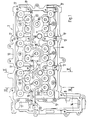
- An internal combustion engine has one placed on a cylinder block 1 Cylinder head arrangement, the housing of three housing components is composed, a basic housing 2, a tappet housing 3 and a cylinder head cover 4.
- the internal combustion engine is in this embodiment in the form of a cylinder bank of a six-cylinder boxer engine with four each Valves per cylinder and two overhead camshafts are shown. This Accordingly, the internal combustion engine has three cylinder bores 5 per cylinder bank. Each of these cylinder bores 5 does not work via four guided in valve guides 6 Gas exchange valves (two inlet valves, two outlet valves) and corresponding gas exchange channels 7 controlled.
- the gas exchange channels 7 and Valve guides 6 are integrated in a base block 8 of the base housing 2, on the a chain case 9 connects at the end.
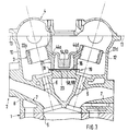
- each shaft 15 is formed, each start from a flange surface 16 and into each of the three cylinder bores 5 flow out. These three shafts 15 serve to receive a spark plug, one Injector or a glow plug.
- In the basic housing 2 are still each Camshaft (not shown in detail) or four lower bearing block halves for each valve row 17 trained, which face each other in pairs.
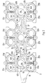
- the tappet housing 3 In the limited by the outer walls 10 to 12 and the chain case 9 Interior of the base housing 2, the tappet housing 3 is used, which with a flange surface 18 rests on the flange surface 16 of the basic housing 2.
- the both flange surfaces 16 and 18 form a common flange plane 19 and are separated from one another by an interposed seal 20.
- the Cup tappet housing 3 is formed in one piece and has a flange surface 19 having central web 21, with the five tappet guides 22a per cylinder bore 5 to 22d are connected, which are combined in pairs.
- In Mittelsteg 21 three bores 23 are formed, which are connected to the shafts 15 of the basic housing 2 swear.
- the cylinder head assembly is completed by the cylinder head cover 4, the is placed on the outer walls 10 to 12 and 14.
- the upper bracket halves 24 are formed, which together with the Basic housing 2 formed lower bearing block halves 17 which are not closer store the camshafts shown.
- a dashed line opens into the flange surface 16 of the basic housing Pressure channel 25, the in a manner not shown with a riser Oil supply in cylinder block 1 is connected.
- This blind bore 28 is over a Annular channel 29 with the input side of one inserted in the central web 21
- Control valve 30 connected (Fig. 5). This is also shown schematically in FIG. 6
- Control valve 30 is connected to one of its outputs via a check valve 31 Interior of the cylinder head assembly connected.
- the second exit is at the end of the control valve 30 via a bore 32 with a molded recess 33 in the flange surface 19 of the tappet housing 3 connected.
- This recess 33 is on the other hand, via an opening 34 in the seal 20 with a further recess 35 connected in the flange surface 16 of the basic housing.
- the other end of the Recess 35 is via a further opening 36 with a recess 37 in the Flange surface 19 connected via a passage 38 in the seal 20 with a recess 39 is connected in the flange surface 16.
- the recess 33 is over the bore 32 and an opening 40 in the seal 20 additionally with a recess 41 connected in the flange surface 16.
- the depressions 33 and 37 in the Flange surface 19 and the depressions 35, 39 and 41 in the flange surface 16 are inserted through the seal 20 between the two flange surfaces separated from each other. Pressure medium transitions are only in the area of the openings 27, 34, 36, 38 and 40 possible.
- the depressions 33 and 37 on the one hand and 35, 39 and 41 on the other hand thus form together with the seal 20 and the openings 27, 34, 36, 38 and 40 a channel 42, which is connected to the control connection of the control valve 30.
- This channel 42 is in the area of the tappet guides 22b of a respective cylinder via a channel 43b in the central web 21 and an outgoing oblique bore 44b with the respective tappet guide 22b and is used for pressure medium and Lubricant supply to the cup tappets 45b shown schematically in FIG. 6.
- These tappets can be used as conventional tappets known per se or as also known switchable or switchable tappets can be formed.
- Switchable bucket tappet is to be understood as one with which Valve stroke of the associated gas exchange valve switched on or off completely can be.
- Switchable bucket tappets mean one with which the valve lift of the associated gas exchange valve varies in at least two stages can be.
- each of the three cylinder bores 5 or bores 23 Three channels 43a, 43c and 43d each open into this recess 53. Of these Channels in the central web 21 each have an oblique bore 44a, 44c and 44d to supply the associated ram guide 22a, 22c, 22d or the Cup tappet 45a, 45c and 45d is used.
- These ram guides can also be used known plunger elements in switchable, switchable or non-switchable Execution can be used. It can make sense if, for example, that each assigned inlet valve with a switchable or switchable Tappet element is provided while the associated exhaust valves are not switchable plunger elements are operated.
- the depression 53 thus forms, together with the seal 20, a channel 54 which is connected to the control port of the second control valve 50 is connected.
- This channel 54 serves together with the channels 43a, 43c and 43d and the oblique bores 44a, 44c and 44d the pressure and lubricant supply to the tappet guides 22a, 22c and 22d or the tappet 45a, 45c and 45d.
- the ring channel 29 on the first control valve 30 is through a bore 55 with a short Recess 56 connected in the flange surface 19.
- This depression 56 is in turn via an opening 57 in the seal 20 with a recess 58 in the flange surface connected, which leads to the area of the chain case 9.
- a Oil supply from the front in this embodiment in the area of Chain box arranged components possible.
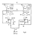
- the oil supply to the cylinder head arrangement is in Fig. 6 for the four Cup tappets 45a to 45d (stroke transmission elements) of two cylinders schematically shown.
- the tappets 45 a and 45 b are each switchable elements trained (stroke switchover or lift cutoff).
- the exhaust valves associated tappets 45c and 45d are not in this embodiment switchable.
- the oil pump 60 of the internal combustion engine delivers oil from the oil pan 61der Internal combustion engine via a riser 62 in the cylinder block 1 in the Cylinder head arrangement.
- the two switching valves 30 and 50 are on previously pressure described on the input side. In the unswitched The condition of both switching valves is the input side with the check valve 31 or 51 connected.
- the check valves are designed so that they are only at Open when a specified pressure is exceeded. This opening pressure is lower than the switching pressure of the bucket tappet or the one integrated in the circuit Switching elements. Together with a throttle line 63 or 64 between the Riser 62 and the channel 42 and 54 is thus ensured that one for the Lubrication does not require pressure within the cylinder head assembly is undercut.
- the respectively assigned channel 42 or 54 is thus also connected the delivery pressure of the oil pump 60 is applied. This is a toggle assigned switchable bucket tappets (stroke transmission elements) possible.
- the in the Flange level 19 not only formed independent channel sections or channels the supply of tappet elements in their respective embodiment possible. It is easily possible for other consumers within the To supply cylinder head assembly with pressure medium or lubricant. You can for example, all lubrication points in the area of the valve train. It is still possible by separating the individual channels or channel sections to supply different consumers with pressure medium or lubricant. This can in particular switchable valve lift transmission elements, such as Rocker arm, rocker arm or the like. It is still possible, alternatively or in addition, the pressure supply of valve phase control elements via one of these Channels or channel sections.
- the arrangement offers different channels and channel sections within the flange level or within the flange surfaces separated by the seal Possibility to lubricate different consumers independently or to supply pressure medium. It is in contrast to what is shown here Embodiment also possible, the lubricating oil supply and pressure control switchable consumers (e.g. switchable valve lift transmission elements) independently from each other by separate exposure via separate channels or lines to make. This consumer is supplied with lubricating oil via the first lines provided. Hydraulic can then also be used via these first lines Valve clearance compensation elements are applied. Via a second line then the pressure control of switching elements take place. These lines are then for example, each connected to one of the channels, so that pressure and Volume flow independently of each other to the different requirements can be adjusted.
- the lubricating oil supply and pressure control switchable consumers e.g. switchable valve lift transmission elements
Landscapes
- Engineering & Computer Science (AREA)
- Mechanical Engineering (AREA)
- General Engineering & Computer Science (AREA)
- Chemical & Material Sciences (AREA)
- Combustion & Propulsion (AREA)
- Lubrication Of Internal Combustion Engines (AREA)
- Cylinder Crankcases Of Internal Combustion Engines (AREA)
- Valve-Gear Or Valve Arrangements (AREA)
Claims (7)
- Culasse d'un moteur à combustion interne comportant au moins deux composants de boítier (2, 3, 4), qui présentent un plan de bridage (19) commun, dans lequel est formé au moins un canal d'alimentation en huile (42, 54, 59), caractérisée en ce que dans le plan de bridage commun, sont formés au moins deux canaux (42, 54, 59) séparés, qui sont séparés l'un de l'autre par une garniture d'étanchéité (20) placée entre eux, un premier canal (42) étant formé entre la garniture d'étanchéité (20) et le premier composant de boítier (3), et un deuxième canal (54, 59) se trouve entre la garniture d'étanchéité et le deuxième composant de boítier (2).
- Culasse selon la revendication 1, caractérisée en ce que dans la garniture d'étanchéité (20) est formé au moins un passage (7, 34, 36, 38, 40) par lequel des tronçons (33, 35, 37, 39, 41) individuels d'au moins l'un des canaux (42) sont reliés entre eux.
- Culasse selon l'une des revendications précédentes, caractérisée en ce que l'un des composants du boítier est un boítier de base (2), qui présente des canaux d'échange des gaz (7) et des guides de soupape (6) et qui est placé sur un bloc-cylindres (1).
- Culasse selon l'une des revendications précédentes, caractérisée en ce que les canaux (42, 54, 59) sont formés, au moins par endroits, par des renfoncements (26, 33, 35, 37, 39, 41, 47, 56) coulés à l'intérieur de la surface de bridage du composant de boítier correspondant.
- Culasse selon l'une des revendications précédentes, caractérisée en ce que dans la culasse au moins deux récepteurs (45a, 45d) sont alimentés en huile séparément l'un de l'autre, par les canaux (42, 54, 59).
- Culasse selon l'une des revendications précédentes, caractérisée en ce que l'un des canaux (42, 54) au moins est relié à une soupape de commande (3à, 50), par laquelle au moins un récepteur (45a, 45b) commandable est alimenté à l'intérieur de la culasse.
- Culasse selon l'une des revendications précédentes, caractérisée en ce que le récepteur commandable est un élément à commande hydraulique pour la variation de la course des soupapes.
Applications Claiming Priority (2)
| Application Number | Priority Date | Filing Date | Title |
|---|---|---|---|
| DE19618401 | 1996-05-08 | ||
| DE19618401A DE19618401C1 (de) | 1996-05-08 | 1996-05-08 | Zylinderkopfanordnung einer Brennkraftmaschine |
Publications (2)
| Publication Number | Publication Date |
|---|---|
| EP0806562A1 EP0806562A1 (fr) | 1997-11-12 |
| EP0806562B1 true EP0806562B1 (fr) | 2001-03-21 |
Family
ID=7793649
Family Applications (1)
| Application Number | Title | Priority Date | Filing Date |
|---|---|---|---|
| EP97106334A Expired - Lifetime EP0806562B1 (fr) | 1996-05-08 | 1997-04-17 | Culasse pour moteur à combustion interne |
Country Status (5)
| Country | Link |
|---|---|
| US (1) | US5845616A (fr) |
| EP (1) | EP0806562B1 (fr) |
| JP (1) | JPH1047155A (fr) |
| KR (1) | KR100456766B1 (fr) |
| DE (2) | DE19618401C1 (fr) |
Families Citing this family (10)
| Publication number | Priority date | Publication date | Assignee | Title |
|---|---|---|---|---|
| JPH10331709A (ja) * | 1997-05-29 | 1998-12-15 | Suzuki Motor Corp | 内燃機関のシリンダヘッド構造 |
| US6099374A (en) * | 1997-08-14 | 2000-08-08 | Sanshin Kogyo Kabushiki Kaisha | Lubrication and oil drain system for 4 cycle outboard motor |
| US6123055A (en) * | 1998-02-25 | 2000-09-26 | Isuzu Motors Limited | Cylinder head structure |
| DE19828307A1 (de) * | 1998-06-25 | 1999-12-30 | Porsche Ag | Zylinderkopf einer Brennkraftmaschine |
| US6257188B1 (en) * | 1998-09-02 | 2001-07-10 | Honda Giken Kogyo Kabushiki Kaisha | Structure for mounting cylinder head cover of internal combustion engine |
| JP4627304B2 (ja) * | 2007-02-01 | 2011-02-09 | 愛知機械工業株式会社 | シリンダヘッドおよびこれを備える内燃機関 |
| DE102007062280A1 (de) * | 2007-12-21 | 2009-06-25 | Daimler Ag | Zylinderkopfeinheit |
| EP2177723A1 (fr) * | 2008-10-17 | 2010-04-21 | GE Jenbacher GmbH & Co. OHG | Guidage de poussoir |
| US8371260B2 (en) * | 2010-05-17 | 2013-02-12 | GM Global Technology Operations LLC | Cylinder head drain and vent |
| US10113502B2 (en) * | 2015-09-08 | 2018-10-30 | Ford Global Technologies, Llc | Cylinder head for an internal combustion engine |
Family Cites Families (5)
| Publication number | Priority date | Publication date | Assignee | Title |
|---|---|---|---|---|
| JPS6079141A (ja) * | 1983-10-04 | 1985-05-04 | Honda Motor Co Ltd | Dohc型4サイクル内燃機関のシリンダヘツド |
| US4883027A (en) * | 1987-11-25 | 1989-11-28 | Honda Giken Kogyo Kabushiki Kaisha | Valve operating system for internal combustion engines |
| JPH07127419A (ja) * | 1993-10-29 | 1995-05-16 | Suzuki Motor Corp | エンジンのオイル通路装置 |
| DE4421057C1 (de) * | 1994-06-16 | 1995-09-14 | Porsche Ag | Zylinderkopfanordnung einer Brennkraftmaschine |
| DE4435299A1 (de) * | 1994-10-01 | 1996-04-04 | Bayerische Motoren Werke Ag | Reihen-Zylinderkopf mit gegossenem Öl-Längskanal |
-
1996
- 1996-05-08 DE DE19618401A patent/DE19618401C1/de not_active Expired - Fee Related
-
1997
- 1997-04-17 EP EP97106334A patent/EP0806562B1/fr not_active Expired - Lifetime
- 1997-04-17 DE DE59703163T patent/DE59703163D1/de not_active Expired - Fee Related
- 1997-05-07 KR KR1019970017495A patent/KR100456766B1/ko not_active Expired - Fee Related
- 1997-05-07 JP JP9117148A patent/JPH1047155A/ja active Pending
- 1997-05-08 US US08/853,345 patent/US5845616A/en not_active Expired - Fee Related
Also Published As
| Publication number | Publication date |
|---|---|
| US5845616A (en) | 1998-12-08 |
| DE59703163D1 (de) | 2001-04-26 |
| EP0806562A1 (fr) | 1997-11-12 |
| KR100456766B1 (ko) | 2005-04-06 |
| KR970075288A (ko) | 1997-12-10 |
| JPH1047155A (ja) | 1998-02-17 |
| DE19618401C1 (de) | 1997-07-03 |
Similar Documents
| Publication | Publication Date | Title |
|---|---|---|
| DE102012219851B4 (de) | Viertaktmotor | |
| DE112020004972T5 (de) | Variable Ventiltriebsvorrichtung eines Motors und Motor | |
| DE102009009149B4 (de) | Ölsystem zum wahlweisen Abschalten von Ventilen für angegebene Zylinder | |
| EP0806552B1 (fr) | Culasse pour moteur à combustion interne | |
| EP0806562B1 (fr) | Culasse pour moteur à combustion interne | |
| DE10000750B4 (de) | Mehrzylindermotor für ein Motorrad | |
| EP0688946B1 (fr) | Agencement d'une culasse d'un moteur à combustion interne | |
| DE19819431B4 (de) | Ölkanalstruktur für einen Motor | |
| DE3203312A1 (de) | Schmiersystem fuer einen verbrennungsmotor | |
| DE69007715T2 (de) | Zylinderkopf für eine Brennkraftmaschine. | |
| DE102005048566A1 (de) | Selbstzündende Brennkraftmaschine mit Brennräumen für hohe Zünddrücke | |
| DE69414557T2 (de) | Zylinderkopfanordnung für eine Mehrventil-Brennkraftmaschine mit obenliegender Nockenwelle | |
| EP0515925B1 (fr) | Culasse pour moteur à combustion | |
| DE19519601C2 (de) | Ventilantriebssytem für eine mehrzylindrige Brennkraftmaschine | |
| DE3604667A1 (de) | Gegossener zylinderkopf fuer eine mehrzylindrige reihen-brennkraftmaschine | |
| EP0744531B1 (fr) | Culasse pour une machine à combustion interne | |
| EP0180847B1 (fr) | Boîtier de commande pour culasse des moteurs à combustion interne avec des soupapes agencées en parallèle | |
| DE3223834C2 (de) | Hydraulische Ventilspiel-Ausgleichseinrichtung für eine Brennkraftmaschine | |
| DE102004034912B4 (de) | Zylinderkopfstruktur eines Motors | |
| EP0845582A1 (fr) | Commande de soupape pour un moteur à combustion interne équipé de soupapes à levée pour le transfert de charge | |
| DE10000751C2 (de) | Motor mit Ventilruhezustandfunktion | |
| DE69315321T2 (de) | Brennkraftmaschine | |
| DE69100427T2 (de) | Schmierungssystem für die Kontaktfläche von einer Nockenwelle und einem hydraulischen Stössel einer Brennkraftmaschine. | |
| DE4435659A1 (de) | Brennkraftmaschine mit nockenbetätigten, zumindest teilweise abschaltbaren Ladungswechsel-Ventilen | |
| DE19808718A1 (de) | Schmiervorrichtung |
Legal Events
| Date | Code | Title | Description |
|---|---|---|---|
| PUAI | Public reference made under article 153(3) epc to a published international application that has entered the european phase |
Free format text: ORIGINAL CODE: 0009012 |
|
| AK | Designated contracting states |
Kind code of ref document: A1 Designated state(s): DE FR GB IT |
|
| 17P | Request for examination filed |
Effective date: 19980407 |
|
| GRAG | Despatch of communication of intention to grant |
Free format text: ORIGINAL CODE: EPIDOS AGRA |
|
| GRAG | Despatch of communication of intention to grant |
Free format text: ORIGINAL CODE: EPIDOS AGRA |
|
| GRAH | Despatch of communication of intention to grant a patent |
Free format text: ORIGINAL CODE: EPIDOS IGRA |
|
| 17Q | First examination report despatched |
Effective date: 20000724 |
|
| GRAH | Despatch of communication of intention to grant a patent |
Free format text: ORIGINAL CODE: EPIDOS IGRA |
|
| ITF | It: translation for a ep patent filed | ||
| GRAA | (expected) grant |
Free format text: ORIGINAL CODE: 0009210 |
|
| AK | Designated contracting states |
Kind code of ref document: B1 Designated state(s): DE FR GB IT |
|
| GBT | Gb: translation of ep patent filed (gb section 77(6)(a)/1977) |
Effective date: 20010402 |
|
| REF | Corresponds to: |
Ref document number: 59703163 Country of ref document: DE Date of ref document: 20010426 |
|
| ET | Fr: translation filed | ||
| REG | Reference to a national code |
Ref country code: GB Ref legal event code: IF02 |
|
| PLBE | No opposition filed within time limit |
Free format text: ORIGINAL CODE: 0009261 |
|
| STAA | Information on the status of an ep patent application or granted ep patent |
Free format text: STATUS: NO OPPOSITION FILED WITHIN TIME LIMIT |
|
| 26N | No opposition filed | ||
| PGFP | Annual fee paid to national office [announced via postgrant information from national office to epo] |
Ref country code: FR Payment date: 20060411 Year of fee payment: 10 |
|
| PGFP | Annual fee paid to national office [announced via postgrant information from national office to epo] |
Ref country code: GB Payment date: 20060420 Year of fee payment: 10 |
|
| PGFP | Annual fee paid to national office [announced via postgrant information from national office to epo] |
Ref country code: IT Payment date: 20060430 Year of fee payment: 10 |
|
| GBPC | Gb: european patent ceased through non-payment of renewal fee |
Effective date: 20070417 |
|
| PG25 | Lapsed in a contracting state [announced via postgrant information from national office to epo] |
Ref country code: GB Free format text: LAPSE BECAUSE OF NON-PAYMENT OF DUE FEES Effective date: 20070417 |
|
| PG25 | Lapsed in a contracting state [announced via postgrant information from national office to epo] |
Ref country code: FR Free format text: LAPSE BECAUSE OF NON-PAYMENT OF DUE FEES Effective date: 20070430 |
|
| PGFP | Annual fee paid to national office [announced via postgrant information from national office to epo] |
Ref country code: DE Payment date: 20090317 Year of fee payment: 13 |
|
| PG25 | Lapsed in a contracting state [announced via postgrant information from national office to epo] |
Ref country code: IT Free format text: LAPSE BECAUSE OF NON-PAYMENT OF DUE FEES Effective date: 20070417 |
|
| PG25 | Lapsed in a contracting state [announced via postgrant information from national office to epo] |
Ref country code: DE Free format text: LAPSE BECAUSE OF NON-PAYMENT OF DUE FEES Effective date: 20101103 |