EP0806552B1 - Culasse pour moteur à combustion interne - Google Patents
Culasse pour moteur à combustion interne Download PDFInfo
- Publication number
- EP0806552B1 EP0806552B1 EP97106332A EP97106332A EP0806552B1 EP 0806552 B1 EP0806552 B1 EP 0806552B1 EP 97106332 A EP97106332 A EP 97106332A EP 97106332 A EP97106332 A EP 97106332A EP 0806552 B1 EP0806552 B1 EP 0806552B1
- Authority
- EP
- European Patent Office
- Prior art keywords
- oil
- cylinder head
- head according
- cylinder
- supply
- Prior art date
- Legal status (The legal status is an assumption and is not a legal conclusion. Google has not performed a legal analysis and makes no representation as to the accuracy of the status listed.)
- Expired - Lifetime
Links
Images

Classifications
-
- F—MECHANICAL ENGINEERING; LIGHTING; HEATING; WEAPONS; BLASTING
- F02—COMBUSTION ENGINES; HOT-GAS OR COMBUSTION-PRODUCT ENGINE PLANTS
- F02F—CYLINDERS, PISTONS OR CASINGS, FOR COMBUSTION ENGINES; ARRANGEMENTS OF SEALINGS IN COMBUSTION ENGINES
- F02F1/00—Cylinders; Cylinder heads
- F02F1/24—Cylinder heads
- F02F1/42—Shape or arrangement of intake or exhaust channels in cylinder heads
- F02F1/4214—Shape or arrangement of intake or exhaust channels in cylinder heads specially adapted for four or more valves per cylinder
-
- F—MECHANICAL ENGINEERING; LIGHTING; HEATING; WEAPONS; BLASTING
- F01—MACHINES OR ENGINES IN GENERAL; ENGINE PLANTS IN GENERAL; STEAM ENGINES
- F01L—CYCLICALLY OPERATING VALVES FOR MACHINES OR ENGINES
- F01L1/00—Valve-gear or valve arrangements, e.g. lift-valve gear
- F01L1/02—Valve drive
- F01L1/04—Valve drive by means of cams, camshafts, cam discs, eccentrics or the like
- F01L1/047—Camshafts
- F01L1/053—Camshafts overhead type
-
- F—MECHANICAL ENGINEERING; LIGHTING; HEATING; WEAPONS; BLASTING
- F01—MACHINES OR ENGINES IN GENERAL; ENGINE PLANTS IN GENERAL; STEAM ENGINES
- F01L—CYCLICALLY OPERATING VALVES FOR MACHINES OR ENGINES
- F01L1/00—Valve-gear or valve arrangements, e.g. lift-valve gear
- F01L1/26—Valve-gear or valve arrangements, e.g. lift-valve gear characterised by the provision of two or more valves operated simultaneously by same transmitting-gear; peculiar to machines or engines with more than two lift-valves per cylinder
-
- F—MECHANICAL ENGINEERING; LIGHTING; HEATING; WEAPONS; BLASTING
- F01—MACHINES OR ENGINES IN GENERAL; ENGINE PLANTS IN GENERAL; STEAM ENGINES
- F01L—CYCLICALLY OPERATING VALVES FOR MACHINES OR ENGINES
- F01L1/00—Valve-gear or valve arrangements, e.g. lift-valve gear
- F01L1/02—Valve drive
- F01L1/04—Valve drive by means of cams, camshafts, cam discs, eccentrics or the like
- F01L1/047—Camshafts
- F01L2001/0476—Camshaft bearings
-
- F—MECHANICAL ENGINEERING; LIGHTING; HEATING; WEAPONS; BLASTING
- F01—MACHINES OR ENGINES IN GENERAL; ENGINE PLANTS IN GENERAL; STEAM ENGINES
- F01L—CYCLICALLY OPERATING VALVES FOR MACHINES OR ENGINES
- F01L1/00—Valve-gear or valve arrangements, e.g. lift-valve gear
- F01L1/02—Valve drive
- F01L1/04—Valve drive by means of cams, camshafts, cam discs, eccentrics or the like
- F01L1/047—Camshafts
- F01L1/053—Camshafts overhead type
- F01L2001/0537—Double overhead camshafts [DOHC]
-
- F—MECHANICAL ENGINEERING; LIGHTING; HEATING; WEAPONS; BLASTING
- F01—MACHINES OR ENGINES IN GENERAL; ENGINE PLANTS IN GENERAL; STEAM ENGINES
- F01M—LUBRICATING OF MACHINES OR ENGINES IN GENERAL; LUBRICATING INTERNAL COMBUSTION ENGINES; CRANKCASE VENTILATING
- F01M11/00—Component parts, details or accessories, not provided for in, or of interest apart from, groups F01M1/00 - F01M9/00
- F01M11/02—Arrangements of lubricant conduits
-
- F—MECHANICAL ENGINEERING; LIGHTING; HEATING; WEAPONS; BLASTING
- F01—MACHINES OR ENGINES IN GENERAL; ENGINE PLANTS IN GENERAL; STEAM ENGINES
- F01M—LUBRICATING OF MACHINES OR ENGINES IN GENERAL; LUBRICATING INTERNAL COMBUSTION ENGINES; CRANKCASE VENTILATING
- F01M9/00—Lubrication means having pertinent characteristics not provided for in, or of interest apart from, groups F01M1/00 - F01M7/00
- F01M9/10—Lubrication of valve gear or auxiliaries
- F01M9/104—Lubrication of valve gear or auxiliaries of tappets
-
- F—MECHANICAL ENGINEERING; LIGHTING; HEATING; WEAPONS; BLASTING
- F01—MACHINES OR ENGINES IN GENERAL; ENGINE PLANTS IN GENERAL; STEAM ENGINES
- F01M—LUBRICATING OF MACHINES OR ENGINES IN GENERAL; LUBRICATING INTERNAL COMBUSTION ENGINES; CRANKCASE VENTILATING
- F01M9/00—Lubrication means having pertinent characteristics not provided for in, or of interest apart from, groups F01M1/00 - F01M7/00
- F01M9/10—Lubrication of valve gear or auxiliaries
- F01M9/108—Lubrication of valve gear or auxiliaries of auxiliaries
-
- F—MECHANICAL ENGINEERING; LIGHTING; HEATING; WEAPONS; BLASTING
- F02—COMBUSTION ENGINES; HOT-GAS OR COMBUSTION-PRODUCT ENGINE PLANTS
- F02B—INTERNAL-COMBUSTION PISTON ENGINES; COMBUSTION ENGINES IN GENERAL
- F02B1/00—Engines characterised by fuel-air mixture compression
- F02B1/02—Engines characterised by fuel-air mixture compression with positive ignition
- F02B1/04—Engines characterised by fuel-air mixture compression with positive ignition with fuel-air mixture admission into cylinder
-
- F—MECHANICAL ENGINEERING; LIGHTING; HEATING; WEAPONS; BLASTING
- F02—COMBUSTION ENGINES; HOT-GAS OR COMBUSTION-PRODUCT ENGINE PLANTS
- F02B—INTERNAL-COMBUSTION PISTON ENGINES; COMBUSTION ENGINES IN GENERAL
- F02B2275/00—Other engines, components or details, not provided for in other groups of this subclass
- F02B2275/18—DOHC [Double overhead camshaft]
-
- F—MECHANICAL ENGINEERING; LIGHTING; HEATING; WEAPONS; BLASTING
- F02—COMBUSTION ENGINES; HOT-GAS OR COMBUSTION-PRODUCT ENGINE PLANTS
- F02F—CYLINDERS, PISTONS OR CASINGS, FOR COMBUSTION ENGINES; ARRANGEMENTS OF SEALINGS IN COMBUSTION ENGINES
- F02F1/00—Cylinders; Cylinder heads
- F02F1/24—Cylinder heads
- F02F2001/244—Arrangement of valve stems in cylinder heads
- F02F2001/245—Arrangement of valve stems in cylinder heads the valve stems being orientated at an angle with the cylinder axis
-
- F—MECHANICAL ENGINEERING; LIGHTING; HEATING; WEAPONS; BLASTING
- F02—COMBUSTION ENGINES; HOT-GAS OR COMBUSTION-PRODUCT ENGINE PLANTS
- F02F—CYLINDERS, PISTONS OR CASINGS, FOR COMBUSTION ENGINES; ARRANGEMENTS OF SEALINGS IN COMBUSTION ENGINES
- F02F7/00—Casings, e.g. crankcases
- F02F7/006—Camshaft or pushrod housings
Definitions
- the invention relates to a cylinder head arrangement of an internal combustion engine according to the Genus of claim 1.
- DE 43 24 791 A1 describes such a cylinder head arrangement, which consists of a basic housing placed on the cylinder block, one in the basic housing used carrier component and a final cylinder head cover.
- the Carrier component serves to accommodate valve lift transmission elements that are in shape are formed by tappet elements.
- This support member is in the Basic housing used.
- the cylinder head arrangement is replaced by a Cylinder head cover completed at the top, in a common parting plane on flange surfaces of the outer walls of the basic housing and on a flange surface the support member is placed.
- Oil supply channels in the form of depressions within the flange surface trained, which are combined into an oil gallery and for oil supply to the Valve stroke transmission elements are used. (See also DE-C-4 421 057.)
- a similar cylinder head arrangement is described in DE 43 07 368 A1.
- the valve lift transmission elements are guided on the carrier component or stored, the two exhaust valves per cylinder via tappet elements be operated. Two of the three intake valves are also over Cup tappet elements act on the valve lift by suitable control of the associated gas exchange valve can influence.
- the third intake valve is actuated via an actuating lever guided on the carrier component.
- the switchable valve lift transmission elements are hydraulic pressurized and - as is usually the case - also via the oil supply to the Internal combustion engine supplies, there are various problems with regard to Total oil supply to the cylinder head.
- the invention is therefore based on the object, the oil supply within a Generic cylinder head arrangement to improve so that this simple and is inexpensive to manufacture and an at least partially independent supply allows different consumers.
- the drilling effort within the Cylinder head assembly can be minimized and especially on very long, cost and labor-intensive oil drilling can be dispensed with.
- a first oil gallery in the parting plane can be used in a particularly advantageous manner be formed between the base housing and the support member, which on particularly short distances with the oil supply within the cylinder block can be connected.
- Such a first oil gallery will be known per se Rising pipes supplied within the cylinder block is a very direct connection possible, which gets by with very few holes and thus also Keeps throttle losses low.
- the second oil gallery can be advantageously located in the Form cylinder head cover limited parting plane, so that there is a spatial Separation to the first oil gallery results. This is a simple crossing-free supply of a large number of consumers.
- the supply of different consumers who have different requirements in the With regard to oil volume and / or oil pressure, can be particularly advantageous Ways are made possible that within one in the respective parting plane trained oil gallery two or more individual supply lines become. These supply lines can do so in a particularly simple manner be arranged so that they are each in the longitudinal direction of the cylinder head assembly extend and in different flange sections of the respective flange surface are trained.
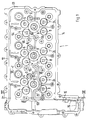
- a multi-cylinder internal combustion engine has a cylinder head arrangement, the Basic housing 1 is screwed to a cylinder block 2.
- the gas exchange of the Internal combustion engine takes place via five gas exchange valves 3 per cylinder, three of which are designed as inlet valves and two as outlet valves.
- the valve guides 4 to 8 of the gas exchange valves 3 are arranged around a central shaft 9 which opens into the combustion chamber 10 and for receiving a spark plug 11, one Injector or a glow plug is used.
- the basic housing 1 has one upwards open, trough-shaped interior, which by three outer walls 12, 13, 14 and Outer walls 15 of an end chain box 16 is included. This chain case 16 is used to accommodate not shown drive means for the two Gas exchange valves 3 actuating camshafts 17 and 18.
- the camshaft 17 is formed as an exhaust camshaft and actuated in the valve guides 7 and 8 guided exhaust valves.
- the camshaft 18 actuates those in the valve guides 4, 5 and 6 guided inlet valves.
- Partition surface Partition surface
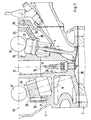
- This parting line 19 is by Flanged surfaces 20 to 22 are formed, each in the combustion chamber 10 Border the opening shaft 9. In this parting plane 19 they are in two rows arranged flange-like end faces of bores 23, 24, which are used for fastening serve a support member 25.
- the one-piece support member 25 has a central web 26 in which three Openings 27 are formed which extend the respective shaft 9. At the The underside of the central web 26 are flange surfaces 28 around the openings 27 formed with the flange surfaces 20 to 22 of the basic housing correspond. The lower end faces of FIG two rows of holes 29, 30 aligned with the holes 20 and 21 and to Attachment of the support member 25 to the basic housing 1 serve.
- the central web 26 of the carrier component 25 is of a U-shaped outer web 31 comprises, which consists of two opposite short web sides 32 and 33 and a longitudinal web 34 connecting them together. Between the longitudinal web 34 and the central web 26, two tappet guides 35, 36 are formed per cylinder, which are arranged in extension of the valve guides 4 and 5. This Tappet guides 35 and 36 serve to accommodate cup tappet elements 37, via which the assigned intake valves are actuated by the camshaft 18. On on the opposite side of the central web there are two more per cylinder Tappet guides 38, 39 are formed, which extend the valve guides 7 and 8 are arranged. These tappet guides are used to hold Cup tappet elements 40, via which the exhaust valves from the camshaft 17th be operated.
- the third inlet valve is via a lever element not variably actuated by the camshaft.
- the exhaust valves are in this Embodiment operated by non-switchable tappet elements. A such valve actuation is, for example, in DE 43 07 368 mentioned at the beginning A1 described.
- the carrier component 25 also serves as the lower one Bearing frame for storing the camshafts 17 and 18.
- the carrier component 25 also serves as the lower one Bearing frame for storing the camshafts 17 and 18.
- the carrier component 25 also serves as the lower one Bearing frame for storing the camshafts 17 and 18.
- Two further crossbars 45 go from the opposite side of the central web 26. In these are corresponding further bearing bores 46 are formed.
- the cylinder head assembly is up through a cylinder head cover 47 completed.
- This lies in a common parting plane 48 on the Outside walls 12 to 15 of the basic housing 1.
- this lies Cylinder head cover 47 on the upper sides of the flange surface Middle web 26, the outer web 31 (longitudinal web 34, short web sides 32, 33) and the crossbars 43 and 45.
- the upper halves are in the cylinder head cover 47 the bearing bores 42, 44 and 46 are formed.
- the cylinder head cover is not over Screws shown in detail with the outer walls 12 to 15 of the Basic housing connected.
- the cylinder head is in the range of Bore holes 42, 44 and 46 or in the region of the short web sides 32 and 33 and the crossbars 43 and 45 with four rows of screw connections 49 to 52 connected to the support member 25.
- the two middle rows of screw connections 50 and 51 penetrate the support member 25 and extend into the Basic housing 1.
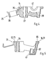
- the oil supply to the cylinder head arrangement takes place via two not shown Risers in cylinder block 2. These risers are each one in the annulus the screw connections of the basic housing 1 to the cylinder block 2. Of these annuli designated 53 and 54 each have an oblique bore 55, 56, of which the oblique bore 55 in a recess 57 in the flange surface 20 flows.
- the second oblique bore 56 opens into a blind bore 58, the Front is designed as a flange surface 59. This flange surface 59 is also located in the parting plane 19.
- the depression 57 extends almost to the chain case 16 and passes into a bore 80.
- transverse channels 60 open into this bore 80 and 61; these transverse channels 60 and 61 are used to supply no closer illustrated consumers within the chain box, such as Chain tensioners and / or for supply from the front on the cylinder head assembly arranged consumers, such as camshaft phasers.
- the groove 57 within the parting plane 19 forms a first oil gallery 62.
- the supply other consumers are not shown here, but possible without further ado.
- a second oil gallery 63 is in the parting plane 48 between the support member 25 and Cylinder head cover 47 formed.
- a first supply line 64 of this oil gallery 63 is essentially formed by a longitudinal groove 65 in the longitudinal web 34. Of This longitudinal groove 65 starts from oblique bores 66, which extend into the tappet guides 36 open and serve to supply oil to the tappet elements arranged therein. Further oblique bores 67, which emanate from this longitudinal groove 65, open into the Lever guide 41 and serve to supply the hydraulic Valve clearance compensation element and the lever guide.
- the through the longitudinal groove 65th Supply line 64 formed is via a in the cylinder head cover 47 trained channel 68 shown schematically in Fig. 2 with a first Control valve 69 connected.
- the input side of this control valve 69 is via a also formed in the cylinder head cover input channel 70 with a bore 71 connected, which extends from the parting plane 48 in the central web 26 and into the Blind hole 58 opens into the basic housing.
- a second supply line 72 of the oil gallery 62 is through a longitudinal groove 73 formed, which is formed from the parting plane 48 in the central web 26. Of this longitudinal groove 73 go short, also formed in the region of the parting plane Connection grooves 74 out. These pass into oblique holes 75, which in the Tappet guides 35 open and to supply those located therein Bucket elements serve. From the longitudinal groove 73 go two more per cylinder Inclined bores 76 and 77, which open into the tappet guides 39 and 38 and serve to supply the tappet elements of the outlet valves.
- the longitudinal groove 73 or the supply line 72 is schematic in FIG. 2 shown channel 76 in the cylinder head cover 47 with the output of a second Control valve 77 connected.
- the input side of the second control valve 77 is over an inlet channel 78 connected to a bore 79.
- This bore 79 runs from the parting line 48 starting in the central web 26 and opens in the area of Oblique bore 55 in the recess 57 of the basic housing 1.
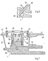
- the two control valves 69 and 77 are designed so that they are in their first Switch position the oil flow in the downstream supply line 64 or 72 throttle so that a specified limit pressure is not exceeded.
- This Limit pressure is designed so that the switching function of the switchable Valve stroke transmission elements (bucket tappet elements) just did not take place. One for However, this will provide sufficient oil supply for lubrication purposes guaranteed.
- In the second switching position of the switching valves 69 and 77 respectively both supply lines with the full delivery pressure of the oil supply Internal combustion engine or the oil pump, so that switching the hydraulically switchable bucket tappet elements.
- the two can each Switchable cup tappet elements provided independently of one another be switched. It is also possible to control the control valve (s) in the cylinder head cover or another component of the cylinder head arrangement integrate.
- switchable tappet elements other hydraulically operated elements for valve stroke control, e.g. switchable rocker arm elements, Rocker arms or similar valve lift transmission elements. It is also possible that Reduce the number of switching elements per cylinder or multiple switching elements switch together and connect to a supply line. In the Formation of a single switching element per cylinder can then, for example one of the switching valves can be dispensed with. Instead of the controllable pressure supply of switching elements for influencing valve lift can be one of the supply lines also serve to control camshaft phase control elements.
Landscapes
- Engineering & Computer Science (AREA)
- Mechanical Engineering (AREA)
- General Engineering & Computer Science (AREA)
- Chemical & Material Sciences (AREA)
- Combustion & Propulsion (AREA)
- Cylinder Crankcases Of Internal Combustion Engines (AREA)
- Valve-Gear Or Valve Arrangements (AREA)
- Lubrication Of Internal Combustion Engines (AREA)
- Lubrication Details And Ventilation Of Internal Combustion Engines (AREA)
Claims (11)
- Culasse d'un moteur à combustion interne, comportant au moins trois composants de boítier, un boítier de base (1) placé sur un bloc-cylindres (2), un couvercle de culasse (47) et un composant porteur (25) destiné à recevoir des éléments de transmission de la course des soupapes, comportant au moins un plan de séparation (19, 48) commun entre deux composants du boítier qui s'appliquent l'un contre l'autre par leurs surfaces de bridage respectives, et comportant des canaux (57, 65, 73) d'alimentation en huile à l'intérieur de la culasse, qui sont réunis au moins en une galerie à huile (62, 63), caractérisée en ce que deux plans de séparation (19, 48) au moins sont formés entre des composants adjacents du boítier, dans chacun des deux plans de séparation, des rainures (57, 65, 63) qui servent de canaux d'alimentation en huile et qui forment deux galeries à huile (62, 63) pour alimenter différents récepteurs, étant ménagées dans au moins l'une des surfaces de bridage correspondantes.
- Culasse, selon la revendication 1, caractérisée en ce que la première galerie à huile (62) s'étend dans un premier plan de séparation (19), qui est formé entre le boítier de base (1) et le composant porteur (25).
- Culasse selon l'une des revendications précédentes, caractérisée en ce que la deuxième galerie à huile (63) s'étend dans un deuxième plan de séparation (48), qui est fermé vers le haut par le couvercle de culasse (47).
- Culasse selon l'une des revendications précédentes, caractérisée en ce que deux lignes d'alimentation en huile (64, 72) indépendantes sont formées dans l'un au moins des deux plans de séparation (19, 48), à l'intérieur de la galerie à huile (62, 63) respective.
- Culasse selon l'une des revendications précédentes, caractérisée en ce que le composant porteur (25) et le couvercle de culasse (47) s'appliquent l'un contre l'autre dans le deuxième plan de séparation (48).
- Culasse selon l'une des revendications précédentes, caractérisée en ce que l'une au moins des galeries à huile (62, 63) sert à alimenter des éléments de commutation, au moyen desquels il est possible d'influencer la transmission de la course à des soupapes d'échange des gaz correspondantes.
- Culasse selon l'une des revendications précédentes, caractérisée en ce qu'un groupe d'éléments de commutation, au moyen desquels la transmission de la course à des soupapes d'échange des gaz correspondantes peut être influencée, peut être commandé hydrauliquement par au moins l'une des deux lignes d'alimentation en huile (64, 72), dans la galerie à huile (63) commune.
- Culasse selon l'une des revendications précédentes, caractérisée en ce que deux groupes différents d'éléments de commutation au moyen desquels la transmission de la course à des soupapes d'échange des gaz peut être influencée, sont commandables hydrauliquement au moyen des deux lignes d'alimentation en huile (64, 72).
- Culasse selon l'une des revendications précédentes, caractérisée en ce qu'une alimentation de récepteurs associés s'effectue, par au moins l'une des galeries à huile (62, 63), en ce qu'il se produit simultanément une lubrification et une commande de la pression.
- Culasse selon l'une des revendications précédentes, caractérisée en ce que la pression de l'huile peut être commandée au moyen d'une soupape de commande (69, 77) associée, dans l'une au moins des lignes d'alimentation en huile (64, 72).
- Culasse selon l'une des revendications précédentes, caractérisée en ce que la pression de l'huile peut être commandée au moyen d'au moins une soupape de commande (69, 77) associée, dans l'une au moins des galeries à huile (62, 63).
Applications Claiming Priority (2)
| Application Number | Priority Date | Filing Date | Title |
|---|---|---|---|
| DE19619183 | 1996-05-11 | ||
| DE19619183A DE19619183C1 (de) | 1996-05-11 | 1996-05-11 | Zylinderkopfanordnung einer Brennkraftmaschine |
Publications (2)
| Publication Number | Publication Date |
|---|---|
| EP0806552A1 EP0806552A1 (fr) | 1997-11-12 |
| EP0806552B1 true EP0806552B1 (fr) | 2001-03-21 |
Family
ID=7794141
Family Applications (1)
| Application Number | Title | Priority Date | Filing Date |
|---|---|---|---|
| EP97106332A Expired - Lifetime EP0806552B1 (fr) | 1996-05-11 | 1997-04-17 | Culasse pour moteur à combustion interne |
Country Status (5)
| Country | Link |
|---|---|
| US (1) | US5875754A (fr) |
| EP (1) | EP0806552B1 (fr) |
| JP (1) | JPH1047156A (fr) |
| KR (1) | KR100456767B1 (fr) |
| DE (2) | DE19619183C1 (fr) |
Families Citing this family (15)
| Publication number | Priority date | Publication date | Assignee | Title |
|---|---|---|---|---|
| JPH10331709A (ja) * | 1997-05-29 | 1998-12-15 | Suzuki Motor Corp | 内燃機関のシリンダヘッド構造 |
| DE19828307A1 (de) * | 1998-06-25 | 1999-12-30 | Porsche Ag | Zylinderkopf einer Brennkraftmaschine |
| JP2000087796A (ja) * | 1998-09-14 | 2000-03-28 | Honda Motor Co Ltd | Dohc式エンジンのシリンダヘッド |
| DE19928838C1 (de) * | 1999-06-24 | 2001-02-15 | Otmar Gaehrken | Zylinderkopf |
| JP4396024B2 (ja) * | 2000-03-13 | 2010-01-13 | マツダ株式会社 | シリンダヘッド構造 |
| DE10327542B4 (de) * | 2002-06-29 | 2008-11-06 | Hyundai Motor Company | Ölzuführstruktur für einen Motorzylinderkopf |
| JP4244597B2 (ja) * | 2002-08-27 | 2009-03-25 | トヨタ自動車株式会社 | 内燃機関 |
| DE10250303A1 (de) * | 2002-10-29 | 2004-05-19 | Bayerische Motoren Werke Ag | Zylinderkopf einer Brennkraftmaschine mit Nockenwellenlagerleiste |
| DE102004005796B4 (de) * | 2004-02-06 | 2014-01-16 | Daimler Ag | Zylinderkopf für eine Brennkraftmaschine |
| US20070137604A1 (en) * | 2005-12-21 | 2007-06-21 | Silseth John R | Motorcycle engine |
| US7360512B1 (en) | 2006-12-22 | 2008-04-22 | Chrysler Llc | Low-thermal-inertia intake ports for port-injected, spark ignition engines and an associated manufacturing method |
| JP2011080384A (ja) * | 2009-10-05 | 2011-04-21 | Otics Corp | 車両用エンジン |
| DE102011079166A1 (de) | 2011-07-14 | 2013-01-17 | Mahle International Gmbh | Brennkraftmaschine |
| DE102015109802A1 (de) | 2015-06-18 | 2016-12-22 | Dr. Ing. H.C. F. Porsche Aktiengesellschaft | Brennkraftmaschine |
| DE102016201414B4 (de) | 2016-01-29 | 2017-10-05 | Ford Global Technologies, Llc | Brennkraftmaschine mit Ölkreislauf |
Family Cites Families (9)
| Publication number | Priority date | Publication date | Assignee | Title |
|---|---|---|---|---|
| DE3641129C1 (de) * | 1986-12-02 | 1987-07-30 | Daimler Benz Ag | Vorrichtung zur Lagerung von zwei Nockenwellen im Zylinderkopf einer mehrzylindrigen Reihenbrennkraftmaschine |
| CA1331547C (fr) * | 1988-08-01 | 1994-08-23 | Yukihiro Matsumoto | Systeme de distribution pour moteur a combustion interne |
| JPH0482343U (fr) * | 1990-11-29 | 1992-07-17 | ||
| DE4116942C1 (en) * | 1991-05-24 | 1992-05-27 | Mercedes-Benz Aktiengesellschaft, 7000 Stuttgart, De | Cylinder head for multicylinder IC engine - has accessory cover bolts with oil bores for guiding oil to bearing points and valve tappets |
| DE4307368A1 (de) * | 1993-03-09 | 1994-09-15 | Porsche Ag | Zylinderkopf für eine Brennkraftmaschine |
| DE4324791A1 (de) * | 1993-07-23 | 1995-01-26 | Porsche Ag | Zylinderkopfanordnung einer Brennkraftmaschine |
| JP3104497B2 (ja) * | 1993-09-30 | 2000-10-30 | スズキ株式会社 | シリンダヘッドの構造 |
| DE4421057C1 (de) * | 1994-06-16 | 1995-09-14 | Porsche Ag | Zylinderkopfanordnung einer Brennkraftmaschine |
| US5458100A (en) * | 1994-11-10 | 1995-10-17 | Kohler Co. | Pilot ring attachment assembly |
-
1996
- 1996-05-11 DE DE19619183A patent/DE19619183C1/de not_active Expired - Fee Related
-
1997
- 1997-04-17 DE DE59703162T patent/DE59703162D1/de not_active Expired - Fee Related
- 1997-04-17 EP EP97106332A patent/EP0806552B1/fr not_active Expired - Lifetime
- 1997-05-09 JP JP9119753A patent/JPH1047156A/ja not_active Withdrawn
- 1997-05-10 KR KR1019970018128A patent/KR100456767B1/ko not_active Expired - Fee Related
- 1997-05-12 US US08/854,588 patent/US5875754A/en not_active Expired - Fee Related
Also Published As
| Publication number | Publication date |
|---|---|
| KR100456767B1 (ko) | 2005-04-06 |
| JPH1047156A (ja) | 1998-02-17 |
| EP0806552A1 (fr) | 1997-11-12 |
| DE59703162D1 (de) | 2001-04-26 |
| US5875754A (en) | 1999-03-02 |
| KR970075289A (ko) | 1997-12-10 |
| DE19619183C1 (de) | 1997-07-03 |
Similar Documents
| Publication | Publication Date | Title |
|---|---|---|
| EP0806552B1 (fr) | Culasse pour moteur à combustion interne | |
| DE3436426C2 (fr) | ||
| DE102012219851B4 (de) | Viertaktmotor | |
| DE3515850A1 (de) | Ventilbetaetigungseinrichtung fuer eine obengesteuerte brennkraftmaschine | |
| DE69025368T2 (de) | Mehrventil-Brennkraftmaschine | |
| DE10000750B4 (de) | Mehrzylindermotor für ein Motorrad | |
| DE3203312A1 (de) | Schmiersystem fuer einen verbrennungsmotor | |
| EP0688946B1 (fr) | Agencement d'une culasse d'un moteur à combustion interne | |
| DE10212327A1 (de) | Ventiltrieb für eine Brennkraftmaschine | |
| DE4410123C2 (de) | Ölversorgung bei einer Ventilbetätigungseinrichtung | |
| DE69024117T2 (de) | Zylinderkopf-Schmiersystem einer Brennkraftmaschine | |
| DE102005048566A1 (de) | Selbstzündende Brennkraftmaschine mit Brennräumen für hohe Zünddrücke | |
| DE19618401C1 (de) | Zylinderkopfanordnung einer Brennkraftmaschine | |
| DE19519601C2 (de) | Ventilantriebssytem für eine mehrzylindrige Brennkraftmaschine | |
| EP0845582B1 (fr) | Commande de soupape pour un moteur à combustion interne équipé de soupapes à levée pour le transfert de charge | |
| DE19744600A1 (de) | Abschaltbarer Ventiltrieb für Brennkraftmaschinen | |
| DE4204997A1 (de) | Ventiltrieb fuer ein hubventil | |
| DE10002512A1 (de) | Zylinderkopf für eine ventilgesteuerte Brennkraftmaschine | |
| DE4235103B4 (de) | Nockenwellen-Ventilsteuerung für eine Brennkraftmaschine mit zwei Zylinderreihen | |
| EP1427918B1 (fr) | Distribution dans moteur a combustion interne | |
| EP0990776B1 (fr) | Moteur à combustion interne à 2 rangées de cylindres disposées en V | |
| DE10302663B4 (de) | Ventiltriebsanordnung für eine Brennkraftmaschine | |
| DE4244374A1 (de) | Ventilsteuerung | |
| DE4435659A1 (de) | Brennkraftmaschine mit nockenbetätigten, zumindest teilweise abschaltbaren Ladungswechsel-Ventilen | |
| DE69315321T2 (de) | Brennkraftmaschine |
Legal Events
| Date | Code | Title | Description |
|---|---|---|---|
| PUAI | Public reference made under article 153(3) epc to a published international application that has entered the european phase |
Free format text: ORIGINAL CODE: 0009012 |
|
| AK | Designated contracting states |
Kind code of ref document: A1 Designated state(s): DE FR GB IT |
|
| 17P | Request for examination filed |
Effective date: 19980407 |
|
| GRAG | Despatch of communication of intention to grant |
Free format text: ORIGINAL CODE: EPIDOS AGRA |
|
| GRAG | Despatch of communication of intention to grant |
Free format text: ORIGINAL CODE: EPIDOS AGRA |
|
| GRAH | Despatch of communication of intention to grant a patent |
Free format text: ORIGINAL CODE: EPIDOS IGRA |
|
| 17Q | First examination report despatched |
Effective date: 20000726 |
|
| GRAH | Despatch of communication of intention to grant a patent |
Free format text: ORIGINAL CODE: EPIDOS IGRA |
|
| ITF | It: translation for a ep patent filed | ||
| GRAA | (expected) grant |
Free format text: ORIGINAL CODE: 0009210 |
|
| AK | Designated contracting states |
Kind code of ref document: B1 Designated state(s): DE FR GB IT |
|
| PGFP | Annual fee paid to national office [announced via postgrant information from national office to epo] |
Ref country code: GB Payment date: 20010411 Year of fee payment: 5 |
|
| PGFP | Annual fee paid to national office [announced via postgrant information from national office to epo] |
Ref country code: DE Payment date: 20010426 Year of fee payment: 5 |
|
| REF | Corresponds to: |
Ref document number: 59703162 Country of ref document: DE Date of ref document: 20010426 |
|
| ET | Fr: translation filed | ||
| PGFP | Annual fee paid to national office [announced via postgrant information from national office to epo] |
Ref country code: FR Payment date: 20010430 Year of fee payment: 5 |
|
| GBT | Gb: translation of ep patent filed (gb section 77(6)(a)/1977) |
Effective date: 20010423 |
|
| REG | Reference to a national code |
Ref country code: GB Ref legal event code: IF02 |
|
| PLBE | No opposition filed within time limit |
Free format text: ORIGINAL CODE: 0009261 |
|
| STAA | Information on the status of an ep patent application or granted ep patent |
Free format text: STATUS: NO OPPOSITION FILED WITHIN TIME LIMIT |
|
| 26N | No opposition filed | ||
| PG25 | Lapsed in a contracting state [announced via postgrant information from national office to epo] |
Ref country code: GB Free format text: LAPSE BECAUSE OF NON-PAYMENT OF DUE FEES Effective date: 20020417 |
|
| PG25 | Lapsed in a contracting state [announced via postgrant information from national office to epo] |
Ref country code: DE Free format text: LAPSE BECAUSE OF NON-PAYMENT OF DUE FEES Effective date: 20021101 |
|
| GBPC | Gb: european patent ceased through non-payment of renewal fee |
Effective date: 20020417 |
|
| PG25 | Lapsed in a contracting state [announced via postgrant information from national office to epo] |
Ref country code: FR Free format text: LAPSE BECAUSE OF NON-PAYMENT OF DUE FEES Effective date: 20021231 |
|
| REG | Reference to a national code |
Ref country code: FR Ref legal event code: ST |
|
| PG25 | Lapsed in a contracting state [announced via postgrant information from national office to epo] |
Ref country code: IT Free format text: LAPSE BECAUSE OF NON-PAYMENT OF DUE FEES;WARNING: LAPSES OF ITALIAN PATENTS WITH EFFECTIVE DATE BEFORE 2007 MAY HAVE OCCURRED AT ANY TIME BEFORE 2007. THE CORRECT EFFECTIVE DATE MAY BE DIFFERENT FROM THE ONE RECORDED. Effective date: 20050417 |