EP0767295B1 - Commande de soupape hydraulique - Google Patents
Commande de soupape hydraulique Download PDFInfo
- Publication number
- EP0767295B1 EP0767295B1 EP95810620A EP95810620A EP0767295B1 EP 0767295 B1 EP0767295 B1 EP 0767295B1 EP 95810620 A EP95810620 A EP 95810620A EP 95810620 A EP95810620 A EP 95810620A EP 0767295 B1 EP0767295 B1 EP 0767295B1
- Authority
- EP
- European Patent Office
- Prior art keywords
- hydraulic
- piston
- cylinder
- drive
- valve
- Prior art date
- Legal status (The legal status is an assumption and is not a legal conclusion. Google has not performed a legal analysis and makes no representation as to the accuracy of the status listed.)
- Expired - Lifetime
Links
- 239000012530 fluid Substances 0.000 claims description 19
- 238000013016 damping Methods 0.000 claims description 6
- 239000010720 hydraulic oil Substances 0.000 description 10
- 238000010586 diagram Methods 0.000 description 3
- 238000004519 manufacturing process Methods 0.000 description 3
- 230000001360 synchronised effect Effects 0.000 description 3
- 230000009471 action Effects 0.000 description 1
- 230000008901 benefit Effects 0.000 description 1
- 230000008859 change Effects 0.000 description 1
- 238000002485 combustion reaction Methods 0.000 description 1
- 230000001419 dependent effect Effects 0.000 description 1
- 238000011161 development Methods 0.000 description 1
- 230000018109 developmental process Effects 0.000 description 1
- 238000006073 displacement reaction Methods 0.000 description 1
- 230000002996 emotional effect Effects 0.000 description 1
- 238000000227 grinding Methods 0.000 description 1
- 238000007654 immersion Methods 0.000 description 1
- 230000006872 improvement Effects 0.000 description 1
- 238000000034 method Methods 0.000 description 1
- 239000003921 oil Substances 0.000 description 1
- 230000008569 process Effects 0.000 description 1
- 238000010992 reflux Methods 0.000 description 1
- 238000007789 sealing Methods 0.000 description 1
- 239000007787 solid Substances 0.000 description 1
- 239000006228 supernatant Substances 0.000 description 1
Images

Classifications
-
- F—MECHANICAL ENGINEERING; LIGHTING; HEATING; WEAPONS; BLASTING
- F01—MACHINES OR ENGINES IN GENERAL; ENGINE PLANTS IN GENERAL; STEAM ENGINES
- F01L—CYCLICALLY OPERATING VALVES FOR MACHINES OR ENGINES
- F01L1/00—Valve-gear or valve arrangements, e.g. lift-valve gear
- F01L1/26—Valve-gear or valve arrangements, e.g. lift-valve gear characterised by the provision of two or more valves operated simultaneously by same transmitting-gear; peculiar to machines or engines with more than two lift-valves per cylinder
-
- F—MECHANICAL ENGINEERING; LIGHTING; HEATING; WEAPONS; BLASTING
- F01—MACHINES OR ENGINES IN GENERAL; ENGINE PLANTS IN GENERAL; STEAM ENGINES
- F01L—CYCLICALLY OPERATING VALVES FOR MACHINES OR ENGINES
- F01L9/00—Valve-gear or valve arrangements actuated non-mechanically
- F01L9/10—Valve-gear or valve arrangements actuated non-mechanically by fluid means, e.g. hydraulic
-
- F—MECHANICAL ENGINEERING; LIGHTING; HEATING; WEAPONS; BLASTING
- F01—MACHINES OR ENGINES IN GENERAL; ENGINE PLANTS IN GENERAL; STEAM ENGINES
- F01L—CYCLICALLY OPERATING VALVES FOR MACHINES OR ENGINES
- F01L13/00—Modifications of valve-gear to facilitate reversing, braking, starting, changing compression ratio, or other specific operations
- F01L13/0015—Modifications of valve-gear to facilitate reversing, braking, starting, changing compression ratio, or other specific operations for optimising engine performances by modifying valve lift according to various working parameters, e.g. rotational speed, load, torque
- F01L2013/0089—Modifications of valve-gear to facilitate reversing, braking, starting, changing compression ratio, or other specific operations for optimising engine performances by modifying valve lift according to various working parameters, e.g. rotational speed, load, torque with means for delaying valve closing
-
- F—MECHANICAL ENGINEERING; LIGHTING; HEATING; WEAPONS; BLASTING
- F02—COMBUSTION ENGINES; HOT-GAS OR COMBUSTION-PRODUCT ENGINE PLANTS
- F02B—INTERNAL-COMBUSTION PISTON ENGINES; COMBUSTION ENGINES IN GENERAL
- F02B3/00—Engines characterised by air compression and subsequent fuel addition
- F02B3/06—Engines characterised by air compression and subsequent fuel addition with compression ignition
-
- F—MECHANICAL ENGINEERING; LIGHTING; HEATING; WEAPONS; BLASTING
- F02—COMBUSTION ENGINES; HOT-GAS OR COMBUSTION-PRODUCT ENGINE PLANTS
- F02F—CYLINDERS, PISTONS OR CASINGS, FOR COMBUSTION ENGINES; ARRANGEMENTS OF SEALINGS IN COMBUSTION ENGINES
- F02F7/00—Casings, e.g. crankcases or frames
- F02F2007/0097—Casings, e.g. crankcases or frames for large diesel engines
Definitions
- the invention relates to a hydraulic Valve drive according to the generic term of the independent Claim 1.
- valve drives replace the mechanical drives with lever systems e.g. Bumpers for intake and / or Exhaust valves of engines.
- Mechanical drives are subject to wear and tear on the mechanical parts of the Drive and must be reset relatively often.
- hydraulic drives allow a change tax times with relatively simple means. Especially This setting is critical and delicate for engines with more than one inlet and / or outlet valve.
- the Manufacture of the valve seats in the cylinder cover and especially when grinding in the valve and valve seat slight differences arise, which are different protruding valve stems.
- the Differences can be in the range of plus / minus millimeters, lie. As a rule, these differences are almost always in the range of 1 / + 3 mm. These deviations lie in the Magnitude of the immersion depth of the damper, what to big deviations and differences when closing the Can lead valves. Increasing the Manufacturing accuracy and reduce the Manufacturing tolerances could be a certain one Bring improvement, but is not for cost reasons justifiable. Even then, there would still be some disturbing differences when closing the valves count.
- DE A 38 07 699 describes an adjustable one hydraulic drive for a valve one Engine cylinder.
- the only drive piston has only one only drive chamber on.
- US 4,887,562 a hydraulic valve actuator for Internal combustion engines with a single piston Drive chamber for two valves.
- the two chambers over The actuating pistons for the valves are with a channel connected.
- the object of the invention is a hydraulic Valve actuator to create the given among the Conditions for reliable, synchronous opening and Guaranteed closing of intake or exhaust valves.
- the hydraulic drive With the hydraulic drive according to the invention two or more valves are operated synchronously.
- the Actuators for the individual valves are in this sense independently, as differences in Frictional resistance of the individual valves has no influence to have synchronization. Differences in the supernatant
- the valve stems are balanced and changes the overhangs of the valve stems in operation become ongoing compensated.
- the damper device ensures that the Synchronization piston of the hydraulic drive and thus also place the valves in the valve seats damped. The high alternating loads of the undamped impact are avoided. So that the lifespan of Valve seats and valves increased. Further is through the Muted placement also called pitting, i.e. making prevented by dimples in the sealing surfaces of the valves.
- the hydraulic drive also allows that Closing process of the valve within certain limits to delay time.
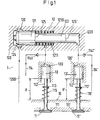
- valve 1 shows a hydraulic drive according to the invention for example for the two inlet valves 11 and 11 ' of a diesel engine.
- the two shafts 112, 112 'each have one Collar 113, or 113 ', on each of which a valve spring 115, or 115 'is supported.
- the hydraulic drive for the valves 11, 11 ' has next a synchronization piston 12 on the here as Step piston is formed.
- Each of stages 121 and 122 moves in a chamber 1210 or 1220.
- the Synchronization piston 12 is designed so that at a shift in each of the chambers 1210 and 1220 equal volume changes take place.
- the synchronization piston 121 by the valve springs 115, 115 'via the valve pistons 13, 13' and their hydraulic connection line in the direction of Starting position pushed.
- fluid loss Cold
- Damper 124 hinders hydraulic oil from flowing back into line 1200 and thus reduces the amount of reflux per unit of time.
- the damping of the impact of the synchronization piston 12 on the cylinder bottom 123 also causes the valves 11 and 11 'damped on the valve seats 111, 111' hit.
- valve pistons 13 and 13 ' are each the same are large, and the corresponding active areas 125, 125 'of the synchronization piston 12 are of the same size, then the two valve pistons 13, 13 'move at the Movement along a certain path around the same Path.
- the valve stems 112 and 112 'thus become synchronous emotional. Synchronous in the sense of the present document at the same time and in the same direction over the same distance mean.
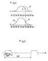
- Fig. 2 shows an example of the course of the opening and Closing a valve on a four-stroke diesel engine in Dependence on crankshaft angle.
- the valve is over opened a crankshaft angle of approximately between 180 ° and is 250 °.
- Lingers after closing the valve the valve 11, 11 'in its rest position or in Closed position R until it is opened again.
- the closing time is between 470 ° and 540 ° Crankshaft angle.
- the replenishment of hydraulic oil in the System takes place via the feed lines when the Valves 11, 11 'are in the rest position R.
- Piston pump with the line system 3 is used for the drive of the synchronization piston of the hydraulic drive from e.g. Fig. 1.
- the arrangement consists essentially of a piston pump 31 for conveying the hydraulic oil.
- the main line 32 With the One-way valve 321 for a drive, e.g. in Fig. 1 is shown.
- the bypass line 33 bridges the one-way valve 321 and opens into the cylinder chamber 310 of the piston pump 31.
- Die Bypass line 34 also bridges the one-way valve 321, but ends with both ends in the main line 32. Im Bypass 34, the switchable valve 341 is installed, which switched for example via the compressed air connection 342 becomes.
- the switchable valve 341 could also be a hydraulic, be an electromagnetic or other switchable valve.
- the bypass line 34 can be omitted if, for example the one-way valve 321 in the main line in the open state can be blocked.
- the feed line 35 is used to supply hydraulic Fluid that in the hydraulic system due to leakage is missing. It contains a one-way valve 351. Excess Hydraulic oil can flow back into the bypass 352 Feed line can be returned.
- the piston of the Piston pump 31 is e.g. with a cam (not shown) operated.
- control pressure in control line 342 is switched on. The following happens during the delivery stroke of the pump piston 311: After completion of 3512 by the piston 311, the Hydraulic fluid via paths 33, 32 34 to hydraulic drive, the valve actuation promoted. The connection 332 of the bypass 33 is later closed, the flow of hydraulic oil continues through 32 and 34.
- control pressure in control line 342 is switched off, which means that the bypass 34 is closed.
- the delivery stroke of the pump piston 311 is as follows. To Completion of 3512 by the piston 311, the Hydraulic fluid via paths 33, 32 to hydraulic drive, the valve actuation promoted. The connection 332 of the bypass 33 is later closed, the flow of hydraulic oil continues through 32.
- the closing course 42 of the valve is in FIG. 4 shown in dashed lines.
- Curve 40 in the lower diagram 4 shows the course of the stroke of piston 311 in an arrangement according to Fig. 3.
- the point 44 on the lower Curve 40 which shows the course of the movement of the piston 311 over the crank shaft angle corresponds to Position of the piston 311, where the piston 311 opens the hole 332 so that hydraulic oil flows back can.
- the hydraulic actuator 1 is for two or more valves 11, 11 'of an engine cylinder, in particular the Intake valves 11, 11 'or exhaust valves one Large diesel engine suitable.
- a hydraulic one Synchronization pistons 12, 121 have for each valve to be driven has a drive chamber 1210, 1220, which each have a valve piston 13, 13 'to be driven Valve 11, 11 'drives so that the valve piston 13, 13' move synchronously and with the same stroke.
- a Damping device 124 dampens the return of the Synchronization piston 12 in its starting position. With a hydraulic device 1 differences in Overhang H, H 'of the stems 112, 112' of the valves 11, 11 ' balanced.
Landscapes
- Engineering & Computer Science (AREA)
- Mechanical Engineering (AREA)
- General Engineering & Computer Science (AREA)
- Valve Device For Special Equipments (AREA)
Claims (10)
- Commande hydraulique (1) pour deux soupapes ou plus (11, 11') d'un cylindre de moteur, notamment des soupapes d'admission d'un grand moteur Diesel, caractérisée par un piston de synchronisation hydraulique (12, 121) qui présente pour chaque soupape à commander (11, 11') une chambre de commande (1210, 1220), qui commande respectivement un piston de soupape (13, 13') pour chaque soupape à commander (11, 11') de façon que les pistons de soupape (13, 13') se déplacent d'une manière synchronisée, et par un dispositif d'amortissement (124) pour amortir le retour du piston de synchronisation (12) et des soupapes (11, 11') dans leur position de départ, ainsi que par une installation hydraulique (1) pour égaliser des différences de dépassement (H, H') des tiges (112, 112') des deux soupapes (11, 11') ou plus commandées par la commande hydraulique (1).
- Commande hydraulique (1) selon la revendication 1, où l'installation d'amortissement pour amortir le retour di piston de synchronisation (12) présente une installation pour diminuer (124) la section transversale d'écoulement du moyen de commande hydraulique qui reflue.
- Commande hydraulique (1) selon la revendication 2, où l'installation (124) pour diminuer la section transversale d'écoulement est formée par la forme du côté d'entraínement du piston de synchronisation (121) et la paroi du cylindre de piston.
- Commande hydraulique (1) selon l'une des revendications 1 à 3, où l'installation hydraulique pour égaliser le dépassement (H, H') présente un dispositif d'alimentation (114, 114') pour le fluide hydraulique.
- Commande hydraulique (1) avec un piston de commande pour la course avant et arrière du piston de sychronisation d'une commande hydraulique selon l'une des revendications 1 à 4, avec un agencement de commutation hydraulique (3) pour retarder le retour du piston de synchronisation (12) dans sa position de départ, en comparaison avec le retour du piston de commande (311) dans sa position de départ et par conséquent du reflux du fluide hydraulique dans l'enceinte (310) dans le cylindre du piston de commande (311).
- Commande hydraulique selon l'une des revendications 1 à 5, avec une pompe à piston hydraulique pour l'entraínement du piston de synchronisation (12 ;121) et avec un système de conduits hydrauliques (32, 33, 34, 35, 352) pour amener et ramener le fluide hydraulique de la pompe à piston (31) au piston de synchronisation (12 ;121) dans le sens aller et retour,avec un conduit principal (32) comportant une soupape à une voie (321) qui empêche le reflux du fluide au cylindre de pompe (310) etavec un conduit de dérivation (34), avec une soupape (341) apte à être commutée qui passe sur la soupape à une voie (321) dans le conduit principal (32) etavec un conduit secondaire, d'amenée et de retour (33) qui passe également sur la soupape à une voie (321) dans le conduit principal (32) et qui débouche à travers la paroi de cylindre (332) de la pompe à piston hydraulique (31) dans l'enceinte de cylindre (310) de la pompe à piston (31).
- Commande hydraulique selon l'une des revendications 1 à 5, avec une pompe à piston hydraulique pour l'entraínement du piston de synchronisation (12, 121) selon l'une des revendications 1 à 5, avec un système de conduits hydrauliques (32, 33, 35, 352) pour amener et ramener le fluide hydraulique de la pompe à piston (32) au piston de synchronisation (12 ; 121) dans le sens aller et retour,avec un conduit principal (32) avec une soupape à une voie (321) qui peut être maintenue sélectivement dans la position d'ouverture et qui empêche le reflux du fluide vers le cylindre de pompe (310) à l'état non bloqué etavec un conduit secondaire, d'amenée et de retour (33) qui passe sur la soupape à une voie (321) dans le conduit principal (32) et qui débouche à travers la paroi de cylindre (332) de la pompe à piston hydraulique (31) dans l'enceinte de cylindre (310) de la pompe à piston (31).
- Commande hydraulique selon la revendication 6 ou 7, avec un agencement d'amenée (35, 352) pour du fluide hydraulique depuis et vers un réservoir, avec un conduit d'amenée (35), avec une soupape à une voie (351) qui empêche le reflux du fluide hydraulique dans le réservoir et
avec un conduit d'amenée et de retour (352) qui passe sur la soupape à une voie (351) du conduit d'amenée (35) et qui débouche au voisinage du point d'inversion inférieur dans l'enceinte de cylindre (310, 3512) de la pompe à piston (311). - Commande hydraulique selon la revendication 8, où le conduit d'amenée (35) débouche au voisinage du point d'inversion supérieur dans l'enceinte de cylindre (310),où le conduit d'amenée et de retour (352, 3512) débouche au voisinage du point d'inversion inférieur dans l'enceinte de cylindre (310) etoù le conduit secondaire, d'amenée et de reflux (33) de la commande hydraulique débouche à une hauteur qui se situe entre (332), dans l'enceinte de cylindre (310).
- Grand moteur Diesel avec une commande hydraulique (1) pour des soupapes d'admission (11, 11') ou d'échappement de cylindre selon l'une des revendications 1 à 9.
Priority Applications (8)
| Application Number | Priority Date | Filing Date | Title |
|---|---|---|---|
| EP95810620A EP0767295B1 (fr) | 1995-10-03 | 1995-10-03 | Commande de soupape hydraulique |
| DE59507966T DE59507966D1 (de) | 1995-10-03 | 1995-10-03 | Hydraulischer Ventilantrieb |
| DK95810620T DK0767295T3 (da) | 1995-10-03 | 1995-10-03 | Hydraulisk ventildrev |
| JP19920596A JP3986585B2 (ja) | 1995-10-03 | 1996-07-29 | 油圧式弁駆動装置 |
| KR1019960038663A KR100403693B1 (ko) | 1995-10-03 | 1996-09-06 | 유압밸브드라이브 |
| CN96122831A CN1088145C (zh) | 1995-10-03 | 1996-09-28 | 液压阀门驱动装置 |
| FI963945A FI107751B (fi) | 1995-10-03 | 1996-10-02 | Hydraulinen käyttölaite |
| NO19964175A NO311188B1 (no) | 1995-10-03 | 1996-10-02 | Hydraulisk ventilstyring |
Applications Claiming Priority (1)
| Application Number | Priority Date | Filing Date | Title |
|---|---|---|---|
| EP95810620A EP0767295B1 (fr) | 1995-10-03 | 1995-10-03 | Commande de soupape hydraulique |
Publications (2)
| Publication Number | Publication Date |
|---|---|
| EP0767295A1 EP0767295A1 (fr) | 1997-04-09 |
| EP0767295B1 true EP0767295B1 (fr) | 2000-03-08 |
Family
ID=8221802
Family Applications (1)
| Application Number | Title | Priority Date | Filing Date |
|---|---|---|---|
| EP95810620A Expired - Lifetime EP0767295B1 (fr) | 1995-10-03 | 1995-10-03 | Commande de soupape hydraulique |
Country Status (8)
| Country | Link |
|---|---|
| EP (1) | EP0767295B1 (fr) |
| JP (1) | JP3986585B2 (fr) |
| KR (1) | KR100403693B1 (fr) |
| CN (1) | CN1088145C (fr) |
| DE (1) | DE59507966D1 (fr) |
| DK (1) | DK0767295T3 (fr) |
| FI (1) | FI107751B (fr) |
| NO (1) | NO311188B1 (fr) |
Families Citing this family (15)
| Publication number | Priority date | Publication date | Assignee | Title |
|---|---|---|---|---|
| FR2758857A1 (fr) * | 1997-01-27 | 1998-07-31 | Aisin Seiki | Dispositif de commande de soupape pour un moteur a combustion interne |
| EP1114918B1 (fr) * | 2000-01-06 | 2004-08-11 | Wärtsilä Schweiz AG | Commande de soupape pour moteur à combustion interne et mode d'opération |
| DK176119B1 (da) * | 2000-02-16 | 2006-09-04 | Man B & W Diesel As | System til hydraulisk aktivering af en udstödsventil i en forbrændingsmotor |
| DE10124869C2 (de) * | 2001-05-22 | 2003-06-26 | Caterpillar Motoren Gmbh & Co | Hydraulische Steuereinrichtung für gleichwirkende Motorventile eines Dieselmotors |
| DE10140528A1 (de) * | 2001-08-17 | 2003-02-27 | Bosch Gmbh Robert | Vorrichtung zur Steuerung von Gaswechselventilen |
| JP2004084670A (ja) * | 2002-08-28 | 2004-03-18 | Man B & W Diesel As | 水圧で作動されるバルブ |
| DE10239747A1 (de) | 2002-08-29 | 2004-03-11 | Robert Bosch Gmbh | Hydraulischer Ventilsteller zum Betätigen eines GAswechselventils |
| CN1289796C (zh) * | 2003-10-13 | 2006-12-13 | 方戟 | 内燃式发动机的液压配气机构 |
| JP5143833B2 (ja) * | 2006-07-04 | 2013-02-13 | ルノー・トラックス | 油圧作動式弁制御システムおよびそのようなシステムを備える内燃機関 |
| US8069828B2 (en) * | 2009-08-13 | 2011-12-06 | International Engine Intellectual Property Company, Llc | Intake valve closing hydraulic adjuster |
| CN101660435B (zh) * | 2009-09-14 | 2012-10-24 | 奇瑞汽车股份有限公司 | 一种液压凸轮轴及其液压控制系统 |
| CN101936199B (zh) * | 2010-09-20 | 2012-10-03 | 武央 | 摩托车发动机液压传动配气系统 |
| SE537454C2 (sv) * | 2013-10-16 | 2015-05-05 | Freevalve Ab | Förbränningsmotor samt gashanteringssystem för pneumatisk drivning av en ventilaktuator |
| GB2552499B (en) * | 2016-07-26 | 2019-11-27 | Jaguar Land Rover Ltd | Apparatus for controlling valves using a hydraulic control system |
| GB2553120B (en) * | 2016-08-24 | 2019-12-25 | Jaguar Land Rover Ltd | Variable valve lift system with a diffusing system |
Family Cites Families (4)
| Publication number | Priority date | Publication date | Assignee | Title |
|---|---|---|---|---|
| DE3807699A1 (de) * | 1988-03-09 | 1989-09-21 | Audi Ag | Regelbare hydraulische ventilsteuerung |
| US4887562A (en) * | 1988-09-28 | 1989-12-19 | Siemens-Bendix Automotive Electronics L.P. | Modular, self-contained hydraulic valve timing systems for internal combustion engines |
| EP0520633B1 (fr) * | 1991-06-24 | 1996-08-14 | Ford Motor Company Limited | Dispositif de commande hydraulique de soupapes pour moteurs à combustion interne |
| AU9017291A (en) * | 1991-07-12 | 1993-02-11 | Caterpillar Inc. | Recuperative engine valve system and method of operation |
-
1995
- 1995-10-03 EP EP95810620A patent/EP0767295B1/fr not_active Expired - Lifetime
- 1995-10-03 DE DE59507966T patent/DE59507966D1/de not_active Expired - Lifetime
- 1995-10-03 DK DK95810620T patent/DK0767295T3/da active
-
1996
- 1996-07-29 JP JP19920596A patent/JP3986585B2/ja not_active Expired - Fee Related
- 1996-09-06 KR KR1019960038663A patent/KR100403693B1/ko not_active IP Right Cessation
- 1996-09-28 CN CN96122831A patent/CN1088145C/zh not_active Expired - Fee Related
- 1996-10-02 NO NO19964175A patent/NO311188B1/no not_active IP Right Cessation
- 1996-10-02 FI FI963945A patent/FI107751B/fi not_active IP Right Cessation
Also Published As
| Publication number | Publication date |
|---|---|
| NO964175D0 (no) | 1996-10-02 |
| FI963945A (fi) | 1997-04-04 |
| KR970021645A (ko) | 1997-05-28 |
| CN1160120A (zh) | 1997-09-24 |
| KR100403693B1 (ko) | 2004-01-28 |
| NO311188B1 (no) | 2001-10-22 |
| CN1088145C (zh) | 2002-07-24 |
| NO964175L (no) | 1997-04-04 |
| EP0767295A1 (fr) | 1997-04-09 |
| JPH09100706A (ja) | 1997-04-15 |
| DE59507966D1 (de) | 2000-04-13 |
| DK0767295T3 (da) | 2000-06-05 |
| JP3986585B2 (ja) | 2007-10-03 |
| FI963945A0 (fi) | 1996-10-02 |
| FI107751B (fi) | 2001-09-28 |
Similar Documents
| Publication | Publication Date | Title |
|---|---|---|
| EP0898650B1 (fr) | Dispositif d'injection de carburant pour moteurs a combustion interne | |
| EP0767295B1 (fr) | Commande de soupape hydraulique | |
| EP0736672B1 (fr) | Procédé de freinage moteur pour moteur à combustion interne à quatre temps | |
| DE3427092C2 (fr) | ||
| EP0455762B1 (fr) | Dispositif de commande electro-hydraulique de soupapes pour moteurs a combustion interne | |
| DE19650987A1 (de) | Bremssystem für einen Innenverbrennungsmotor | |
| EP2143896A1 (fr) | Moteur à combustion interne doté d'un dispositif de frein moteur | |
| DE3235413C2 (fr) | ||
| EP2143894B1 (fr) | Moteur à combustion interne doté d'un dispositif de frein moteur et d'un mécanisme de compensation de jeu de soupape | |
| EP2226477B1 (fr) | Unité hydraulique pour culasse de moteur à combustion interne dotée d'une commande hydraulique variable de soupape | |
| DE3714762C2 (fr) | ||
| DE102016208209A1 (de) | Hydraulische Kompressionsverstellung | |
| DE19716750A1 (de) | Kraftstoffdruckangetriebenes Motorkompressionsbremssystem | |
| DE10000750A1 (de) | Mehrzylindermotor für ein Motorrad | |
| WO1991008382A1 (fr) | Dispositif de commande hydraulique de soupape pour moteurs a combustion interne | |
| EP0455763B1 (fr) | Dispositif de commande hydraulique de soupapes pour un moteur a combustion interne multicylindre | |
| EP0282508B1 (fr) | Dispositif d'injection de carburant dans un moteur diesel avec preinjection | |
| DE4235620C2 (de) | Ventilhubverstelleinrichtung für Brennkraftmaschinen und Kompressoren | |
| EP1925812B1 (fr) | Soupape d'injection de carburant pour moteurs à combustion interne | |
| CH671809A5 (fr) | ||
| DE69330195T2 (de) | Speicherkraftstoffeinspritzvorrichtung | |
| DE4310457A1 (de) | Kraftstoffeinspritzpumpe für Brennkraftmaschinen | |
| DE4244374C2 (de) | Ventilsteuervorrichtung | |
| EP1277952B1 (fr) | Injecteur avec soupapes ouvrantes vers l'intérieur disposées l'une derrière l'autre | |
| DE10357769B4 (de) | Kraftstoffeinspritzventil |
Legal Events
| Date | Code | Title | Description |
|---|---|---|---|
| PUAI | Public reference made under article 153(3) epc to a published international application that has entered the european phase |
Free format text: ORIGINAL CODE: 0009012 |
|
| AK | Designated contracting states |
Kind code of ref document: A1 Designated state(s): DE DK FR IT NL |
|
| AX | Request for extension of the european patent |
Free format text: LT;SI |
|
| RAP1 | Party data changed (applicant data changed or rights of an application transferred) |
Owner name: WAERTSILAE NSD SCHWEIZ AG |
|
| 17P | Request for examination filed |
Effective date: 19970918 |
|
| 17Q | First examination report despatched |
Effective date: 19980507 |
|
| GRAG | Despatch of communication of intention to grant |
Free format text: ORIGINAL CODE: EPIDOS AGRA |
|
| GRAG | Despatch of communication of intention to grant |
Free format text: ORIGINAL CODE: EPIDOS AGRA |
|
| GRAH | Despatch of communication of intention to grant a patent |
Free format text: ORIGINAL CODE: EPIDOS IGRA |
|
| GRAH | Despatch of communication of intention to grant a patent |
Free format text: ORIGINAL CODE: EPIDOS IGRA |
|
| GRAA | (expected) grant |
Free format text: ORIGINAL CODE: 0009210 |
|
| AK | Designated contracting states |
Kind code of ref document: B1 Designated state(s): DE DK FR IT NL |
|
| REF | Corresponds to: |
Ref document number: 59507966 Country of ref document: DE Date of ref document: 20000413 |
|
| ITF | It: translation for a ep patent filed | ||
| ET | Fr: translation filed | ||
| REG | Reference to a national code |
Ref country code: DK Ref legal event code: T3 |
|
| PLBE | No opposition filed within time limit |
Free format text: ORIGINAL CODE: 0009261 |
|
| STAA | Information on the status of an ep patent application or granted ep patent |
Free format text: STATUS: NO OPPOSITION FILED WITHIN TIME LIMIT |
|
| 26N | No opposition filed | ||
| PGFP | Annual fee paid to national office [announced via postgrant information from national office to epo] |
Ref country code: NL Payment date: 20091016 Year of fee payment: 15 |
|
| PGFP | Annual fee paid to national office [announced via postgrant information from national office to epo] |
Ref country code: FR Payment date: 20091110 Year of fee payment: 15 |
|
| REG | Reference to a national code |
Ref country code: NL Ref legal event code: V1 Effective date: 20110501 |
|
| PG25 | Lapsed in a contracting state [announced via postgrant information from national office to epo] |
Ref country code: FR Free format text: LAPSE BECAUSE OF NON-PAYMENT OF DUE FEES Effective date: 20101102 |
|
| REG | Reference to a national code |
Ref country code: FR Ref legal event code: ST Effective date: 20110630 |
|
| PG25 | Lapsed in a contracting state [announced via postgrant information from national office to epo] |
Ref country code: NL Free format text: LAPSE BECAUSE OF NON-PAYMENT OF DUE FEES Effective date: 20110501 |
|
| PGFP | Annual fee paid to national office [announced via postgrant information from national office to epo] |
Ref country code: DK Payment date: 20131021 Year of fee payment: 19 |
|
| PGFP | Annual fee paid to national office [announced via postgrant information from national office to epo] |
Ref country code: DE Payment date: 20131021 Year of fee payment: 19 |
|
| PGFP | Annual fee paid to national office [announced via postgrant information from national office to epo] |
Ref country code: IT Payment date: 20131028 Year of fee payment: 19 |
|
| REG | Reference to a national code |
Ref country code: DE Ref legal event code: R119 Ref document number: 59507966 Country of ref document: DE |
|
| REG | Reference to a national code |
Ref country code: DK Ref legal event code: EBP Effective date: 20141031 |
|
| PG25 | Lapsed in a contracting state [announced via postgrant information from national office to epo] |
Ref country code: DE Free format text: LAPSE BECAUSE OF NON-PAYMENT OF DUE FEES Effective date: 20150501 |
|
| PG25 | Lapsed in a contracting state [announced via postgrant information from national office to epo] |
Ref country code: IT Free format text: LAPSE BECAUSE OF NON-PAYMENT OF DUE FEES Effective date: 20141003 |
|
| PG25 | Lapsed in a contracting state [announced via postgrant information from national office to epo] |
Ref country code: DK Free format text: LAPSE BECAUSE OF NON-PAYMENT OF DUE FEES Effective date: 20141031 |