EP0806339B1 - Verfahren und Vorrichtung zur sicheren Befestigung von Fahrrädern insbesondere bei deren Transport - Google Patents
Verfahren und Vorrichtung zur sicheren Befestigung von Fahrrädern insbesondere bei deren Transport Download PDFInfo
- Publication number
- EP0806339B1 EP0806339B1 EP97810283A EP97810283A EP0806339B1 EP 0806339 B1 EP0806339 B1 EP 0806339B1 EP 97810283 A EP97810283 A EP 97810283A EP 97810283 A EP97810283 A EP 97810283A EP 0806339 B1 EP0806339 B1 EP 0806339B1
- Authority
- EP
- European Patent Office
- Prior art keywords
- pedals
- bicycle
- clamping device
- bicycles
- pedal cranks
- Prior art date
- Legal status (The legal status is an assumption and is not a legal conclusion. Google has not performed a legal analysis and makes no representation as to the accuracy of the status listed.)
- Expired - Lifetime
Links
- 238000000034 method Methods 0.000 title claims abstract description 11
- 230000007246 mechanism Effects 0.000 claims abstract description 12
- 238000009434 installation Methods 0.000 description 3
- 238000006243 chemical reaction Methods 0.000 description 1
- 230000036316 preload Effects 0.000 description 1
- 230000035939 shock Effects 0.000 description 1
Images

Classifications
-
- B—PERFORMING OPERATIONS; TRANSPORTING
- B62—LAND VEHICLES FOR TRAVELLING OTHERWISE THAN ON RAILS
- B62H—CYCLE STANDS; SUPPORTS OR HOLDERS FOR PARKING OR STORING CYCLES; APPLIANCES PREVENTING OR INDICATING UNAUTHORIZED USE OR THEFT OF CYCLES; LOCKS INTEGRAL WITH CYCLES; DEVICES FOR LEARNING TO RIDE CYCLES
- B62H3/00—Separate supports or holders for parking or storing cycles
-
- B—PERFORMING OPERATIONS; TRANSPORTING
- B62—LAND VEHICLES FOR TRAVELLING OTHERWISE THAN ON RAILS
- B62H—CYCLE STANDS; SUPPORTS OR HOLDERS FOR PARKING OR STORING CYCLES; APPLIANCES PREVENTING OR INDICATING UNAUTHORIZED USE OR THEFT OF CYCLES; LOCKS INTEGRAL WITH CYCLES; DEVICES FOR LEARNING TO RIDE CYCLES
- B62H3/00—Separate supports or holders for parking or storing cycles
- B62H3/08—Separate supports or holders for parking or storing cycles involving recesses or channelled rails for embracing the bottom part of a wheel
Definitions
- the invention relates to a method and a device for the secure attachment of Bicycles, especially when transporting them with motor vehicles or trailers of all kinds. But it can also act as a reliable anti-theft device for parked bikes be used.
- the task was therefore to develop a transport device that the Pick up a whole variety of bicycles reliably and without any adjustment or conversion work can. It was also required that the device be operated by anyone without prior knowledge Can be operated very quickly and safely.
- each bike has two pedals (4a) and two extremely stable pedal cranks (4b). Below these elements are also used as an active pedaling mechanism (4). If the latter is placed on a suitable support on both sides and blocked, there is no need, apart from simply guiding the two wheels, any further Fixation of the bike.
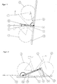
- Fig. 1 shows schematically the basic method of attachment, in the event that the Bicycle (1) is transported diagonally or even vertically.
- the clamping device (12) Before attaching the bike the clamping device (12) is pivoted into its open position. The bike is now lifted by the user and with the active pedal mechanism (4) on both sides placed on the support beam (11). Both wheels (2) and (3) are in the - for the invention no longer interested - leadership (10). The user already has both hands free for further manipulations. With the closing of the swiveling Clamping device (12), the active pedal mechanism (4) is clamped on both sides.
- the Locking (13) prevents especially strong shocks - as in Transport can occur - the unwanted opening.
- the bike With the example shown in Fig. 3 Security lock (14), the bike can be protected against theft.
- Fig. 2 shows schematically the basic method of attachment, in the event that the Bicycle is transported horizontally or almost horizontally.
- the bike (1) stands up its two wheels (2) and (3) in one - not of further interest for the invention - Leadership (10).
- To the side of this guide is the oblique support beam on both sides (11) arranged.
- the bike is placed so that its active pedaling mechanism (4) rests on both sides of the support bracket (11). With the closing of the clamping device (12) the active pedal mechanism (4) of the bicycle is clamped on both sides.
- the lock (13) prevents unwanted opening during transport. How described for Fig. 1, the bike with a security lock (14) against Theft to be protected.
- Fig. 3 shows an embodiment in which the bicycle (1) is suspended almost vertically and is attached.
- the bike is in one with both wheels (2) and (3) Leadership (10).
- the active pedal mechanism (4) lies with the pedals (4a) and / or Pedal cranks (4b) on both sides on the two adjacent support beams (11).
- the clamping device (12), the lock (13) and if used Security lock (14) are left and right of the bicycle in this embodiment available in the same version. At this point, therefore, only the in Fig. 3 front page described.
- the pivoted in the fulcrum (15) Clamping device (12) consists of the rigid part (12a) and the movable part Part (12b). The rigid part (12a) with the lock (13) on the support beam (11) hung and secured.
- the movable part (12b) by means of the spring (12c) required preload on the pedal mechanism (4) so that the bike too is kept free of play and safe against vibrations of all kinds.
- the security lock (14) With the security lock (14) the clamping device can be secured against unauthorized opening and thus protect the bike from theft.
- Fig. 4 shows an embodiment variant of Figure 3, with the difference that the Pivoting movement of one side of the clamping device (121) with the other side (12r) is rigidly coupled.
- the lock (13) and security against theft with a security lock (14) are therefore only required on one side.
- the user must be in the correct orientation when placing or inserting the bicycle of the pedal mechanism (4), but it is easier to break in, since it can also be done on the side.
Landscapes
- Engineering & Computer Science (AREA)
- Mechanical Engineering (AREA)
- Fittings On The Vehicle Exterior For Carrying Loads, And Devices For Holding Or Mounting Articles (AREA)
- Automobile Manufacture Line, Endless Track Vehicle, Trailer (AREA)
- Handcart (AREA)
- Lock And Its Accessories (AREA)
Description
- Fig. 1
- Prinzip der Befestigung in schematischer Darstellung bei einer schrägen oder sogar vertikalen Einbaulage des Fahrrades
- Fig. 2
- Prinzip der Befestigung in schematischer Darstellung bei einer horizontalen oder nahezu horizontalen Einbaulage des Fahrrades
- Fig. 3
- Ausführungsbeispiel zur Befestigung in nahezu vertikaler Einbaulage
- Fig. 4
- Ausführungsvariante zu Fig. 3
Claims (6)
- Verfahren zur sicheren Befestigung von Fahrrädern, insbesondere für deren Transport, dadurch gekennzeichnet, dass das Fahrrad an seinen beiden Pedalen (4a) oder an seinen beiden Tretkurbeln (4b) gehalten und fixiert wird.
- Verfahren nach Anspruch 1, dadurch gekennzeichnet, dass die Pedalen (4a) und die Tretkurbeln (4b) kombiniert zum Halten oder Fixieren verwendet werden.
- Verfahren nach den Ansprüchen 1 - 2, dadurch gekennzeichnet, dass diese prinzipielle Art der Halterung auch bei stationären Anwendungen für die mechanische Sicherung z.B. gegen Diebstahl verwendet wird.
- Vorrichtung zur Anwendung des Verfahrens nach mindestens einem der Ansprüche 1 - 3, dadurch gekennzeichnet, dass für die Auflage der Pedalen (4a) oder der Tretkurbeln (4b) ein geeigneter Auflageträger (11) und eine bewegliche Klemmvorrichtung (12) verwendet wird und dass mindestens ein Teil der Klemmvorrichtung gefedert ist, um die unterschiedlichen Grössen und Formen des Tretmechanismus zu überbrücken.
- Vorrichtung nach Anspruch 4, dadurch gekennzeichnet, dass die unterschiedlichen Grössen und Formen des Tretmechanismus nicht mit einer Federung, sondern mit einer Spindel oder einer anderen Schraubbewegung überbrückt werden.
- Vorrichtung nach mindestens einem der Ansprüche 4 - 5, dadurch gekennzeichnet, dass der Auflageträger (11) im unbenutzten Zustand - im Interesse des geringeren Platzbedarfes oder des kleineren Luftwiderstandes - zusammengelegt werden kann.
Applications Claiming Priority (3)
| Application Number | Priority Date | Filing Date | Title |
|---|---|---|---|
| CH1142/96 | 1996-05-06 | ||
| CH114296 | 1996-05-06 | ||
| CH114296 | 1996-05-06 |
Publications (2)
| Publication Number | Publication Date |
|---|---|
| EP0806339A1 EP0806339A1 (de) | 1997-11-12 |
| EP0806339B1 true EP0806339B1 (de) | 2001-04-04 |
Family
ID=4203477
Family Applications (1)
| Application Number | Title | Priority Date | Filing Date |
|---|---|---|---|
| EP97810283A Expired - Lifetime EP0806339B1 (de) | 1996-05-06 | 1997-05-06 | Verfahren und Vorrichtung zur sicheren Befestigung von Fahrrädern insbesondere bei deren Transport |
Country Status (3)
| Country | Link |
|---|---|
| EP (1) | EP0806339B1 (de) |
| AT (1) | ATE200259T1 (de) |
| DE (1) | DE59703266D1 (de) |
Cited By (1)
| Publication number | Priority date | Publication date | Assignee | Title |
|---|---|---|---|---|
| EP4458654A1 (de) * | 2023-05-05 | 2024-11-06 | Gasparini | Diebstahlsicherungsvorrichtung für fahrrad und klemmverfahren |
Families Citing this family (3)
| Publication number | Priority date | Publication date | Assignee | Title |
|---|---|---|---|---|
| DE19817254A1 (de) * | 1998-04-19 | 1999-10-21 | Ernst Wedekind | Automatische Abstellanlage für Zweiräder |
| CN101992816A (zh) * | 2009-08-20 | 2011-03-30 | 南通芯迎设计服务有限公司 | 一种自行车公共锁停器 |
| EP3206941A1 (de) * | 2015-02-27 | 2017-08-23 | Tommasin, Davide | Stand für ein fahrzeug mit zwei rädern und pedalen |
Family Cites Families (5)
| Publication number | Priority date | Publication date | Assignee | Title |
|---|---|---|---|---|
| US4452384A (en) * | 1983-06-06 | 1984-06-05 | Graber Joseph V | Foldable bicycle support device |
| AT380444B (de) * | 1983-12-15 | 1986-05-26 | Kunath Martin | Fahrradhalter |
| CH668400A5 (en) * | 1985-12-13 | 1988-12-30 | Alteag Fabrikations Und Handel | Stand for bicycle - has frame carrying guide tracks sloping up from frame with upper downward sloping section and holder for bicycle pedal crank arm |
| DE4314368C2 (de) * | 1992-09-11 | 1994-06-23 | Gernot Thamm | Abschließbarer Fahrradständer zur Fixierung und Sicherung eines Fahrrades |
| BE1008333A4 (nl) * | 1992-12-23 | 1996-04-02 | Godfried Struyve | Fietsstaander. |
-
1997
- 1997-05-06 AT AT97810283T patent/ATE200259T1/de not_active IP Right Cessation
- 1997-05-06 EP EP97810283A patent/EP0806339B1/de not_active Expired - Lifetime
- 1997-05-06 DE DE59703266T patent/DE59703266D1/de not_active Expired - Fee Related
Cited By (1)
| Publication number | Priority date | Publication date | Assignee | Title |
|---|---|---|---|---|
| EP4458654A1 (de) * | 2023-05-05 | 2024-11-06 | Gasparini | Diebstahlsicherungsvorrichtung für fahrrad und klemmverfahren |
Also Published As
| Publication number | Publication date |
|---|---|
| DE59703266D1 (de) | 2001-05-10 |
| ATE200259T1 (de) | 2001-04-15 |
| EP0806339A1 (de) | 1997-11-12 |
Similar Documents
| Publication | Publication Date | Title |
|---|---|---|
| DE69604626T2 (de) | Luftsack-Montagesystem | |
| EP1343662B1 (de) | Vorrichtung zur lagerung eines pedalhebels eines kraftfahrzeuges | |
| DE202008017896U1 (de) | Rollstuhlrückenlehne mit Zweipunkt-Montagebeschlagteilen | |
| DE69701033T2 (de) | Neigungs- und/oder längenverstellbare lenksäule | |
| DE102007034299A1 (de) | Tankzusammenbau für mit alternativen Kraftstoffen betriebene Fahrzeuge | |
| DE4211688C2 (de) | Halterung für Druckluftbehälter von Nutzfahrzeugen | |
| DE4403512C2 (de) | Kindersitz für Radfahrzeuge | |
| EP1251043A1 (de) | Baueinheit aus Gassackmodul und Fahrzeuglenkrad | |
| DE69109520T2 (de) | Vorrichtung für die Befestigung einer Lenksäule an den Aufbau eines Kraftfahrzeuges. | |
| DE19714356C2 (de) | Einbau-Konstruktion für Airbags im Auto | |
| DE69905676T2 (de) | Trägerkonstruktion an dem heck eines kraftfahrzeuges | |
| DE102007013602A1 (de) | Vorrichtung zur Montage eines Motors | |
| DE202017102579U1 (de) | Halterung für einen Frontalzusammenstosssensor | |
| EP0806339A1 (de) | Verfahren und Vorrichtung zur sicheren Befestigung von Fahrrädern insbesondere bei deren Transport | |
| DE69303638T3 (de) | Magnetische Befestigung eines Skihalters mit Diebstahlsicherung für Kraftfahrzeuge im allgemeinem | |
| DE102004044246A1 (de) | Lasterträger für Kraftfahrzeuge | |
| DE4400113A1 (de) | Airbagsystem für Motorfahrzeuge | |
| DE4242137A1 (de) | ||
| EP3609740B1 (de) | Vorrichtung zur halterung eines zweirads an einem strukturteil | |
| DE3116910A1 (de) | Befestigungshalter zur schraublosen befestigung von sicherheitsgurten und mit oder ohne stossmindernder bremseinrichtung | |
| DE20216345U1 (de) | Crashverriegelvorrichtung für eine Verstellvorrichtung eines Fahrzeugsitzes | |
| DE2624155A1 (de) | Diebstahlsicherung fuer sturzhelme | |
| DE19532057C2 (de) | Steckachsenhalterung für Zweiräder | |
| DE4435770C2 (de) | Vorrichtung zur Verbesserung des Insassenschutzes von Kfz.-Benutzern | |
| DE19715197A1 (de) | Vorrichtung zum Sichern von Fahrrädern |
Legal Events
| Date | Code | Title | Description |
|---|---|---|---|
| PUAI | Public reference made under article 153(3) epc to a published international application that has entered the european phase |
Free format text: ORIGINAL CODE: 0009012 |
|
| AK | Designated contracting states |
Kind code of ref document: A1 Designated state(s): AT BE CH DE ES FR GB IT LI NL |
|
| 17P | Request for examination filed |
Effective date: 19971230 |
|
| GRAG | Despatch of communication of intention to grant |
Free format text: ORIGINAL CODE: EPIDOS AGRA |
|
| 17Q | First examination report despatched |
Effective date: 20000602 |
|
| GRAG | Despatch of communication of intention to grant |
Free format text: ORIGINAL CODE: EPIDOS AGRA |
|
| GRAH | Despatch of communication of intention to grant a patent |
Free format text: ORIGINAL CODE: EPIDOS IGRA |
|
| GRAH | Despatch of communication of intention to grant a patent |
Free format text: ORIGINAL CODE: EPIDOS IGRA |
|
| GRAA | (expected) grant |
Free format text: ORIGINAL CODE: 0009210 |
|
| AK | Designated contracting states |
Kind code of ref document: B1 Designated state(s): AT BE CH DE ES FR GB IT LI NL |
|
| PG25 | Lapsed in a contracting state [announced via postgrant information from national office to epo] |
Ref country code: IT Free format text: LAPSE BECAUSE OF FAILURE TO SUBMIT A TRANSLATION OF THE DESCRIPTION OR TO PAY THE FEE WITHIN THE PRE;WARNING: LAPSES OF ITALIAN PATENTS WITH EFFECTIVE DATE BEFORE 2007 MAY HAVE OCCURRED AT ANY TIME BEFORE 2007. THE CORRECT EFFECTIVE DATE MAY BE DIFFERENT FROM THE ONE RECORDED.SCRIBED TIME-LIMIT Effective date: 20010404 Ref country code: GB Free format text: LAPSE BECAUSE OF FAILURE TO SUBMIT A TRANSLATION OF THE DESCRIPTION OR TO PAY THE FEE WITHIN THE PRESCRIBED TIME-LIMIT Effective date: 20010404 |
|
| REF | Corresponds to: |
Ref document number: 200259 Country of ref document: AT Date of ref document: 20010415 Kind code of ref document: T |
|
| REG | Reference to a national code |
Ref country code: CH Ref legal event code: EP |
|
| PG25 | Lapsed in a contracting state [announced via postgrant information from national office to epo] |
Ref country code: AT Free format text: LAPSE BECAUSE OF NON-PAYMENT OF DUE FEES Effective date: 20010506 |
|
| REF | Corresponds to: |
Ref document number: 59703266 Country of ref document: DE Date of ref document: 20010510 |
|
| REG | Reference to a national code |
Ref country code: CH Ref legal event code: NV Representative=s name: BOVARD AG PATENTANWAELTE |
|
| PG25 | Lapsed in a contracting state [announced via postgrant information from national office to epo] |
Ref country code: BE Free format text: LAPSE BECAUSE OF NON-PAYMENT OF DUE FEES Effective date: 20010531 |
|
| ET | Fr: translation filed | ||
| GBV | Gb: ep patent (uk) treated as always having been void in accordance with gb section 77(7)/1977 [no translation filed] |
Effective date: 20010404 |
|
| PG25 | Lapsed in a contracting state [announced via postgrant information from national office to epo] |
Ref country code: ES Free format text: LAPSE BECAUSE OF FAILURE TO SUBMIT A TRANSLATION OF THE DESCRIPTION OR TO PAY THE FEE WITHIN THE PRESCRIBED TIME-LIMIT Effective date: 20011030 |
|
| BERE | Be: lapsed |
Owner name: ZBINDEN HUGO Effective date: 20010531 |
|
| PLBE | No opposition filed within time limit |
Free format text: ORIGINAL CODE: 0009261 |
|
| STAA | Information on the status of an ep patent application or granted ep patent |
Free format text: STATUS: NO OPPOSITION FILED WITHIN TIME LIMIT |
|
| 26N | No opposition filed | ||
| PGFP | Annual fee paid to national office [announced via postgrant information from national office to epo] |
Ref country code: FR Payment date: 20020513 Year of fee payment: 6 |
|
| PGFP | Annual fee paid to national office [announced via postgrant information from national office to epo] |
Ref country code: NL Payment date: 20030425 Year of fee payment: 7 |
|
| PGFP | Annual fee paid to national office [announced via postgrant information from national office to epo] |
Ref country code: DE Payment date: 20030428 Year of fee payment: 7 |
|
| PG25 | Lapsed in a contracting state [announced via postgrant information from national office to epo] |
Ref country code: FR Free format text: LAPSE BECAUSE OF NON-PAYMENT OF DUE FEES Effective date: 20040130 |
|
| REG | Reference to a national code |
Ref country code: FR Ref legal event code: ST |
|
| PG25 | Lapsed in a contracting state [announced via postgrant information from national office to epo] |
Ref country code: NL Free format text: LAPSE BECAUSE OF NON-PAYMENT OF DUE FEES Effective date: 20041201 Ref country code: DE Free format text: LAPSE BECAUSE OF NON-PAYMENT OF DUE FEES Effective date: 20041201 |
|
| NLV4 | Nl: lapsed or anulled due to non-payment of the annual fee |
Effective date: 20041201 |
|
| PGFP | Annual fee paid to national office [announced via postgrant information from national office to epo] |
Ref country code: CH Payment date: 20060508 Year of fee payment: 10 |
|
| REG | Reference to a national code |
Ref country code: CH Ref legal event code: PL |
|
| PG25 | Lapsed in a contracting state [announced via postgrant information from national office to epo] |
Ref country code: CH Free format text: LAPSE BECAUSE OF NON-PAYMENT OF DUE FEES Effective date: 20070531 Ref country code: LI Free format text: LAPSE BECAUSE OF NON-PAYMENT OF DUE FEES Effective date: 20070531 |