EP0806021B1 - Vorrichtung und verfahren zur bestimmung der steifigkeit von blattgut, wie z.b. banknoten - Google Patents
Vorrichtung und verfahren zur bestimmung der steifigkeit von blattgut, wie z.b. banknoten Download PDFInfo
- Publication number
- EP0806021B1 EP0806021B1 EP96939908A EP96939908A EP0806021B1 EP 0806021 B1 EP0806021 B1 EP 0806021B1 EP 96939908 A EP96939908 A EP 96939908A EP 96939908 A EP96939908 A EP 96939908A EP 0806021 B1 EP0806021 B1 EP 0806021B1
- Authority
- EP
- European Patent Office
- Prior art keywords
- sheet material
- sounds
- mechanical means
- transport
- stiffness
- Prior art date
- Legal status (The legal status is an assumption and is not a legal conclusion. Google has not performed a legal analysis and makes no representation as to the accuracy of the status listed.)
- Expired - Lifetime
Links
- 238000000034 method Methods 0.000 title claims description 7
- 230000000737 periodic effect Effects 0.000 claims description 2
- 238000005452 bending Methods 0.000 claims 1
- 238000010586 diagram Methods 0.000 description 11
- 230000002093 peripheral effect Effects 0.000 description 3
- 241001295925 Gegenes Species 0.000 description 2
- 230000001419 dependent effect Effects 0.000 description 2
- 238000011156 evaluation Methods 0.000 description 2
- 238000005259 measurement Methods 0.000 description 2
- 230000005540 biological transmission Effects 0.000 description 1
- 208000027744 congestion Diseases 0.000 description 1
- 238000011161 development Methods 0.000 description 1
- 230000003993 interaction Effects 0.000 description 1
- 238000005457 optimization Methods 0.000 description 1
- 230000010355 oscillation Effects 0.000 description 1
- 238000012545 processing Methods 0.000 description 1
Images


Classifications
-
- G—PHYSICS
- G01—MEASURING; TESTING
- G01N—INVESTIGATING OR ANALYSING MATERIALS BY DETERMINING THEIR CHEMICAL OR PHYSICAL PROPERTIES
- G01N3/00—Investigating strength properties of solid materials by application of mechanical stress
- G01N3/32—Investigating strength properties of solid materials by application of mechanical stress by applying repeated or pulsating forces
- G01N3/34—Investigating strength properties of solid materials by application of mechanical stress by applying repeated or pulsating forces generated by mechanical means, e.g. hammer blows
-
- G—PHYSICS
- G01—MEASURING; TESTING
- G01N—INVESTIGATING OR ANALYSING MATERIALS BY DETERMINING THEIR CHEMICAL OR PHYSICAL PROPERTIES
- G01N29/00—Investigating or analysing materials by the use of ultrasonic, sonic or infrasonic waves; Visualisation of the interior of objects by transmitting ultrasonic or sonic waves through the object
- G01N29/14—Investigating or analysing materials by the use of ultrasonic, sonic or infrasonic waves; Visualisation of the interior of objects by transmitting ultrasonic or sonic waves through the object using acoustic emission techniques
-
- G—PHYSICS
- G01—MEASURING; TESTING
- G01N—INVESTIGATING OR ANALYSING MATERIALS BY DETERMINING THEIR CHEMICAL OR PHYSICAL PROPERTIES
- G01N29/00—Investigating or analysing materials by the use of ultrasonic, sonic or infrasonic waves; Visualisation of the interior of objects by transmitting ultrasonic or sonic waves through the object
- G01N29/22—Details, e.g. general constructional or apparatus details
- G01N29/225—Supports, positioning or alignment in moving situation
-
- G—PHYSICS
- G01—MEASURING; TESTING
- G01N—INVESTIGATING OR ANALYSING MATERIALS BY DETERMINING THEIR CHEMICAL OR PHYSICAL PROPERTIES
- G01N33/00—Investigating or analysing materials by specific methods not covered by groups G01N1/00 - G01N31/00
- G01N33/34—Paper
- G01N33/346—Paper sheets
-
- G—PHYSICS
- G07—CHECKING-DEVICES
- G07D—HANDLING OF COINS OR VALUABLE PAPERS, e.g. TESTING, SORTING BY DENOMINATIONS, COUNTING, DISPENSING, CHANGING OR DEPOSITING
- G07D7/00—Testing specially adapted to determine the identity or genuineness of valuable papers or for segregating those which are unacceptable, e.g. banknotes that are alien to a currency
- G07D7/181—Testing mechanical properties or condition, e.g. wear or tear
- G07D7/182—Testing stiffness
-
- G—PHYSICS
- G01—MEASURING; TESTING
- G01N—INVESTIGATING OR ANALYSING MATERIALS BY DETERMINING THEIR CHEMICAL OR PHYSICAL PROPERTIES
- G01N2203/00—Investigating strength properties of solid materials by application of mechanical stress
- G01N2203/0014—Type of force applied
- G01N2203/0023—Bending
-
- G—PHYSICS
- G01—MEASURING; TESTING
- G01N—INVESTIGATING OR ANALYSING MATERIALS BY DETERMINING THEIR CHEMICAL OR PHYSICAL PROPERTIES
- G01N2203/00—Investigating strength properties of solid materials by application of mechanical stress
- G01N2203/003—Generation of the force
- G01N2203/005—Electromagnetic means
- G01N2203/0051—Piezoelectric means
-
- G—PHYSICS
- G01—MEASURING; TESTING
- G01N—INVESTIGATING OR ANALYSING MATERIALS BY DETERMINING THEIR CHEMICAL OR PHYSICAL PROPERTIES
- G01N2291/00—Indexing codes associated with group G01N29/00
- G01N2291/02—Indexing codes associated with the analysed material
- G01N2291/023—Solids
- G01N2291/0237—Thin materials, e.g. paper, membranes, thin films
Definitions
- the invention relates to a device and a method for determination the rigidity of sheet material, such as. B. banknotes. .
- Such a device is known from EP-A-00 73 133 and US-A-4 519 249. With this device the sheet material is guided between two flat belts in the middle and redirected by a double conical roller through an angle of 180 °. A deformation occurs in the longitudinal and transverse directions at the same time of the sheet material instead. The noises generated during this process are detected by a microphone. Determined from the detected noises then an evaluation device the rigidity of the sheet material.
- a disadvantage of the device is that the noise generated decrease significantly if the stiffness of a sheet is measured several times.
- the rigidity of the sheet material is with each measurement by the Measurement associated deformation less.
- the object of the invention is a device or to propose a method for determining the stiffness of sheet material, where the stiffness of the foliage is essentially unchanged remains.
- the basic idea of the invention is essentially to generate to provide mechanical means of noise, which the sheet material periodically touch and stimulate it to vibrate. The through the Noise generated vibrations are then detected by a detector. An evaluation device then determines from the detected noises the rigidity of the leaf material. Because the volume of the generated noise is approximately proportional to the stiffness of the leaf material, the volume of the generated noise is a direct measure of rigidity of the leaf material.
- the sheet material is held or guided in a transport device in such a way that it is in the area of touch within certain limits of mechanical Can give in to action without being irreversibly deformed.
- An advantage of the invention is that the rigidity of the sheet material is almost remains unchanged. Even with multiple stiffness determinations the intensity of the noise generated remains essentially the same equal. The reproducibility of the intensity of the noise generated is on average at least 95%.
- the mechanical Middle a rotating roller with a certain number of corners on.
- the corners are arranged rotationally symmetrically on the roller.
- the Sheet material is transported through the device by a transport device and the drive axis of the rotating roller perpendicular to the transport direction of the leaf material arranged.
- the direction of rotation of the rotating The roller is directed in the direction of transport.
- the rotational frequency of the rotating roller is chosen so that the frequency of rotation and Radius of the roller-dependent peripheral speed is greater than or equal to is the transport speed of the sheet material.
- Fig. 1 shows a schematic diagram of a preferred embodiment of the Invention in a side view.
- the sheet material 10 is, for example, by means of Transport belts, which are not shown here for reasons of clarity are in the direction of transport T through the device transported.
- a rotating roller 30 with six rotationally symmetrically arranged Shown corners.
- the drive axis 31 of the rotating roller 30 is vertical aligned with the transport direction T of the sheet material.
- the direction of rotation of the roller 30 is in the direction of the transport direction T des Sheets directed.
- the rotational frequency of the roller 30 is chosen so that the peripheral speed dependent on the rotational frequency and the radius of the roller 30 the roller 30 is greater than or equal to the transport speed of the leaf matter is.
- the roller 30 Due to the rotation of the roller 30, the corners periodically touch the sheet material 10 and thus stimulate it to vibrate.
- the sheet material is in the area the roller 30 is raised by a lifting height H.
- the lifting height H is a measure for the volume of the generated noise.
- the radius of the roller 30, the number N of corners and the rotational frequency the roller 30 are the parameters by means of which the preferred embodiment the invention optimally to the respective apparatus boundary conditions, such as. the maximum spatial extent of the device adjusted can be.
- the frequency of contact of the roller on the sheet material 10 results from the product of the rotational frequency and the number of corners.
- the lifting height H depends on the choice of the radius of the roller and the number of corners.
- FIGS. 2 and 3 show the preferred embodiment with a Transport device seen in a side view and from below, wherein the transport device is integrated in the hexagonal roller 30.
- the Transport device has three upper transport belts 11 and two lower Transport belt 12, between which the sheet material 10 for transport is jammed by the device.
- roller free-running rollers 32, 33 are provided, via which the corresponding Transport belts are guided. These roles can be from Decouple drive axle 31, for example, by means of corresponding ball bearings, so that the conveyor belts 11 and 12 regardless of the peripheral speed the roller 30 moves at a constant transport speed can be.
- the radius of the idler rollers 32 is preferred chosen equal to the radius of the incircle of the roller 30.
- the radius of the free-running rollers 33 is preferably smaller than the radius of the incircle the hexagonal roller 30 selected.
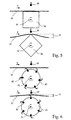
- FIG. 5 shows a variation of the preferred embodiment with a square roller 34.
- the lifting height H of the square roller 34 is greater than the lifting height H of the hexagonal roller 30. If the other parameters are constant the noise generated by the square roller 34 is thus louder than that from the hexagonal roller 30.
- the Frequency of rotation of the square roller 34 with respect to the hexagonal roller 30 be increased accordingly.
- the rotational frequency can be based on of the mechanical problems occurring at high rotational frequencies only in certain limits vary, so that an optimization of the parameters is necessary becomes sufficient at a given touch frequency to make loud noises.
- FIG. 6 shows a second embodiment of the invention, in which 40 brushes 41 are arranged rotationally symmetrically on a rotating roller.
- these brushes 41 are each designed to be movable on their own axis, so that the brushes 41 fold outwards due to the centrifugal force generated during the rotation of the roller 40.
- the noises necessary to determine the rigidity of the sheet material are generated here by periodically touching the brushes 41 against the sheet material 10.
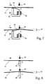
- the device for generating noise as a mechanical means has an electromagnet 50 with a yoke 51, a coil 52 and a movable tongue 53.
- the movable tongue 53 is vibrated.
- the noises are generated by periodically touching the sheet material 10 through the tongue 53.
- the oscillation frequency of the movable tongue 53 corresponds to the frequency of the AC voltage applied.
- the stroke height H can be changed by the maximum voltage difference of the AC voltage.
- Fig. 8 shows a fourth embodiment of the invention, in which the mechanical A piezo element 60 has means for generating noise.
- the spatial expansion of the piezo element 60 changed in the direction perpendicular to the sheet material plane become.
- the frequency of the expansion of the piezo element 60 corresponds the frequency of the AC voltage applied.
- the degree of expansion of the piezo element 60 depends on the maximum voltage difference the AC voltage, but is relatively low. This just leads to a low lifting height H of the sheet material 10 and thus also to a low one Volume of the generated noise.
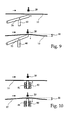
- FIG. 9 A method for increasing the lifting height H of the sheet material 10 is shown in FIG. 9 shown. It is to provide an additional lever system 70 that is connected to the piezo element 60 and by means of which the expansion of the piezo element 60 is amplified so that a desired lifting height H is achieved.
- bimorph piezo elements 60 are used to increase the lifting height H of the sheet material 10.
- bimorphic piezo elements 60 are at least two piezo elements 60 in a tight bond with each other and the expansion of the Piezo elements 60 are converted into a bend in the piezo elements 60.
- These bimorphic piezo elements 60 allow lifting heights H of several Generate millimeters.
- Fig. 10 shows a fifth embodiment of the invention, in which the mechanical Means for generating the noise a coil 80 with a have movable magnetic core 81. If you put one on the coil AC voltage, the movable magnetic core 81 vibrates with the Frequency of the AC voltage. The noises are caused by periodic Touching the sheet material 10 by the magnetic core 81. The deflection of the movable core 81 and thus the lifting height H of the sheet material 10 can be influenced by the maximum voltage difference of the AC voltage become.
Landscapes
- Physics & Mathematics (AREA)
- Chemical & Material Sciences (AREA)
- General Physics & Mathematics (AREA)
- Health & Medical Sciences (AREA)
- Life Sciences & Earth Sciences (AREA)
- Pathology (AREA)
- Analytical Chemistry (AREA)
- Biochemistry (AREA)
- General Health & Medical Sciences (AREA)
- Immunology (AREA)
- Food Science & Technology (AREA)
- Engineering & Computer Science (AREA)
- Acoustics & Sound (AREA)
- Medicinal Chemistry (AREA)
- Investigating Strength Of Materials By Application Of Mechanical Stress (AREA)
- Delivering By Means Of Belts And Rollers (AREA)
- Inspection Of Paper Currency And Valuable Securities (AREA)
- Investigating Or Analyzing Materials By The Use Of Ultrasonic Waves (AREA)
- Credit Cards Or The Like (AREA)
- Treatment Of Fiber Materials (AREA)
Description
- Fig. 1
- Prinzipskizze einer bevorzugten Ausführungsform,
- Fig. 2
- Prinzipskizze der bevorzugte Ausführungsform mit Transportriemen,
- Fig. 3
- Prinzipskizze von unten gegen die bevorzugte Ausführungsform mit Transportriemen,
- Fig. 4
- Prinzipskizze von unten gegen die bevorzugte Ausführungsform mit Transportriemen und Leitplatte,
- Fig. 5
- Prinzipskizze einer Variation der bevorzugten Ausführungsform,
- Fig. 6
- Prinzipskizze einer zweiten Ausführungsform der Erfindung,
- Fig. 7
- Prinzipskizze einer dritten Ausführungsform der Erfindung,
- Fig. 8
- Prinzipskizze einer vierten Ausführungsform der Erfindung,
- Fig. 9
- Prinzipskizze einer Weiterbildung der vierten Ausführungsform der Erfindung,
- Fig. 10
- Prinzipskizze einer fünften Ausführungsform der Erfindung.
Die Fig. 7 zeigt eine dritte Ausführungsform der Erfindung, bei der die Einrichtung zur Erzeugung von Geräuschen als mechanisches Mittel einen Elektromagneten 50 mit einem Joch 51, einer Spule 52 und einer beweglichen Zunge 53 aufweist. Durch Anlegen einer Wechselspannung an die Spule 50 wird die bewegliche Zunge 53 in Schwingungen versetzt. Die Geräusche werden durch periodisches Berühren des Blattguts 10 durch die Zunge 53 erzeugt. Die Schwingungsfrequenz der beweglichen Zunge 53 entspricht dabei der Frequenz der angelegten Wechselspannung. Die Hubhöhe H kann durch die maximale Spannungsdifferenz der Wechselspannung verändert werden.
Claims (13)
- Vorrichtung zur Bestimmung der Steifigkeit von Blattgut, wie z. B. Banknoten, mitdadurch gekennzeichnet, daß die Einrichtung zur Erzeugung von Geräuschen mechanische Mittel (30, 34, 40, 41, 50, 60, 70, 80, 81) aufweist, die das Blattgut (10) periodisch berühren und es so zu Schwingungen anregen.einer Einrichtung zur Erzeugung von Geräuschen unter Verwendung des Blattguts,einem Detektor zur Detektion der erzeugten Geräusche,einer Auswerteeinrichtung, die aus den detektierten Geräuschen die Steifigkeit des Blattguts bestimmt,
- Vorrichtung nach Anspruch 1, dadurch gekennzeichnet, daß die mechanischen Mittel eine rotierende Walze (30, 34) mit einer bestimmten Anzahl (N) von rotationssymmetrisch angeordneten Ecken aufweisen.
- Vorrichtung nach Anspruch 1, dadurch gekennzeichnet, daß die mechanischen Mittel eine rotierende Walze (40) aufweisen, an der rotationssymrnetrisch Bürsten (41) angeordnet sind.
- Vorrichtung nach Anspruch 2 oder 3, dadurch gekennzeichnet, daß das Blattgut mittels einer Transporteinrichtung (11,12) durch die Vorrichtung transportiert wird und die Antriebsachse (31) der rotierenden Walze (30, 34, 40) senkrecht zur Transportrichtung (T) des Blattguts angeordnet ist.
- Vorrichtung nach Anspruch 4, dadurch gekennzeichnet, daß die Umfangsgeschwindigkeit der Walze (30, 34, 40) in Richtung der Transportrichtung (T) des Blattguts gerichtet und größer oder gleich der Transportgeschwindigkeit des Blattguts ist.
- Vorrichtung nach Anspruch 4, dadurch gekennzeichnet, daß die Transporteinrichtung obere und/oder untere Transportriemen (11,12) aufweist, die durch freilaufende Rollen (32, 33) von der Antriebsachse (31) entkoppelt sind.
- Vorrichtung nach Anspruch 6, dadurch gekennzeichnet, daß die Transporteinrichtung eine Leitplatte (13) mit einer Aussparung (14) aufweist, durch die die Walze (30, 34, 40) in Kontakt mit dem Blattgut (10) tritt.
- Vorrichtung nach Anspruch 1, dadurch gekennzeichnet, daß die mechanischen Mittel einen Elektromagneten (50) mit einer beweglichen Zunge (53) aufweisen.
- Vorrichtung nach Anspruch 1, dadurch gekennzeichnet, daß die mechanischen Mittel ein Piezoelement (60) aufweisen.
- Vorrichtung nach Anspruch 9, dadurch gekennzeichnet, daß die mechanischen Mittel ein zusätzliches Hebelsystem (70) aufweisen, das mit dem Piezoelement (60) verbunden ist.
- Vorrichtung nach Anspruch 9, dadurch gekennzeichnet, daß die mechanischen Mittel mindestens ein weiteres Piezoelement (60) aufweisen und daß die Piezoelemente (60) in einem festen Verbund miteinander stehen, so daß die Ausdehnung der Piezoelemente (60) in eine Biegung der Piezoelemente umgesetzt wird.
- Vorrichtung nach Anspruch 1, dadurch gekennzeichnet, daß die mechanischen Mittel eine Spule (80) mit einem magnetischen Kern (81) aufweisen.
- Verfahren zur Bestimmung der Steifigkeit von Blattgut, wie z. B. Banknoten, bei demdadurch gekennzeichnet, daß zur Erzeugung der Geräusche, das Blattgut (10) durch periodisches Berühren des Blattguts (10) zu Schwingungen angeregt wird.unter Verwendung des Blattguts Geräusche erzeugt werden,die erzeugten Geräusche des Blattguts detektiert werden undaus den detektierten Geräuschen des Blattguts die Steifigkeit des Blattguts bestimmt wird
Applications Claiming Priority (3)
| Application Number | Priority Date | Filing Date | Title |
|---|---|---|---|
| DE19543674A DE19543674A1 (de) | 1995-11-23 | 1995-11-23 | Vorrichtung und Verfahren zur Bestimmung der Steifigkeit von Blattgut, wie z. B. Banknoten |
| DE19543674 | 1995-11-23 | ||
| PCT/EP1996/005175 WO1997019425A1 (de) | 1995-11-23 | 1996-11-22 | Vorrichtung und verfahren zur bestimmung der steifigkeit von blattgut, wie z.b. banknoten |
Publications (2)
| Publication Number | Publication Date |
|---|---|
| EP0806021A1 EP0806021A1 (de) | 1997-11-12 |
| EP0806021B1 true EP0806021B1 (de) | 2001-01-24 |
Family
ID=7778220
Family Applications (1)
| Application Number | Title | Priority Date | Filing Date |
|---|---|---|---|
| EP96939908A Expired - Lifetime EP0806021B1 (de) | 1995-11-23 | 1996-11-22 | Vorrichtung und verfahren zur bestimmung der steifigkeit von blattgut, wie z.b. banknoten |
Country Status (13)
| Country | Link |
|---|---|
| US (1) | US6026681A (de) |
| EP (1) | EP0806021B1 (de) |
| JP (1) | JP2001506740A (de) |
| CN (1) | CN1075213C (de) |
| AT (1) | ATE198945T1 (de) |
| AU (1) | AU7696996A (de) |
| DE (2) | DE19543674A1 (de) |
| DK (1) | DK0806021T3 (de) |
| EA (1) | EA000237B1 (de) |
| ES (1) | ES2153603T3 (de) |
| GR (1) | GR3035731T3 (de) |
| PT (1) | PT806021E (de) |
| WO (1) | WO1997019425A1 (de) |
Families Citing this family (21)
| Publication number | Priority date | Publication date | Assignee | Title |
|---|---|---|---|---|
| GB9710719D0 (en) * | 1997-05-24 | 1997-07-16 | Ncr Int Inc | A system for authenticating printed documents |
| US6186659B1 (en) * | 1998-08-21 | 2001-02-13 | Agilent Technologies Inc. | Apparatus and method for mixing a film of fluid |
| GB0111586D0 (en) * | 2001-05-11 | 2001-07-04 | Rue De Int Ltd | Sheet handling apparatus |
| US7426062B2 (en) * | 2001-08-21 | 2008-09-16 | Canon Kabushiki Kaisha | Signal output apparatus, image forming apparatus and information output apparatus |
| JP3673777B2 (ja) * | 2001-08-21 | 2005-07-20 | キヤノン株式会社 | 信号出力装置、シート材の種類判別装置及び画像形成装置 |
| DE10141375C1 (de) | 2001-08-23 | 2003-03-13 | Siemens Dematic Ag | Vorrichtung zum Trennen von Sendungen in Dickenklassen |
| US6913260B2 (en) * | 2002-03-06 | 2005-07-05 | Cummins-Allison Corp. | Currency processing system with fitness detection |
| JP4143602B2 (ja) * | 2002-06-04 | 2008-09-03 | キヤノン株式会社 | 重送検知方法、重送検知装置、画像形成装置及び画像読取装置 |
| JP2006500594A (ja) * | 2002-09-27 | 2006-01-05 | シーメンス アクチエンゲゼルシヤフト | 扁平な送付物の曲げ強さの測定装置 |
| JP2004161444A (ja) * | 2002-11-14 | 2004-06-10 | Canon Inc | シート材判別装置 |
| JP3658392B2 (ja) * | 2002-12-27 | 2005-06-08 | キヤノン電子株式会社 | 信号出力装置及び信号出力装置を備えたシート材処理装置 |
| JP4143417B2 (ja) * | 2003-01-06 | 2008-09-03 | キヤノン株式会社 | シート材判別方法、シート材判別装置及び画像形成装置 |
| DE10318104A1 (de) * | 2003-04-22 | 2004-11-11 | Giesecke & Devrient Gmbh | Verfahren und Vorrichtung zur Bestimmung der Lappigkeit von Blattgut |
| US7315007B2 (en) * | 2003-06-09 | 2008-01-01 | Siemens Dematic Corp. | Method and apparatus for stiffness and thickness detection in mail sorting systems |
| DE102006007678A1 (de) | 2006-02-15 | 2007-08-16 | Grüner, Alexander | Verfahren und Vorrichtung zur Bestimmung der Weichheit von Hygienepapieren und Textilien |
| JP2007322558A (ja) | 2006-05-30 | 2007-12-13 | Canon Inc | 水分量推定装置、シート材処理装置、水分量推定方法、及びシート材処理方法 |
| FR2901885B1 (fr) * | 2006-05-31 | 2008-08-08 | Georgia Pacific France Soc Par | Procede et dispositif de mesure de la rigidite d'un echantillon de papier |
| US9395277B2 (en) * | 2011-12-06 | 2016-07-19 | Kodak Alaris Inc. | Self-adjusting audio detection of medium jam |
| JP6679824B2 (ja) | 2014-09-16 | 2020-04-15 | 横浜ゴム株式会社 | 衝撃試験装置および方法 |
| WO2016052613A1 (ja) * | 2014-10-03 | 2016-04-07 | 三菱電機株式会社 | 画像読取装置 |
| JP6503694B2 (ja) * | 2014-11-06 | 2019-04-24 | 横浜ゴム株式会社 | 衝撃試験装置および方法 |
Family Cites Families (11)
| Publication number | Priority date | Publication date | Assignee | Title |
|---|---|---|---|---|
| CH544026A (de) * | 1972-09-21 | 1973-11-15 | Grapha Holding Ag | Vorrichtung zum Umsetzen eines Papierbogenstapels in einen Schuppenstrom |
| FR2309851A1 (fr) * | 1975-05-02 | 1976-11-26 | Gueugnon Forges | Procede et appareil de mesure de contrainte dans une bande soumise a une traction et leurs applications, notamment pour la mesure de l'etat de planeite d'une telle bande |
| DE3048710A1 (de) * | 1980-12-23 | 1982-07-15 | GAO Gesellschaft für Automation und Organisation mbH, 8000 München | "verfahren zur pruefung des flaechengewichts von duennem material" |
| ATE18705T1 (de) * | 1981-08-20 | 1986-04-15 | De La Rue Syst | Geraet zur feststellung des zustandes eines blattes. |
| EP0098115A1 (de) * | 1982-06-28 | 1984-01-11 | De La Rue Systems Limited | Vorrichtung zur Ermittlung der Beschaffenheit eines Blattes oder eines Gewebes |
| JP2647449B2 (ja) * | 1988-08-31 | 1997-08-27 | グローリー工業株式会社 | 紙葉類の性状検知装置 |
| US5089776A (en) * | 1989-09-25 | 1992-02-18 | Nkk Corporation | Apparatus for detecting defects in a moving steel strip with a magnetizing yoke and a sensor placed on opposite sides of the strip |
| IE914335A1 (en) * | 1990-12-21 | 1992-07-01 | Measurex Corp | A sensor, system and method for determining z-directional¹properties of a sheet |
| GB9114469D0 (en) * | 1991-07-04 | 1991-08-21 | Ncr Co | Apparatus for testing the stiffness of a sheet |
| DE4426405C1 (de) * | 1994-07-26 | 1995-08-31 | Freudenberg Carl Fa | Vorrichtung und Verfahren zur Messung der Reißfestigkeit von textilen Flächengebilden |
| SE504576C2 (sv) * | 1994-10-06 | 1997-03-10 | Lorentzen & Wettre Ab | Anordning för att med ultraljud mäta de elastiska egenskaperna hos en pappersbana i rörelse |
-
1995
- 1995-11-23 DE DE19543674A patent/DE19543674A1/de not_active Withdrawn
-
1996
- 1996-11-22 AU AU76969/96A patent/AU7696996A/en not_active Abandoned
- 1996-11-22 EP EP96939908A patent/EP0806021B1/de not_active Expired - Lifetime
- 1996-11-22 DE DE59606385T patent/DE59606385D1/de not_active Expired - Fee Related
- 1996-11-22 JP JP53282696A patent/JP2001506740A/ja active Pending
- 1996-11-22 EA EA199700132A patent/EA000237B1/ru not_active IP Right Cessation
- 1996-11-22 WO PCT/EP1996/005175 patent/WO1997019425A1/de not_active Ceased
- 1996-11-22 US US08/875,105 patent/US6026681A/en not_active Expired - Fee Related
- 1996-11-22 DK DK96939908T patent/DK0806021T3/da active
- 1996-11-22 CN CN96192346A patent/CN1075213C/zh not_active Expired - Fee Related
- 1996-11-22 PT PT96939908T patent/PT806021E/pt unknown
- 1996-11-22 AT AT96939908T patent/ATE198945T1/de not_active IP Right Cessation
- 1996-11-22 ES ES96939908T patent/ES2153603T3/es not_active Expired - Lifetime
-
2001
- 2001-04-06 GR GR20010400583T patent/GR3035731T3/el not_active IP Right Cessation
Also Published As
| Publication number | Publication date |
|---|---|
| DE59606385D1 (de) | 2001-03-01 |
| EP0806021A1 (de) | 1997-11-12 |
| PT806021E (pt) | 2001-05-31 |
| AU7696996A (en) | 1997-06-11 |
| EA199700132A1 (ru) | 1997-12-30 |
| EA000237B1 (ru) | 1999-02-25 |
| JP2001506740A (ja) | 2001-05-22 |
| DE19543674A1 (de) | 1997-05-28 |
| GR3035731T3 (en) | 2001-07-31 |
| WO1997019425A1 (de) | 1997-05-29 |
| ATE198945T1 (de) | 2001-02-15 |
| CN1177410A (zh) | 1998-03-25 |
| CN1075213C (zh) | 2001-11-21 |
| US6026681A (en) | 2000-02-22 |
| DK0806021T3 (da) | 2001-02-05 |
| ES2153603T3 (es) | 2001-03-01 |
Similar Documents
| Publication | Publication Date | Title |
|---|---|---|
| EP0806021B1 (de) | Vorrichtung und verfahren zur bestimmung der steifigkeit von blattgut, wie z.b. banknoten | |
| DE2630228C3 (de) | ||
| DE69207286T2 (de) | Vorrichtung zum Testen der Steifheit eines Blattes | |
| DE2606149A1 (de) | Messungs- und registrierverfahren der wellenfoermigen durchbiegungen der rollbahn einer verlegten schiene und vorrichtung zur ausuebung dieses verfahrens | |
| DE68913628T2 (de) | Vorrichtung zum Prüfen von Eigenschaften von Papierbögen oder dergleichen. | |
| DE2617192C3 (de) | Vorrichtung zur Messung vertikaler, wellenförmiger Abnützungserscheinungen von Eisenbahngleisen | |
| EP0467117B1 (de) | Vorrichtung zum Messen der Dicke und/oder der Ungleichmässigkeit von Vliesen oder Watten an Spinnereivorbereitungsmaschinen | |
| EP2304699B1 (de) | Verfahren und vorrichtung zum bearbeiten von wertdokumenten | |
| DE3122490C2 (de) | Magnetische Prüfeinrichtung zur Echtheitsprüfung von mit einem magnetischen Muster versehenen Banknoten | |
| DE2813887C2 (de) | Verfahren und Vorrichtung zum Konstanthalten der Spannung eines Vorgarns zwischen dem Streckwerk und dem Oberteil einer voreilend angetriebenen Spule mit Flügelspindel einer Vorspinnmaschine | |
| EP0854833A1 (de) | Vorrichtung zum ändern der bewegungsrichtung von flachem, rechteckigen blattgut | |
| EP0956950B1 (de) | Verfahren und Vorrichtung zum aktiven Unterdrücken von Kontaktschwingungen an Walzenanordnungen | |
| DE2545820C2 (de) | Vorrichtung zur Einzelausgabe von gestapelten Blättern | |
| EP2229663A1 (de) | Sensor zur prüfung von wertdokumenten | |
| EP1953685B1 (de) | Vorrichtung zum Zählen von Druckprodukten eines Schuppenstromes | |
| EP2700219B1 (de) | Grossformatiges scanner-system | |
| DE10019497C2 (de) | Verfahren und Vorrichtung zur Messung der Wickelhärte einer Papierrolle | |
| DE2825094A1 (de) | Verfahren und vorrichtung zur raendelpruefung von muenzen | |
| EP0889140A1 (de) | Verfahren zum Betreiben einer Maschine für die Entspannung von Werkstücken | |
| DE102006033699B4 (de) | Drahtsäge mit kontrollierbarem Drahtfeld | |
| EP1746204B1 (de) | Verfahren und Vorrichtung zur Schwingungsreduzierung in Papiermaschinen | |
| EP1225274B1 (de) | Verfahren zum Behandeln einer Materialbahn und Kalander | |
| EP0757788A1 (de) | Verfahren und vorrichtung zur bestimmung von strukturfehlern an laufenden textilen flächengebilden | |
| WO2023237303A1 (de) | Ringförmiger mikroelektromechanischer drehratensensor | |
| AT221847B (de) | Gerät zur Identifizierung von Dokumenten, Gravierungen, Drucken od. dgl. |
Legal Events
| Date | Code | Title | Description |
|---|---|---|---|
| PUAI | Public reference made under article 153(3) epc to a published international application that has entered the european phase |
Free format text: ORIGINAL CODE: 0009012 |
|
| 17P | Request for examination filed |
Effective date: 19970821 |
|
| AK | Designated contracting states |
Kind code of ref document: A1 Designated state(s): AT BE CH DE DK ES FI FR GB GR IE IT LI LU MC NL PT SE |
|
| GRAG | Despatch of communication of intention to grant |
Free format text: ORIGINAL CODE: EPIDOS AGRA |
|
| 17Q | First examination report despatched |
Effective date: 19990730 |
|
| GRAG | Despatch of communication of intention to grant |
Free format text: ORIGINAL CODE: EPIDOS AGRA |
|
| GRAH | Despatch of communication of intention to grant a patent |
Free format text: ORIGINAL CODE: EPIDOS IGRA |
|
| GRAH | Despatch of communication of intention to grant a patent |
Free format text: ORIGINAL CODE: EPIDOS IGRA |
|
| GRAA | (expected) grant |
Free format text: ORIGINAL CODE: 0009210 |
|
| AK | Designated contracting states |
Kind code of ref document: B1 Designated state(s): AT BE CH DE DK ES FI FR GB GR IE IT LI LU MC NL PT SE |
|
| PG25 | Lapsed in a contracting state [announced via postgrant information from national office to epo] |
Ref country code: SE Free format text: LAPSE BECAUSE OF FAILURE TO SUBMIT A TRANSLATION OF THE DESCRIPTION OR TO PAY THE FEE WITHIN THE PRESCRIBED TIME-LIMIT Effective date: 20010124 |
|
| REF | Corresponds to: |
Ref document number: 198945 Country of ref document: AT Date of ref document: 20010215 Kind code of ref document: T |
|
| REG | Reference to a national code |
Ref country code: CH Ref legal event code: NV Representative=s name: PATENTANWAELTE SCHAAD, BALASS, MENZL & PARTNER AG Ref country code: CH Ref legal event code: EP |
|
| REG | Reference to a national code |
Ref country code: DK Ref legal event code: T3 |
|
| GBT | Gb: translation of ep patent filed (gb section 77(6)(a)/1977) |
Effective date: 20010124 |
|
| ET | Fr: translation filed | ||
| REF | Corresponds to: |
Ref document number: 59606385 Country of ref document: DE Date of ref document: 20010301 |
|
| REG | Reference to a national code |
Ref country code: ES Ref legal event code: FG2A Ref document number: 2153603 Country of ref document: ES Kind code of ref document: T3 |
|
| REG | Reference to a national code |
Ref country code: IE Ref legal event code: FG4D Free format text: GERMAN |
|
| ITF | It: translation for a ep patent filed | ||
| REG | Reference to a national code |
Ref country code: PT Ref legal event code: SC4A Free format text: AVAILABILITY OF NATIONAL TRANSLATION Effective date: 20010308 |
|
| PGFP | Annual fee paid to national office [announced via postgrant information from national office to epo] |
Ref country code: IE Payment date: 20010920 Year of fee payment: 6 |
|
| PGFP | Annual fee paid to national office [announced via postgrant information from national office to epo] |
Ref country code: FI Payment date: 20010921 Year of fee payment: 6 |
|
| PGFP | Annual fee paid to national office [announced via postgrant information from national office to epo] |
Ref country code: GR Payment date: 20010927 Year of fee payment: 6 |
|
| PG25 | Lapsed in a contracting state [announced via postgrant information from national office to epo] |
Ref country code: MC Free format text: LAPSE BECAUSE OF NON-PAYMENT OF DUE FEES Effective date: 20011122 Ref country code: LU Free format text: LAPSE BECAUSE OF NON-PAYMENT OF DUE FEES Effective date: 20011122 |
|
| PGFP | Annual fee paid to national office [announced via postgrant information from national office to epo] |
Ref country code: DK Payment date: 20011122 Year of fee payment: 6 |
|
| PGFP | Annual fee paid to national office [announced via postgrant information from national office to epo] |
Ref country code: NL Payment date: 20011123 Year of fee payment: 6 Ref country code: BE Payment date: 20011123 Year of fee payment: 6 Ref country code: AT Payment date: 20011123 Year of fee payment: 6 |
|
| PLBE | No opposition filed within time limit |
Free format text: ORIGINAL CODE: 0009261 |
|
| STAA | Information on the status of an ep patent application or granted ep patent |
Free format text: STATUS: NO OPPOSITION FILED WITHIN TIME LIMIT |
|
| REG | Reference to a national code |
Ref country code: GB Ref legal event code: IF02 |
|
| 26N | No opposition filed | ||
| PG25 | Lapsed in a contracting state [announced via postgrant information from national office to epo] |
Ref country code: IE Free format text: LAPSE BECAUSE OF NON-PAYMENT OF DUE FEES Effective date: 20021122 Ref country code: FI Free format text: LAPSE BECAUSE OF NON-PAYMENT OF DUE FEES Effective date: 20021122 Ref country code: AT Free format text: LAPSE BECAUSE OF NON-PAYMENT OF DUE FEES Effective date: 20021122 |
|
| PGFP | Annual fee paid to national office [announced via postgrant information from national office to epo] |
Ref country code: CH Payment date: 20021122 Year of fee payment: 7 |
|
| PGFP | Annual fee paid to national office [announced via postgrant information from national office to epo] |
Ref country code: PT Payment date: 20021127 Year of fee payment: 7 |
|
| PG25 | Lapsed in a contracting state [announced via postgrant information from national office to epo] |
Ref country code: BE Free format text: LAPSE BECAUSE OF NON-PAYMENT OF DUE FEES Effective date: 20021130 |
|
| PG25 | Lapsed in a contracting state [announced via postgrant information from national office to epo] |
Ref country code: DK Free format text: LAPSE BECAUSE OF NON-PAYMENT OF DUE FEES Effective date: 20021231 |
|
| BERE | Be: lapsed |
Owner name: *GIESECKE & DEVRIENT G.M.B.H. Effective date: 20021130 |
|
| PG25 | Lapsed in a contracting state [announced via postgrant information from national office to epo] |
Ref country code: NL Free format text: LAPSE BECAUSE OF NON-PAYMENT OF DUE FEES Effective date: 20030601 |
|
| PG25 | Lapsed in a contracting state [announced via postgrant information from national office to epo] |
Ref country code: GR Free format text: LAPSE BECAUSE OF NON-PAYMENT OF DUE FEES Effective date: 20030609 |
|
| REG | Reference to a national code |
Ref country code: DK Ref legal event code: EBP |
|
| NLV4 | Nl: lapsed or anulled due to non-payment of the annual fee |
Effective date: 20030601 |
|
| REG | Reference to a national code |
Ref country code: IE Ref legal event code: MM4A |
|
| PG25 | Lapsed in a contracting state [announced via postgrant information from national office to epo] |
Ref country code: LI Free format text: LAPSE BECAUSE OF NON-PAYMENT OF DUE FEES Effective date: 20031130 Ref country code: CH Free format text: LAPSE BECAUSE OF NON-PAYMENT OF DUE FEES Effective date: 20031130 |
|
| PGFP | Annual fee paid to national office [announced via postgrant information from national office to epo] |
Ref country code: FR Payment date: 20031218 Year of fee payment: 8 |
|
| PGFP | Annual fee paid to national office [announced via postgrant information from national office to epo] |
Ref country code: ES Payment date: 20031222 Year of fee payment: 8 |
|
| PG25 | Lapsed in a contracting state [announced via postgrant information from national office to epo] |
Ref country code: PT Free format text: LAPSE BECAUSE OF NON-PAYMENT OF DUE FEES Effective date: 20040531 |
|
| REG | Reference to a national code |
Ref country code: CH Ref legal event code: PL |
|
| REG | Reference to a national code |
Ref country code: PT Ref legal event code: MM4A Free format text: LAPSE DUE TO NON-PAYMENT OF FEES Effective date: 20040531 |
|
| PG25 | Lapsed in a contracting state [announced via postgrant information from national office to epo] |
Ref country code: ES Free format text: LAPSE BECAUSE OF NON-PAYMENT OF DUE FEES Effective date: 20041123 |
|
| PG25 | Lapsed in a contracting state [announced via postgrant information from national office to epo] |
Ref country code: FR Free format text: LAPSE BECAUSE OF NON-PAYMENT OF DUE FEES Effective date: 20050729 |
|
| REG | Reference to a national code |
Ref country code: FR Ref legal event code: ST |
|
| PG25 | Lapsed in a contracting state [announced via postgrant information from national office to epo] |
Ref country code: IT Free format text: LAPSE BECAUSE OF NON-PAYMENT OF DUE FEES;WARNING: LAPSES OF ITALIAN PATENTS WITH EFFECTIVE DATE BEFORE 2007 MAY HAVE OCCURRED AT ANY TIME BEFORE 2007. THE CORRECT EFFECTIVE DATE MAY BE DIFFERENT FROM THE ONE RECORDED. Effective date: 20051122 |
|
| REG | Reference to a national code |
Ref country code: ES Ref legal event code: FD2A Effective date: 20041123 |
|
| PGFP | Annual fee paid to national office [announced via postgrant information from national office to epo] |
Ref country code: DE Payment date: 20090129 Year of fee payment: 13 |
|
| PGFP | Annual fee paid to national office [announced via postgrant information from national office to epo] |
Ref country code: GB Payment date: 20081121 Year of fee payment: 13 |
|
| GBPC | Gb: european patent ceased through non-payment of renewal fee |
Effective date: 20091122 |
|
| PG25 | Lapsed in a contracting state [announced via postgrant information from national office to epo] |
Ref country code: DE Free format text: LAPSE BECAUSE OF NON-PAYMENT OF DUE FEES Effective date: 20100601 |
|
| PG25 | Lapsed in a contracting state [announced via postgrant information from national office to epo] |
Ref country code: GB Free format text: LAPSE BECAUSE OF NON-PAYMENT OF DUE FEES Effective date: 20091122 |