EP0805595B1 - Appareil de décision d'images animées - Google Patents
Appareil de décision d'images animées Download PDFInfo
- Publication number
- EP0805595B1 EP0805595B1 EP96120185A EP96120185A EP0805595B1 EP 0805595 B1 EP0805595 B1 EP 0805595B1 EP 96120185 A EP96120185 A EP 96120185A EP 96120185 A EP96120185 A EP 96120185A EP 0805595 B1 EP0805595 B1 EP 0805595B1
- Authority
- EP
- European Patent Office
- Prior art keywords
- video
- data
- display
- memory
- image
- Prior art date
- Legal status (The legal status is an assumption and is not a legal conclusion. Google has not performed a legal analysis and makes no representation as to the accuracy of the status listed.)
- Expired - Lifetime
Links
- 230000015654 memory Effects 0.000 claims description 264
- 238000005259 measurement Methods 0.000 claims description 75
- 230000006835 compression Effects 0.000 claims description 25
- 238000007906 compression Methods 0.000 claims description 25
- 238000012545 processing Methods 0.000 claims description 23
- 239000000203 mixture Substances 0.000 claims description 22
- 238000006243 chemical reaction Methods 0.000 claims description 18
- 238000012546 transfer Methods 0.000 claims description 16
- 230000000694 effects Effects 0.000 claims description 10
- 230000001960 triggered effect Effects 0.000 claims description 6
- 239000003086 colorant Substances 0.000 claims description 5
- 230000008859 change Effects 0.000 claims description 4
- 238000000034 method Methods 0.000 description 19
- 230000006870 function Effects 0.000 description 6
- 241000283086 Equidae Species 0.000 description 4
- 238000013459 approach Methods 0.000 description 4
- 238000007796 conventional method Methods 0.000 description 3
- 230000001965 increasing effect Effects 0.000 description 3
- 230000001360 synchronised effect Effects 0.000 description 3
- 238000012360 testing method Methods 0.000 description 3
- 238000004364 calculation method Methods 0.000 description 2
- 239000002131 composite material Substances 0.000 description 2
- 238000012937 correction Methods 0.000 description 2
- 238000001454 recorded image Methods 0.000 description 2
- 230000009467 reduction Effects 0.000 description 2
- 238000004904 shortening Methods 0.000 description 2
- 101150067286 STS1 gene Proteins 0.000 description 1
- 101150005017 STS2 gene Proteins 0.000 description 1
- 101100028967 Saccharomyces cerevisiae (strain ATCC 204508 / S288c) PDR5 gene Proteins 0.000 description 1
- 101150006480 Ubash3a gene Proteins 0.000 description 1
- 101150027289 Ubash3b gene Proteins 0.000 description 1
- 102100040337 Ubiquitin-associated and SH3 domain-containing protein A Human genes 0.000 description 1
- 102100040338 Ubiquitin-associated and SH3 domain-containing protein B Human genes 0.000 description 1
- 101100313728 Vitis vinifera VINST1 gene Proteins 0.000 description 1
- 230000015556 catabolic process Effects 0.000 description 1
- 230000000295 complement effect Effects 0.000 description 1
- 238000012790 confirmation Methods 0.000 description 1
- 238000013500 data storage Methods 0.000 description 1
- 238000006731 degradation reaction Methods 0.000 description 1
- 230000001419 dependent effect Effects 0.000 description 1
- 230000006872 improvement Effects 0.000 description 1
- 230000001939 inductive effect Effects 0.000 description 1
- 238000003780 insertion Methods 0.000 description 1
- 230000037431 insertion Effects 0.000 description 1
- 230000008569 process Effects 0.000 description 1
- 230000004044 response Effects 0.000 description 1
Images


Classifications
-
- H—ELECTRICITY
- H04—ELECTRIC COMMUNICATION TECHNIQUE
- H04N—PICTORIAL COMMUNICATION, e.g. TELEVISION
- H04N7/00—Television systems
- H04N7/18—Closed-circuit television [CCTV] systems, i.e. systems in which the video signal is not broadcast
-
- H—ELECTRICITY
- H04—ELECTRIC COMMUNICATION TECHNIQUE
- H04N—PICTORIAL COMMUNICATION, e.g. TELEVISION
- H04N7/00—Television systems
- H04N7/18—Closed-circuit television [CCTV] systems, i.e. systems in which the video signal is not broadcast
- H04N7/188—Capturing isolated or intermittent images triggered by the occurrence of a predetermined event, e.g. an object reaching a predetermined position
Definitions
- This invention describes a moving image judging apparatus for deciding the participant arrival order in a horse race, a bicycle race, a motorboat race or a motorbike race and the like, or for recognizing the shape of swiftly moving objects and characters.
- a slit camera has been generally used for judging the arrival order in a horse race, a bicycle race, a motorboat race, a motorbike race and the like. It is difficult, however, to judge rapidly by using a slit camera, for this method needs some time to develop the recorded film.
- the inventor of the present invention has already proposed several moving image judging apparatuses which can make such judgment rapid and easy, by converting video images to electrical signals and by processing those signals in the form of digital data (see JP-A-63-316986 and JP-A-63-316987). Other such apparatuses are disclosed in WO-A-94/17635 and US-A-5493331.
- a line sensing camera which has a plurality of photo-sensitive elements laid in line, scans vertically images of the moving objects which pass the finish line .
- the output analog electrical signals from the line sensing camera are converted to digital data in the form of video images at a prescribed time interval, and then written orderly into a sequential video memory which has a capacity enough for plurality of video images on a video monitor screen.
- the video images recorded for a necessary time period are afterwards read out from the memory, converted to analog signals and then displayed on the video monitor screen.
- the scan speed (or the unit storage time) of the line sensing camera is set to 1/1000 second, enabling precise order judgment in formal horse races, motorboat races and the like.
- the scanned signals are stored in the memory for 16(sixteen) seconds from the start of recording, so that the video monitor can display real time images sequentially at the rate of one whole picture on the video monitor screen in one second.
- a judge can decide arrival times and the arrival order of race competitors by operating a scrolling bar to scroll and check the picture.
- a judge In order to decide and record the arrival order and arrival times in a race, a judge must read the reference time line and the lapsed time lines on the still image displayed on the video monitor, and then input manually the value of the lapsed time to the apparatus. As this manual procedure must be iterated for each of the race participant results, it becomes not only a tiresome and complex work for the judge but also a cause of a misreading or an input error of the elapsed time data.
- time scale lines which are in parallel with the scanning direction of the line sensing camera are displayed on the screen in some of said prior moving image judging apparatus. But when a plurality of other auxiliary lines with a spacing of one horse's length are necessary on the screen to identify the arrival time differences in terms of horse's lengths, the above-mentioned time scale lines and these auxiliary lines cannot become easily distinguished, causing difficulty in judging.
- a so-called flying start method is adopted in motorboat races, where all participant boats begin to go round the racecourse triggered by a starting signal for the formal race by a judge, and the actual race starts at the time when the main clock of the racecourse points time zero second after a predetermined time. That is, in a motorboat race, each boat starts to run at the starting signal to take the most advantageous course for the boat, and controls its approach run in order to pass the start line just after the race starting time (time zero second). If a boat passes the start line before time zero, the boat fails the race as committing "flying" ,that is in violation of rules. On the contrary, if a boat passes the start line later than one second after the time zero second, the boat also fails the race, which is also in violation of rules.
- the line of time zero second and the line of time one second are displayed in the starting scene on the monitor screen, and whether each participant boat is between these two lines or not is checked. In doing this, if the stem or the stem of a boat is overlapped on one of these lines, it becomes difficult for the judge to distinguish the lines and the overlapped portion of the boat, because all of them are displayed in the same white color on the screen. This means the difficulty in judging a flying or overtime of each boat at the start. In recording the start time of each boat, the judge must read time on the screen by using the lines of lapsed time with 1/10 second interval as references. In such a case also, the lines of time zero second and the time one second become indistinguishable from the lines of lapsed time, inducing similar difficulty.
- the apparatus should be set just in the same circumstance as the recording condition, in which the competitors run clockwise or counterclockwise, for example.
- This method requires two cameras to memorize different images, so that both the number of cameras and memory capacity must be increased.
- Another conventional method is to use a special video monitor which has a different aspect ratio in order to display vertical scanning lines corresponding to the whole number of vertical sensing pixels. This method is impractical, however, because if the racing scene must be observed in several number of different places, the same number of special monitors are required.
- judgment lines are normally positioned on the right half of the screen. In such cases especially, if images are expanded or compressed, the judgment lines are also moved in accordance with the rate of stretching or shortening. In many cases, however, judgment lines should not be moved from the initial place on the monitor screen, because otherwise cumbersome scrolling may become necessary to move judgment lines to the same positions as in the former picture. As an example, when enlargement of the scope on the screen is required in order to judge the order of the whole participants, or to see whether other participants are following behind or not, it becomes necessary to scroll the screen to the right direction. As another example, if the resolution should be increased near the judgment lines, scrolling to the left direction may be necessary, because images will be shifted relatively to the left.
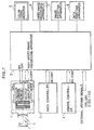
- Figure 1 shows the embodiment of the moving image judging apparatus of the invention.
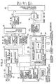
- Figure 2 shows an example of a high speed image processing apparatus according to the invention, for use in the judging apparatus.
- Figure 3 shows a front panel layout example of a main controller for an operator.
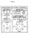
- Figure 4 shows a front panel layout example of a remote controller for a judge.
- Figure 5 shows an example of measurement setting display for a horse race.
- Figure 6 shows an example of measurement setting display for formal race starting scene in a motorboat race.
- Figure 7 shows an example of measurement setting display for a race finishing scene in a motorboat race.
- Figure 8 shows an example of a measurement setting picture for the starting scene of a race trial which is carried out as a practice before the formal race in a motorboat race.
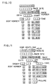
- Figure 9 shows a print out format example for horse race measurement.
- Figure 10 shows a print out format example of a formal race starting measurement setting, among several print out formats for measurement setting in a motorboat race.
- Figure 11 shows a print out format example of a finish measurement setting, among several print out formats for measurement setting in a motorboat race.
- Figure 12 shows a print out format example of a measurement setting for trial starting in a race trial mode.
- Figure 13 shows a print out format example of one race and whole races in a formal race mode.
- Figure 14 shows a print out format example of whole trials in a trial race mode.
- Figure 15 shows a configuration example for bus lines connecting a controller, a video memory and each of display memories.
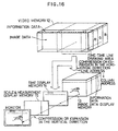
- Figure 16 is a figure to explain relationship between the video memory and each of display memories.
- Figure 17 shows an example of composed picture of recorded image data in the image data display memory, drawing information data in the time display memory and drawing information data in the scale & measurement display memory.
- Figure 18 shows an example of composed display for time measurement.
- Figure 19 shows an example of relationship between memory size of a video memory for image data and display size of a video monitor, and an example of display with a reduced size.
- Figure 20 shows an example of expansion or compression from a video display image, and an example of a reference position for expansion or compression.
- Figure 21 is a figure to explain calculation procedure in determining starting address for reading out.
- Figure 22 shows an example for composition of plurality of auxiliary lines with a video display image having zero second and one second time lines for a motorboat race.
- Figure 1 shows the embodiment of the moving image judging apparatus of the invention
- Figure 2 shows an example of a high speed image processing apparatus.
- Fig.1 shown are; a line sensing camera 1, a high speed image processing apparatus 2, a main controller 3, a remote controller 4, a color video monitor 5, a video image recording apparatus 6, an image printing apparatus 7 and a data printing apparatus 8.
- FIG.2 shown are; an A/D (analog to digital) conversion circuit 11, a video memory 12, an image data display memory 13, a time display memory 14, a scale & measurement display memory 15, a data composition circuit 16, a D/A(digital to analog) conversion circuit 17, an output signal switching circuit 18, a time data generating circuit 19, an information data memory 20, a power circuit 21, a controller 22, a synchronization signal generator 23, an ENC(encoder) 24, a memory 25, a memory controller 26, CPUs 27 and 28, a GP(graphic processor) 29, and an interface circuit for external connections 30.
- A/D analog to digital
- the moving image judging apparatus of the invention comprises; a line sensing camera 1 which generates an image of moving objects as time serial analog signals by scanning along one line orthogonal to the moving direction of the objects , a high speed image processing apparatus 2 which converts said analog electrical signals to digital image data signals, stores a part of said digital image data which correspond to a plurality of video display images, transfers the content of said video memory which corresponds to said video display images to an image data display memory and then converts the output of said image data display memory to analog output video signals 2, a main controller for an operator 3, a remote controller for a judge 4, a color video monitor 5, a video image recording apparatus 6, an image printing apparatus 7 and a data printing apparatus 8.
- the line sensing camera 1 is located on an eye line (M) which is in parallel with the finish line (L), the high speed image processing apparatus 2 and the main controller 3 are located at a suitable place in a building where an operator can carry out equipment operation, and the remote controller 4 and the color video monitor 5 are located at a place where a judge carries out judgment of races.
- Both analog and digital type apparatus can be used for the video image recording apparatus 6 and for the image printing apparatus 7.
- the color video monitor 5 is a CRT display terminal which displays analog output video signals from the high speed image processing apparatus 2.
- the video image recording apparatus 6 is equipment which can record and replay video data signals, such as a magnetooptic recording device(MO), a data streamer(DAT), a compact disc player(CD) or a video tape recorder(VTR).
- the line sensing camera 1 which comprises a set of zooming lenses, a color line sensor using charge coupled devices(CCD) as sensor elements, a sensor driver circuit and an output amplifier, is positioned so that it can take images along the vertical direction at the finish line.
- the color line sensor consists of a photo-electric converter which contains a one-dimensional array of photo-sensitive diodes each of which corresponds to one pixel and on each of which red(R), green(G) and blue(B) color filters are attached repeatedly in this order, and an output shift register.
- the color line sensor in the line sensing camera 1 has 1728 pixels, for example, for each color component.
- 16Kbytes in the line direction (horizontal direction) and 2Kbytes in the column direction (vertical direction) are assigned as the total storage area. From the 2Kbytes in the column direction,1728 bytes are assigned as the memory area for digital image data, and the remainning 320 bytes in the column direction are assigned as the memory area for information data (See fig.19 and fig.18).
- the invention is applicable for each type of video signal format, such as standard video signal format (NTSC), Hi-Vision video signal format and non-interlace Hi-Vision video signal format (PHD).
- the number of vertical scanning lines for a video display monitor are 485 for standard video, and 1035 for both Hi-Vision video and non-interlace Hi-Vision video.
- the number of pixels in the horizontal direction which actually corresponds to the resolution for the time axis is 1024 for every type of video signal formats.
- the A/D conversion circuit 11 in Fig.2 converts each R, G, and B component of analog video signal VSS to 8 bit image data PD corresponding to the gradation(or brightness, in other words) of each pixel.
- output data "00000000” is generated.
- output data "11111111” is generated by the conversion circuit.
- the video memory 12 is a DRAM( dynamic random access memory) which has a storage area for image data and a storage area for information data:
- the digital image data converted from R, G and B components of the analog video signal are stored in the storage area for image data, and the information data are stored in the storage area for the information data, respectively, at every scanning time(charge storage time) of the color line sensor.
- time and time lines can be drawn in a drawing area for time and time lines.
- Image data obtained by each scan are stored scan by scan in the vertical direction (or in the column addresses) of the storage area of the video memory 12.
- the image data are stored in the horizontal direction (or in the line addresses) time- sequentially for sixteen seconds at each 1/1000 second interval, for example.
- image data for sixteen pictures can be stored in this example.
- time data which correspond to operation modes such as the clockwise or counterclockwise course direction mode in horse races, the trial or formal race mode in motorboat races and the test mode, and other information on image data.
- the time data are provided by the time data generating circuit 19, and other information data are provided by a holding circuit for the race site data and the recording status data 20.
- the time data generating circuit 19 contains a timer, measures time by using a timer control signal TCS which is provided by the control circuit 22 and generates the time data (the elapsed time data).
- TCS timer control signal
- the holding circuit for the race site data and the recording status data 20 holds the information data from the control circuit 22, except the time data.
- the image data necessary for displaying and the information data are stored in the image data display memory 13 in preparation for displaying.
- the time display memory 14 stores data necessary for displaying time lines, time and the race site information on the video display image.
- the scale & measurement display memory 15 stores data necessary for displaying a scale line, auxiliary lines, measured time and a menu on the video display image.
- Each display memory 13, 14 or 15 consists of a video RAM which has a memory capacity of 2Kbytes in the line direction and 2Kbytes in the column direction.
- the image data necessary for displaying and the information data are transferred from the video memory 12 to the display memory 13 by using DMA (direct memory access) control, and the drawing information data for time and time lines are transferred also from the video memory 12 to the display memory 14 by using DMA control.
- the stored data in display memories 13 and 14, that is, the image data and the drawing information data for time and time lines, and the drawing information data stored in the display memory 15 are read out by a common video synchronization signal, to be transferred to the data composition circuit 16.
- the data composition circuit 16 combines the image data, the drawing information data for time and time lines, the drawing information data for the scale line and the like to compose complete drawing information data for one full screen size of display. Processing priorities are assigned to the scale & measurement display memory 15, the time display memory 14 and the image data display memory 13 in this order.
- the D/A conversion circuit 17 converts output data from the data composition circuit 16 as the horizontal image data HPD which are read out from each display memory to be composed as one picture scan on a video monitor screen, to analog video image signals VS.
- the controller 22 controls general operation of the whole apparatus of the invention, such as; selection of an operation mode according to a command from the main controller 3 which is operated by an operator or a command from the remote controller 4 which is operated by a judge; control of writing and reading of the video memory 12; generating conversion timing signals for the AID conversion circuit 11 and the D/A conversion circuit 17; generating Video synchronization signals; control of information data insertion; control of time count start or recording start triggered by an external signal; control of image data composition for the time display memory 14; control of image data composition for the time display memory 15, and the like.
- the controller contains two CPUs for such purposes.
- CPUa 27 mainly controls interfacing with external equipment, generating various operation commands according to commands from the main controller 3 for an operator and the remote controller 4 for a judge.
- the CPUb 28 executes each operation according to a command from the CPUa 27.
- CPUb 28 mainly controls a GP (graphic processor) 29, the video memory 12 and display memories 13, 14 and 15.
- the memory controller 26 controls writing and reading of image data for memories 12 to 15 using DMA control.
- the memory 25 consists of ROMs, RAMs, and EEPROMs for storing measurement data.
- the interface circuit (I/F) for external connection 30 consists of an external triggering signal I/F where such triggering signals are a time count start signal, a recording start signal, zero second signal for a motorboat race or one second signal for a motorboat race), a controller I/F (for both main and remote controllers), a camera control I/F and an external recording equipment I/F.
- the power circuit 21 consists of a power circuit for the high speed image processing apparatus, a power circuit for the line sensing camera and a power circuit for main and remote controllers.
- the synchronization signal generator 21 generates a composite synchronization signal SYNC, a horizontal synchronization signal HD and a vertical synchronization signal VD, which conform to any one of the standard video signal format, the Hi-Vision video signal format and the non-interlace Hi-Vision video signal format. Selection of a video signal format is made by video output selection function of the main controller 3.
- the encoder (ENC) 24 is an NTSC encoder which generates NTSC composite video signals.
- the output signal switching circuit 18 delivers standard NTSC video signal output, Hi-Vision video signal output or non-interlace Hi-Vision video signal output to a proper output port.
- Figure 3 shows a panel layout of the main controller for an operator
- Fig. 4 shows a panel layout for the remote controller for a judge
- Fig.5 to Fig.8 show image display examples for measurement settings
- Fig.9 to Fig.14 show print out examples for measurement settings.
- the main controller 3 for an operator and the remote controller 4 for a judge control various operation of the controller 22 in the high speed image processing apparatus 2.
- the main or remote controller comprises panels which have various operation buttons, LEDs and knobs. Functions of main panels of the main controller 3 will be explained hereinafter.
- the "recording mode panel” 42 comprises the "test” button which is used to select trial record mode for horse races or race trial mode for motorboat races, the " trial” button which is used only in motorboat race mode to select trial record mode and the "formal race” button which is used to select the race record mode for horse races and the formal race record mode for motorboat races. Selection of the horse race mode or the motorboat race mode is done using a mode selection switch 60 which is located at the rear side of the main controller(going out of sight in the fig.). The back up record button triggers recording compulsorily, regardless the menu setting for record start.
- the "control” panel 43 has the “main/remote” button which switches major control functions of the main control panel to the remote control panel and vice versa.
- the "video output” panel 44 comprises “P.HDTV” button which selects non-interlace Hi-Vision scanning signals as output signals, the “HDTV” button which selects Hi-Vision scanning signals as output signals and “NTSC” button which selects NTSC scanning signals as output signals.
- the "display” panel comprises sixteen "memory capacity” LEDs which display bar indication of written memory area of the image memory , sixteen “monitor display position” LEDs which indicates the starting address of reading the image memory, the "memory” LED which indicates that records are displayed in one of the record modes and the “external” LED which indicates that records are displayed based on an external recorder.
- the "menu” panel 46 has the “menu” button which demands menu display for equipment status settings and which demands measured data correction when in the measurement setting display mode.
- the "fix” panel 47 comprises the “fix” button which commands registration of race site and race date data (order number of the race event, the race date and the race number of the day), fixing of setting items, fixing of selected items when in the external equipment record mode, registration of measured data and start of printing out when in the measurement setting display mode, and finishing the race trial when in the race trial mode of motorboat races.
- the "setting status” panel 48 comprises the “horse race” LED, the "motorboat race” LED, the “clockwise” LED and the “counter clockwise” LED, which display the apparatus usage setting status whether it is a horse race, a motorboat race, in the clockwise course direction or in the counter clockwise course direction, respectively.
- the "time” panel 50 comprises the “reset” button which resets the display of the time indicator on the panel, the “start” button which triggers starting time count and the “external” LED which indicates whether starting time count is triggered by the "start” button or triggered by an external signal.
- the "record” panel 55 has the “record” button which triggers starting record of race trials which are held on a day before the formal horse races and of formal horse races, and which triggers starting record of trial and formal races in motorboat races, and the “race reset” button which interrupts recording after the record mode starts and returns the status to the initial stage of the record mode.
- the “race data setting” panel 56 comprises the "event number” button which selects and sets the order number data of the race event to display on the monitor screen, the "date” button which selects and sets the date data of the race event to display on the monitor screen, the “R” button which selects and sets the race number data to display on the monitor screen and the "auto” button which enables automatic one increment of the race number.
- the “event number” indicator, the “day” indicator and the “R” indicator displays the serial race event number, the date of the race event and the race number, respectively.
- the "auxiliary line” panel 57 comprises the "auxiliary line on/off” button which selects whether auxiliary lines for decision are displayed on the video monitor or not, the “single/plural” button which selects the number of auxiliary lines when the “auxiliary line on/off” button is set to “on”, the "auxiliary line number A” button and the “auxiliary line number B” button which set the number of auxiliary lines corresponding to the selection of the "selection A" (start) or the “selection B" (goal) buttons on the “picture selection panel” respectively, the "measurement on/off” button which selects whether measured data are displayed on the monitor screen or not and the “set” button which is used to input horse(boat) numbers and times of the race result for displaying.
- the "picture selection” panel 58 comprises the “selection A” button which selects camera 1 when in the horse race mode and selects the starting scene only for the formal race mode when in the motorboat race mode, the “selection B” button which selects camera 2 when in the horse race mode and selects the goal picture only for the formal race mode when in the motorboat race mode, "picture selection” sixteen-key buttons which are used for selection of display modes, and for setting of race site data or picture frame number, the "picture number” indicator which is used for indication of recorded frame numbers in each mode, indication of recording numbers in motorboat race trials, indication of starting picture number in external recording equipment and indication of replayed frame number, and the “selection” indicator which is used for indication of selected record frame number for each mode, indication of selected picture number for trial in a motorboat race and indication of the final picture number for external recording equipment.
- the "scroll” panel 59 has a joy stick which is used for moving an image to desired direction, for varying the scrolling speed and for extending the image size
- the horse race mode In recording a race trial using the horse race mode, images are recorded in the video memory for two picture frames so that the lens focusing around the targeted image can be adjusted correctly.
- time count is started by a time start signal and the image of finishing scene near the goal is stored in the video memory. After the time start signal received from the outside central clock triggers a timer to start counting and just before horses reach the goal, the operator of the apparatus starts recording by using the "record" button of the "record” panel 55. Time count is automatically stopped when pictures are stored to make the memory full, finishing recording of the formal race.
- Each formal race is recorded on the day of formal races. Recording is automatically started at a predetermined time selected from the recording start time menu (actually two seconds before the zero second), by using the external sixty seconds before zero signal from the central clock. The starting scene is recorded for about four seconds (four pictures). The timer is reset to zero by the zero second signal from the central clock, and the zero second line is written into the video memory at the same time. The one second line is also written into the video memory at the one second signal from the central clock. After finishing recording the starting scene, video image containing the zero second line and the one second line is displayed on a monitor screen for about 1.3 seconds. A judge can decide by the recorded video image on the screen whether there was a flying or a falling behind at the start. Time count is started by the zero second signal from the central clock, and the finishing scene near the goal is recorded in the rest of the video memory. When all of the video memory area become full, the time count is automatically stopped and the formal race recording is finished.
- the recorded video images are stored in external recording equipment such as an MO or a data streamer after recording by the apparatus was finished, using race data such as the event number, the event date or the race number as the name of the file.
- race data such as the event number, the event date or the race number as the name of the file.
- the recorded video images are read out from the external recording equipment by specifying the necessary file names, and then displayed on the monitor screen.
- Video image replay or other operations can be done just in the same status as in the record mode used (clockwise or counterclockwise course direction mode in horse races, the race trial mode or the formal race mode in motorboat races), by using the information data for video image data.
- the whole recorded area starting from the first picture frame is displayed sequentially at a constant scrolling speed which is set by a speed adjustment knob for automatic scrolling.
- the measurement mode a single line (as a scale line) and frames for indicating time along the scale line are displayed on the video monitor screen with time values themselves in the frames. Positions of the frames and the scale line are movable on the screen.
- the measurement display mode the number and the record time for each participant horse or boat are set and displayed.
- the measurement mode is activated to turn on the LED of the "on/off button", to turn off the LED of the "single/plural” button and to display the scale line and the frames for indicating time on the video monitor. Time values are displayed in the frames along the scale line. Time measurement is carried out by moving an auxiliary line to the nose position of the horse to be measured, using the "position" vernier dial.
- the measurement mode is inactivated to tern off video monitor display of the scale line and the frames for time values, and to turn off the LED of the "on/off” button.
- the measurement display mode is activated to turn on the LED of the "set” button, to display on the monitor screen the scale line and frames for time values, flashing on and off the indication of frames for horse numbers and for arrival orders.
- a single auxiliary line on the monitor screen can be moved to the nose position of the leading horse by adjusting the "position" vernier dial, and image scrolling can be done also to move the leading horse nose into the right half area of the video screen where is suitable for measurement.
- the frame indication of the time value flashes on and off for noticing by the operator.
- the time value for the auxiliary line position is displayed inside the frame, and the time value is registered at the push of "set” button.
- the similar procedures such as the horse image movement to the measurement area on the video screen, the auxiliary line movement to the horse nose position and entering and registration of the horse number, can be iterated for the next coming horse.
- Another push of the "set” button finishes and erases all display on the video screen, triggers memorization of all entered data, turns off the LED of the "set” button and changes the operation mode to the measurement mode.
- the "fix” button is pushed after entering whole necessary data, whole entered data are stored and printed out and the operation mode is changed to the measurement mode.
- the maximum data capacity which can be registered and stored in the apparatus is; data volume for twelve races with 20 participating horses per race in horse races, data volume for 12 start and finish scenes with 6 participating boats per each race in motorboat formal races, and data volume for 16 start scenes with 6 participating boats per each trial in motorboat race trials.
- Data for a specified race can be displayed on the video screen as shown in Fig.5 to Fig.8 or printed out as shown in Fig.9 to Fig.14, by entering the race number from the sixteen-key to specify the registered data for the race. Printing out data for the whole races or for a specified race is possible through selection from a menu.
- Video display examples for measurement settings are shown in Fig.5 for a horse race measurement setting, in Fig.6 for a measurement setting of a starting scene in a formal motorboat race, in Fig.7 for a measurement setting of a finishing scene in a formal motorboat race and in Fig.8 for a measurement setting of a starting scene in a motorboat race trial.
- Print out format examples for measurement settings are also shown in Fig.9 for a horse race measurement setting, in Fig.10 for a measurement setting of a starting scene in a formal motorboat race, in Fig.11 for a measurement setting of a finishing scene in a formal motorboat race, in Fig.12 for a measurement setting of a rehearsal scene of starting in a motorboat race trial, in Fig.13 for a measurement setting of one formal motorboat race and of whole formal motorboat races and in Fig.14 for a measurement setting of whole rehearsal scene in a motorboat race trial.
- While the operation mode is set to the clockwise course direction mode for horse races and if video data writing and reading directions along the horizontal addresses of the video memory are not changed from those in the counterclockwise course direction mode, images on the video monitor screen are displayed as mirror images of the original, moving into the reverse direction of the actual race. In order to avoid this inconvenience, writing and reading directions along the horizontal addresses of the video memory are changed automatically to the reverse direction in such cases.
- course direction information whether it is clockwise or counterclockwise is read from the information data among the video image data, so that writing and reading directions along the horizontal addresses of the video memory can be automatically changed according to the recording condition, enabling display of images moving in the same direction as actual races.
- Figure 15 shows a configuration example of bus lines connecting the controller, the video memory and display memories.
- Fig.16 is a figure to explain relationship between the video memory and each of display memories.
- the A/D conversion circuit 11, the video memory 12 and display memories 13 to 15 are connected through the high speed video image data bus (DMA data bus) D0.
- Video image data can be transferred rapidly from the A/D conversion circuit 11 to the video memory 12, through the high speed data bus D0 using DMA channel control.
- image data necessary for displaying, information data and drawing information data can be rapidly transferred from the video memory 12 to each of display memories 13 to 15.
- the video memory 12, each of display memory 13 to 15, CPUb 28 and GP 29 are connected to each other through the CPU controlled data bus D1.
- This bus line is used when CPUb 28 reads image data or information data in the video memory 12, when GP 29 draws time and time lines in the memory area for such data of the video memory 12, and when GP 29 draws drawing information data into each of display memories.
- the data bus D2 for reading out data from the image data display memory 13 and from the time display memory 14, and the data bus D2' for reading out data from the scale & measurement display memory 15 are connected to the data composition circuit 16. Image data and drawing information data are read out from each display memory 13 to 15 through these buses synchronously to the same video synchronizing signal, and then combined to one digital video data stream at the data composition circuit 16.
- the output of the data composition circuit is converted to analog video signal by the D/A conversion circuit 17 so as to be displayed on the video monitor screen.
- the CPUa-controlled address bus A0 is connected between the CPUa 27 and the memory controller 26.
- the address bus A4 which is used both as a CPUb-controlled address bus and as a drawing control address bus is connected between CPUb 28 and the memory controller 26.
- the DMA control address bus A1 is connected between the memory controller 26 and the video memory 12, and the CPUb-control address bus A1' is connected between the video memory 12, the controller CTLa 26-1 and the controller CTLb 26-2.
- the D/A display control address bus CTL is connected between the memory controller 26, the CTLa 26-1 and the CTLb 26-2.
- the display memory control bus A2 is connected between CTLa 26-1, display memories 13 and 14, and the display memory control bus A3 is connected between CTLb 26-2 and the display memory 15, respectively.
- the memory controller 26 is a memory manager which manages and controls such functions as control of connection interfaces to external equipment, DMA transfer control for data from the A/D conversion circuit 11, DMA transfer control for data transfer between memories, data writing in and reading from memories under CPU control and control for drawing information data, according to priorities.
- CPUa 27 controls mainly DMA transfer for the external equipment interface and A/D conversion, while CPUb 28 controls together with GP 29 reading/writing of memories and drawing information data.
- CPUa 27 sends a DMA control command to the memory controller 26, so that image data and information data can be stored in an RGB area of the video memory 12 through DMA channels.
- the memory controller 26 generates DMA addresses on the DMA control address bus A according to the command, causing image data and information data to be stored rapidly in the RGB area of the Video memory 12.
- CPUb 28 reads information data stored in the video RGB area of the video memory 12 and controls GP 29 to draw time values and time lines in the time and time line drawing area of the video memory as shown in Fig.16.
- CPUa 27 When video image display is required after recording is started, CPUa 27sends a DMA control signal to the memory controller 26 for transferring data stored in the video memory 12 to the image data display memory 13 and to the time display memory 14. Triggered by this DMA control signal, the memory controller 26 generates DMA addresses on the address bus A' in order that image data and information data are transferred to the image data display memory, and that drawing information data for time and time lines are transferred to the time display memory 14, respectively, under DMA transfer control as shown in Fig.16. Image data are then read out from the image data display memory 13 and from the time display memory 14 onto the data bus D2, combined with drawing information data at the data composition circuit 16 and converted to output analog video signals by the D/A conversion circuit 17.
- the memory controller 26 controls memories so that the image data writing and the information data writing into the video memory should be carried out simultaneously, and so that data transfers from the video memory 12 to display memories 13 and 14 should be carried out simultaneously.
- CPUb 28 When a command for scale line generation, for measurement or for measurement setting is received from one of the controllers, CPUb 28 generates drawing information data in cooperation with GP 29 according to the command from CPUa 27, transfers drawing information data to the scale & measurement display memory 15. The drawing information data are then read out from the scale & measurement display memory 15 onto the data bus D2', combined with image data from data bus D2 at the data composition circuit 16 and converted to output analog video signals by the D/A conversion circuit 17. An output image displayed on the video monitor screen is a still picture with its time axis being the horizontal axis of the monitor screen.
- measurement and display of the goal arrival time can be accomplished by generating an appropriate vertical scale line in the scale & measurement display memory and by measuring and displaying information corresponding to the position of this scale line.
- image data corresponding to several pictures on the monitor screen are stored sequentially in the video memory 12, and each display memory 13 to 15 has its own memory area of 2Kbytes in the line direction and 2Kbytes in the column direction, which are composed of VIDEO RAM devices.
- Vertical scanning line numbers of the video display on the monitor screen are 485 for the standard NTSC video format, and 1035 for both Hi-Vision and non-interlace Hi-Vision video formats.
- Pixel numbers for horizontal scanning lines corresponding to the time axis are 1024, being the same for all video formats.
- Image data and information data in the video memory 12 are transferred to the image data display memory 13, and drawing information data for time and time lines in the video memory 12 are transferred to the time display memory 14.
- Scrolling in the horizontal direction on the monitor screen can be carried out by shifting the reading out addresses in the horizontal direction of these display memories as shown in Fig.16.
- Scrolling in the vertical direction on the monitor screen can be carried out by shifting the reading out addresses in the vertical direction of display memories 13 and 14.
- image data and information data in the video memory 12 are initially compressed or expanded only in the horizontal direction (along line addresses).
- the horizontally compressed or expanded image data are transferred to the image data display memory 13 and also horizontally compressed or expanded drawing information data for time and time lines are transferred from the video memory 12 to the time display memory 14, and then these data are read out compressed or expanded only in the vertical direction (along column addresses) from display memories 13 and 14.
- Figure 17 shows an example for picture composition of recorded image data in the image data display memory, data in the time display memory and drawing information data in the scale & measurement display memory.
- Figure 18 shows an example for picture composition of time measurement.
- Image data and information data which are necessary for displaying video images are stored in the image display memory as shown in Fig.17(A).
- Black lines for separating each picture are inserted when intermittent recording which records discretely only necessary scenes is selected, and zero second line and one second line are also inserted in motorboat races.
- Time values 32 at each 1/10 second interval, time lines 33 at every 1/10 second or 1/100 second intervals, and event information display frame 31 are drawn in the time display memory as shown in Fig.17(B).
- Event data which consist of the race site name, the event number, the event date and the race number are drawn in the event information display frame 31. These event data based on information data are usually transferred from the time & time line display memory area in the video memory to the time display memory, but they can be also directly drawn in the time display memory based on the information data.
- a scale line 34, an auxiliary line 35 and a frame for time display 36 are drawn in the scale & measurement display memory, and the time value which corresponds to the position of the scale line 34 is drawn in the time display frame as shown in Fig.17(C).
- Data in these display memories are read out synchronously by the same video synchronization signal, composed and then converted to analog video signals to be displayed on the monitor screen as shown in Fig.17(D).
- the time display frame 36 is drawn first with the scale line 34 and the auxiliary line 35, and then the time value is drawn in the time display frame 36 based on the time data which are selectively read from information data in the image data display memory 12 according to the drawing position of the scale line 34.
- the time value in the time display frame 36 is automatically renewed to a new value which corresponds to the new scale line position.
- Figure 18 shows an example of video screen display at arrival order decision and time record acknowledgment in a horse race.
- the seventh arrival time is being acknowledged in this example.
- the time value of 1' 44" 17 which corresponds to the time data for the display position of the scale line is displayed in the time display frame and in a time record frame for arrival order record.
- measurement, display and record of arrival time for a race participant can be carried out by storing information data containing time data along with image data into the video memory time sequentially, and then reading time data among information data corresponding to the relationship between the image position and the scale line position. Consequently, both decision of arrival order and recording of time can be carried out by entering the back number of the horse according to the arrival order, moving the scale line to the nose position of the horse and then pushing the key for acknowledgment.
- time values or time lines are drawn in the time and time line drawing area prepared in the video memory and only the necessary area for displaying is read out with image data so as to be transferred to the image data display memory and to the time display memory
- the controller reads image data from the video memory and draws time or time lines in the time display memory, and it is also possible to select information to be drawn in the drawing area for time and time lines by using the information data.
- the high speed image processing apparatus described hereinbefore is such that image data and information data in the video memory are transferred to display memories, composed by the data composition circuit and then converted to analog output video signals by the D/A conversion circuit, a variation is possible such that image data and information data are recorded once in the video image recording apparatus and are read back from the recording apparatus to be stored in the video memory for replaying later.
- Figure 19(A) shows the relationship between the image data storage size of the video memory and the display size of the video monitor screen
- Fig.19(B) shows an example of compression and expansion in displaying.
- the color line sensor in the line sensing camera 1 has 1,728 pixels for each color component.
- 16Kbytes in the line direction and 2Kbytes in the column direction are assigned as the memory area.
- 1,728 bytes in the column direction are assigned as the memory area for image data and the rest of 320 bytes in the column direction are assigned as the memory area for information data.
- vertical scanning line numbers on the video monitor screen for the standard TV(NTSC), Hi-Vision TV(HD) or non-interlace Hi-Vision TV(PHD) video signal formats are 485, 1035 and 1035, respectively, when the video monitor conforms to such video signal formats.
- the pixel number in the horizontal scanning which corresponds to the time axis is 1024 for all of the video signal formats.
- Displaying images in the horizontal direction can be carried out not only by transferring image data sequentially from the video memory 12 to display memories 13 and 14 as horizontally continuous display mode, but also by transferring thinned out image data as horizontally thinned out display mode. Also there is a variation such that image data transfer from the video memory 12 are controlled in order that the number of displayed pixels in the still picture can be compressed or expanded by changing the read out pixel number per unit time in the horizontal direction as horizontal compression-expanding mode. As information data are transferred to the display memory 13 even if images are displayed as the horizontal compression-expanding mode, measurement of arrival time and display of the arrival time can be carried out by reading time data contained in the information data within the display memory 13, in response to the specified position of the scale line.
- the pixel number of the color sensor is selected as 1728 and the display area of the video monitor is set to 1035 pixels, it is possible to increase the pixel number of the color sensor in order to increase the image resolution. Thinning out ratio of image data displayed on the video monitor screen is not limited to 1/2 but also can be extended to 1/4 or to other values, according to the pixel number of the sensor and to the scope size. A black and white sensor can be also used instead of the color sensor.
- Figure 20 shows examples for compression and expansion of displayed images with reference position indication for the compression and expansion.
- Figure 21 shows the procedure to calculate the starting address of the display memories for reading out at compression or expansion of the image to be displayed.
- the moving object "c” which is running behind the moving objects "a” and “b” can be displayed within the screen area if the position of the scale line "m" is fixed at expansion, as shown in Fig.20(B).
- the start addresses for reading the display memories are fixed at expansion, the moving object "c” which is behind objects "a” and “b” falls out of the display area of the video screen, as shown in Fig.20(C).
- Expansion of the display area as shown in Fig.20(C) is common in conventional moving image judging apparatuses, whereas expansion of the display area as shown in Fig.20(B) is carried out in this invention.
- starting addresses for reading out the image data display memory 13 and the time display memory 14 are calculated using a prescribed position in the central area of the picture as a reference, and then image data and drawing information data are read out from the calculated starting addresses.
- pixel numbers are varied by changing the division ratio of a frequency divider in a PLL(Phase-Locked Loop) circuit so as to change the horizontal dot clock frequency, where the PLL is used to synchronize the horizontal dot clock to the edge of the horizontal video synchronizing signal.
- PLL Phase-Locked Loop
- the division ratio of the frequency divider in the PLL circuit is controlled by the controller 22 in order that the starting addresses for reading out the video display memory 13 and the time display memory 14 can be changed by calculating the values of starting addresses according to the change of the horizontal dot clock frequency in reference to the position of the scale line "m".
- Figure 21 shows an example of such calculating procedure.
- the ratio between the effective pixel number in the horizontal direction and the full displaying section is calculated from these data, and then the display starting address of SCALE DATA and the display starting address of MEMORY DATA can be changed to the new values, "s1' " and "s' ", respectively. It can be easily understood that the calculation method is not limited to the way described above, but other alternative ways can be possible without changing the spirit of the invention.
- the display position of the scale line is fixed and the display starting addresses is varied, but it is also possible to fix the display position at the center position of the picture and to change the display starting addresses.
- the above described display position correction method can be applied not only for the compression or expansion method using variable dot number of displayed images, but also for the compression or expansion method using thinning out or interpolating pixel number.
- the invention can also be applied in a case where images are thinned out in the vertical direction by a number of horizontal lines.
- images of moving objects passing the finish line can be fully taken from the inside to the outside of the race course and stored in the video memory.
- image data with continuous horizontal line numbers which can be displayed on the full video screen size are transferred from the video memory to the image data display memory, from which image data are read out so as to display the still picture of the inner side of the race course on the video monitor screen.
- Figure 22 shows an example of composition of a plurality of auxiliary lines on the video display image with the zero second line and the one second line for a motorboat race.
- the time display frame 36, the scale line 34 and a plurality of auxiliary lines 35 are drawn in the scale & measurement display memory 15 as shown in Fig.17(C) and are composed with the displayed image.
- Auxiliary lines are used for judging the goal arrival time difference in terms of horse lengths in a horse race, or for judging whether a flying was made or not by a race participant in a motorboat race.
- auxiliary lines 35 are displayed at the interval of 1/10 seconds between the zero second line 37 and the one second line 38 as shown in Fig.22. A judge reads time on the screen by sight using the auxiliary lines. As the auxiliary lines 35 are displayed on the screen together with the scale line 34, the zero second line 37 and the one second line 38, distinction between these lines may become difficult if they are displayed in the same color.
- the display color for the time value in the time display frame 36 is set red if the position of a moving object is before the zero second line 37 as like "a" shown in Fig.22, and set black if the object is between the zero second line 37 and the one second line 38.
- decision lines such as the scale line, auxiliary lines, the zero second line and the one second line are shown as examples to be displayed in different modes in the above explanation, the invention can be applied in a case where other decision lines are used.
- Image data and information data are sequentially stored according to time passing into storage areas for image data and information data which are assigned in video memory, only the necessary area for displaying is transferred to the display memory, information data which are to be composed with the displayed image are transferred to display memories, and then these data are read out and composed in synchronous to the video displaying signal as one output signal, as described hereinbefore.
- Another improvement by the invention is that the automatic measurement of time value at the position of the scale line becomes possible, because time data have been stored in the video memory as one part of the information data. Furthermore, high speed data processing becomes possible through simplified procedure, because each display memory is provided exclusively for image data, for time and timelines data and for the scale line and auxiliary lines, respectively, and composition of such data is carried out simultaneously at the data composition circuit. Hence automatic reading and recording of elapsed time using the scale line become possible, resulting in the reduction of judge's work loads in judging arrival order, acknowledgment of arrival time and recording. Reduction of errors in reading of elapsed time or judging arrival order, together with simple and sure acknowledgment or recording become thus possible.
- the invention it is possible by scrolling the displayed picture in the vertical direction or by displaying the whole vertical area using thinning out display mode, to recognize moving objects which have passed the finish line through the outer side of the race course even if they have not been displayed on the monitor screen because the vertical resolution of the monitor screen is raised in order to show the inner side of the race course, because the pixel number of the line sensor is set larger than the pixel number of the video monitor screen, image data for several number of pictures are stored in the video memory and image data are thin out or compressed/expanded when they are read out and displayed. Additionally, prompt acknowledgment of arrival order by looking the whole image of the race or prompt measurement of time difference by horse length in horse races become possible. Also, displaying scaled up in the horizontal direction in order to raise the horizontal resolution is possible, by increasing the displayed pixel number without thinning out image data.
- Another effect of the invention is that expansion or compression of displayed picture around a fixed interested position in the displayed picture is possible, because image data are read out from the video memory starting from the horizontal starting address which is calculated by using a prescribed center position in the displayed picture. Accordingly, a desired picture with compression or expansion around a prescribed position can be obtained through simple operation.
- Another effect of the invention is that misjudging or confusion in recognizing decision lines can be avoided when various decision lines are composed with the still image to be displayed on the video monitor screen so as to enable rapid and correct decision, because such lines are displayed in different display modes such as in different colors or using different kinds of lines. Additionally, confirmation of decision results such as whether there was a flying or not at the start of the race can be instantly carried out, because display modes for measured time values can be changed according to whether the position of the measured value is ahead or behind the reference line.
- the invention relates to a moving image judging apparatus wherein video signals of moving objects are taken by a line sensing camera 1 which scans in the direction orthogonal to the moving direction of said objects, said image signals are converted to image data and stored in a video memory 12 sequentially as a time sequence together with information data including time data for said image data, drawing information data for displaying images read out from necessary memory area are composed with said image data and then converted to analog video signals so as to be displayed as a video picture on a video monitor screen.
- the moving image judging apparatus is having a control means 22 which has a connection interface to external equipment, selects an operation mode according to a selection command from said controller, controls signal conversions from analog to digital and digital to analog, controls data composition of image data and drawing information data, controls reading and writing of a memory means for storage purpose and a memory means for display purpose, generates drawing information data and controls all of other necessary functions.
- control means 22 which has a connection interface to external equipment, selects an operation mode according to a selection command from said controller, controls signal conversions from analog to digital and digital to analog, controls data composition of image data and drawing information data, controls reading and writing of a memory means for storage purpose and a memory means for display purpose, generates drawing information data and controls all of other necessary functions.
- the apparatus is having display memories 13 and 14 wherein image data necessary for displaying are stored and afterwards read out in synchronous to a video displaying signal, compression or expansion of pixel numbers in the horizontal direction is carried out during the data transfer from the video memory to said display memories, and compression or expansion of pixel numbers in the vertical direction is carried out when display data are read out from said display memories in synchronous to the video displaying signal.
- the position of the scale line can be fixed around the center area of a monitor screen, even if the displayed image is compressed or expanded in the horizontal direction.
- compression or expansion of the displayed image in the horizontal direction is carried out by controlling the area of reading out from display memories 13, 14 and 15, in reference to the position prescribed by the scale line or the like on the displayed image.
Landscapes
- Engineering & Computer Science (AREA)
- Multimedia (AREA)
- Signal Processing (AREA)
- Closed-Circuit Television Systems (AREA)
- Controls And Circuits For Display Device (AREA)
- Image Processing (AREA)
Claims (11)
- Appareil d'évaluation d'image en mouvement pour afficher une image sur un écran d'affichage vidéo comprenant :dans lequel ledit appareil de traitement d'image comprend :(a) une caméra de détection linéaire (1) comprenant un détecteur linéaire ayant plus de pixels que le nombre de lignes de balayage vertical de l'écran d'affichage vidéo, et qui produit des signaux vidéo d'entrée d'images d'objets en mouvement en balayant lesdits objets en mouvement en utilisant des éléments de détection linéaire pour balayer dans une direction orthogonale à une direction de déplacement desdits objets en mouvement,(b) un appareil de traitement d'image vidéo (2) qui convertit lesdits signaux vidéo d'entrée venant de ladite caméra de détection linéaire en signaux numériques de données d'image, stocke lesdits signaux numériques de données d'image dans une mémoire vidéo (12) séquentiellement selon la séquence temporelle des balayages dudit détecteur linéaire, puis extrait lesdits signaux de données d'image stockés dans ladite mémoire qui sont nécessaires pour l'affichage et les convertit en signaux vidéo de sortie analogiques comme signaux de sortie,(c) un contrôleur (3, 4) pour ledit appareil de traitement d'image pour sélectionner un mode opératoire et contrôler l'appareil, et(d) un appareil de sortie extérieure qui affiche lesdits signaux vidéo de sortie analogiques en provenance dudit appareil de traitement d'image sur l'écran d'affichage vidéo (5),(p) lesdits moyens de mémoire vidéo ayant une première zone de mémoire pour stocker lesdits signaux numériques de données d'image destinés à être stockés séquentiellement selon la séquence temporelle et une seconde zone de mémoire pour stocker les données d'informations concernant lesdits signaux numériques de données d'image, lesdits moyens de mémoire vidéo (12) comprenant une mémoire vive dynamique (DRAM).(q) des moyens de mémoire d'affichage (13-15) dans un but d'affichage où lesdites données d'image nécessaires pour l'affichage et les données d'information graphique destinés à être composés composer avec lesdites données d'image sont écrites et ensuite extraites en synchronisation avec un signal d'affichage vidéo, comprenant une mémoire d'affichage des données d'image (13) où les données d'image et les données d'information en provenance de la mémoire vidéo sont stockées, une mémoire d'affichage de temps (14) où le temps, des lignes temporelles et des informations sur les images sont stockés comme lesdites données d'information graphique, et une mémoire d'affichage d'échelle et de mesure (15) où des lignes d'échelle pour la mesure du temps des images affichées sont stockées,(r) des moyens de composition et de sortie de données (16,17) qui composent lesdites données d'image et lesdites données d'information graphique et les convertissent en signaux vidéo de sortie analogiques, et(s) des moyens de contrôle (22) qui ont une interface de connexion avec l'équipement extérieur, sélectionnent un mode opératoire selon une commande de sélection venant dudit contrôleur, contrôlent lesdites conversions de signal d'analogique en numérique et de numérique en analogique, contrôlent ladite composition de données d'image et de données d'information graphique, contrôlent la lecture et l'écriture desdits moyens de mémoire vidéo (12) et desdits moyens de mémoire d'affichage (13-15), et génèrent lesdites données d'information graphique.
- Appareil d'évaluation d'image en mouvement selon la revendication 1, dans lequel :ledit appareil de traitement d'image a des moyens de génération de données temporelles (19) qui commencent à compter le temps lorsqu'ils sont déclenchés par un signal de départ et génèrent séquentiellement des données temporelles au moment de chaque balayage correspondant à un temps écoulé depuis le début du comptage de temps, et stockent les données temporelles générées par lesdits moyens de génération de données temporelles dans ladite seconde zone de mémoire comme données d'information.
- Appareil d'évaluation d'image en mouvement selon la revendication 1, dans lequel :lesdits moyens de mémoire vidéo (12) ont une troisième zone de mémoire pour stocker des données d'information graphique, lesdits moyens de contrôle génèrent des données d'information graphique à composer avec des données d'image basées sur lesdites données d'information stockées dans ladite troisième zone de mémoire, stockent les données d'information graphique dans ladite troisième zone de mémoire et écrivent ensuite les données d'information graphique dans les moyens de mémoire d'affichage en même temps que lesdites données d'image numériques.
- Appareil d'évaluation d'image en mouvement selon la revendication 1, dans lequel :ledit appareil de sortie extérieure comprend un appareil d'affichage comprenant l'écran d'affichage vidéo (5) pour afficher lesdits signaux vidéo de sortie analogiques, un appareil d'enregistrement d'images vidéo (6) pour enregistrer les données d'image et les données d'information, et un appareil d'impression de données (7,8) pour imprimer des images ou des données, ledit appareil de sortie extérieure extrait lesdites données d'image et données d'information dudit appareil de traitement d'image vidéo jusque dans ledit appareil d'enregistrement d'image vidéo, et ensuite renvoie les données d'image et les données d'information stockées dans ledit appareil d'enregistrement d'image vidéo (6) à l'appareil de traitement d'image vidéo pour les repasser.
- Appareil d'évaluation d'image en mouvement selon la revendication 3, dans lequel :lesdits signaux numériques de données d'image sont stockés dans lesdits moyens de mémoire vidéo (12) séquentiellement suivant une séquence temporelle en même temps que lesdites données d'information comprenant des données temporelles pour lesdits signaux numériques de données d'image, des données d'information graphique pour l'affichage d'images extraites d'une zone de mémoire sont composées avec lesdits signaux numériques de données d'image et ensuite convertis en signaux analogiques vidéo de façon à pouvoir être affichées comme une image vidéo sur l'écran d'affichage vidéo, une ligne d'échelle est composée et affichée sur ladite image vidéo, et ensuite un système automatique de mesure du temps est mis en oeuvre en lisant directement lesdites données temporelles qui correspondent à la position de la ligne d'échelle affichée.
- Appareil d'évaluation d'image en mouvement selon la revendication 1, ayant un mode d'extension/compression de nombre de pixels dans la direction horizontale, un mode d'expansion/compression de nombre de pixels dans la direction verticale et un mode d'expansion/compression de nombre de pixels dans les deux directions horizontale et verticale, dans lequel :ladite caméra de détection linéaire effectue ledit balayage à intervalles de temps constants prédéterminés pour produire lesdits signaux vidéo d'entrée, qui sont convertis en lesdits signaux numériques de données d'image et ensuite stockés dans lesdits moyens de mémoire vidéo (12) séquentiellement en même temps que lesdites données d'information comprenant des données temporelles pour lesdits signaux numériques de données d'image, le contenu d'une zone de ladite mémoire vidéo (12) nécessaire a l'affichage est extrait, composé avec les données d'information graphique qui sont générées selon lesdites données d'information, converti en lesdits signaux de sortie analogique d'image vidéo et ensuite affiché sur l'écran d'affichage vidéo (5), lesdits signaux numériques de données d'image dans ladite zone de mémoire nécessaires pour l'affichage sont écrits dans ladite mémoire d'affichage (13-15) et ensuite extraits en synchronisation avec un signal d'affichage vidéo, dans lequel l'extension ou la compression du nombre de pixels dans la direction horizontale est exécutée lors du transfert de données de ladite mémoire vidéo (12) vers ladite mémoire d'affichage (13-15), et l'extension ou la compression du nombre de pixels dans la direction verticale est exécutée lors de l'extraction à partir de ladite mémoire d'affichage en synchronisation avec le signal d'affichage vidéo.
- Appareil d'évaluation d'image en mouvement selon la revendication 1, dans lequel :lesdits moyens de contrôle calculent un nombre de pixel dans la direction horizontale à partir d'un signal d'horloge pour ledit signal d'affichage vidéo, et calculent le nombre de pixels entre une position de départ d'extraction et un point de référence pour lire à nouveau l'adresse de départ de ladite mémoire d'affichage de données d'image (13), l'adresse de départ de ladite mémoire d'affichage de temps (14) et l'adresse de départ de ladite mémoire d'affichage de mesure et d'échelle (15), selon un changement de fréquence d'horloge.
- Appareil d'évaluation d'image en mouvement selon la revendication 1, dans lequel :lesdits moyens de mémoire d'affichage (13) comprennent une mémoire vive (RAM) de vidéo qui a un espace mémoire plus grand que l'espace mémoire nécessaire à l'affichage d'une image sur l'écran d'affichage vidéo ;dans lequel des moyens sont fournis pour transférer les données d'image de sortie de tous les pixels produit par le dit détecteur linéaire séquentiellement desdits moyens de mémoire vidéo (12) à la mémoire vive de vidéo desdits moyens de mémoire d'affichage,et dans lequel des moyens sont fournis pour afficher l'une d'une première image prise du coté intérieur vers le coté extérieur d'un champ de course et d'une seconde image comprenant le coté extérieur du champ de course près de la ligne d'arrivée, avec l'image de l'intérieur du champ de course normalement affichée, mais quand l'objet en mouvement passe à l'extérieur de la zone affichée sur l'image initiale, la seconde image est affichée sur l'écran d'affichage vidéo au moyen de la compression desdites données d'image de sortie de tous les pixels produits par le détecteur linéaire dans la direction verticale.
- Appareil d'évaluation d'image en mouvement selon la revendication 1, dans lequel :ladite caméra de détection linéaire effectue ledit balayage à intervalles de temps constants prédéterminés,et dans lequel lors de l'extension ou de la compression de l'image vidéo affichée, lesdits moyens de contrôle (22) contrôlent les transferts des données d'image nécessaires pour l'affichage et des données d'information à partir desdits moyens de mémoire d'affichage (13-15), étendent ou compressent le nombre de pixels extraits desdits moyens de mémoire d'affichage en changeant une fréquence d'horloge horizontale pour affichage, déterminent la position de départ de lecture à partir desdits moyens de mémoire d'affichage selon une position prédéterminée dans l'image vidéo affichée en référence à la position de ladite ligne d'échelle, de façon telle que les images affichées sont compressées ou étendues dans la direction horizontale basée sur les positions lues.
- Appareil d'évaluation d'image en mouvement selon la revendication 1, dans lequel :ladite caméra de détection linéaire effectue ledit balayage à intervalles de temps constants prédéterminés,et dans lequel lors de l'expansion ou la compression de l'image vidéo affichée, lesdits moyens de contrôle (22) contrôlent les transferts des données d'image nécessaires pour l'affichage et des données d'information desdits moyens de mémoire d'affichage, étendent ou compressent le nombre de pixels extraits desdits moyens de mémoire d'affichage en synchronisation avec ledit signal d'affichage vidéo en changeant une fréquence d'horloge horizontale pour affichage, déterminent la position de départ de lecture à partir desdits moyens de mémoire d'affichage selon une position prédéterminée dans l'image vidéo affichée en référence à la position du centre d'une image affichée, de façon telle que les images affichées sont compressées ou étendues dans la position horizontale basée sur les positions lues.
- Appareil d'évaluation d'image en mouvement selon la revendication 1, dans lequel :lesdits moyens de contrôle (22) effectuent l'écriture des signaux numériques de données d'image comme une ligne d'échelle pour la mesure du temps ou une pluralité de lignes auxiliaires dans ladite mémoire d'affichage d'échelle et de mesure (15), et lesdits moyens de sortie composent ladite pluralité de lignes auxiliaires sur l'image affichée en utilisant des modes d'affichage différents pour des lignes différentes utilisant respectivement différentes couleurs ou différentes sortes de lignes.
Applications Claiming Priority (12)
| Application Number | Priority Date | Filing Date | Title |
|---|---|---|---|
| JP10891196A JP3224737B2 (ja) | 1996-04-30 | 1996-04-30 | 映像判定装置 |
| JP108909/96 | 1996-04-30 | ||
| JP10890996 | 1996-04-30 | ||
| JP10891296A JP3224738B2 (ja) | 1996-04-30 | 1996-04-30 | 映像判定装置 |
| JP10891296 | 1996-04-30 | ||
| JP108912/96 | 1996-04-30 | ||
| JP10891096 | 1996-04-30 | ||
| JP10891096A JP3224736B2 (ja) | 1996-04-30 | 1996-04-30 | 映像判定装置 |
| JP10890996A JP3224735B2 (ja) | 1996-04-30 | 1996-04-30 | 映像判定装置 |
| JP10891196 | 1996-04-30 | ||
| JP108911/96 | 1996-04-30 | ||
| JP108910/96 | 1996-04-30 |
Publications (3)
| Publication Number | Publication Date |
|---|---|
| EP0805595A2 EP0805595A2 (fr) | 1997-11-05 |
| EP0805595A3 EP0805595A3 (fr) | 1998-06-10 |
| EP0805595B1 true EP0805595B1 (fr) | 2002-03-20 |
Family
ID=27469681
Family Applications (1)
| Application Number | Title | Priority Date | Filing Date |
|---|---|---|---|
| EP96120185A Expired - Lifetime EP0805595B1 (fr) | 1996-04-30 | 1996-12-16 | Appareil de décision d'images animées |
Country Status (9)
| Country | Link |
|---|---|
| US (1) | US6104864A (fr) |
| EP (1) | EP0805595B1 (fr) |
| KR (1) | KR100229514B1 (fr) |
| AU (1) | AU722484B2 (fr) |
| CA (1) | CA2195158C (fr) |
| DE (1) | DE69619965T2 (fr) |
| MY (1) | MY119008A (fr) |
| SG (1) | SG66351A1 (fr) |
| TW (1) | TW340291B (fr) |
Cited By (1)
| Publication number | Priority date | Publication date | Assignee | Title |
|---|---|---|---|---|
| CN114005011A (zh) * | 2021-11-02 | 2022-02-01 | 中冶赛迪重庆信息技术有限公司 | 活畜在圈状态确定方法、系统、设备及介质 |
Families Citing this family (32)
| Publication number | Priority date | Publication date | Assignee | Title |
|---|---|---|---|---|
| JPH0934422A (ja) * | 1995-07-19 | 1997-02-07 | Sony Corp | 映像信号処理方法及び映像装置 |
| JPH10304190A (ja) * | 1997-04-23 | 1998-11-13 | Ricoh Co Ltd | 画像形成装置 |
| JPH1188742A (ja) * | 1997-09-09 | 1999-03-30 | Olympus Optical Co Ltd | 電子カメラ |
| US6545705B1 (en) * | 1998-04-10 | 2003-04-08 | Lynx System Developers, Inc. | Camera with object recognition/data output |
| JP4124892B2 (ja) * | 1998-07-24 | 2008-07-23 | キヤノン株式会社 | 通信装置及び通信方法及び記憶媒体 |
| US6985875B1 (en) * | 1999-11-05 | 2006-01-10 | Wolf Peter H | Process for providing event photographs for inspection, selection and distribution via a computer network |
| JP2002271797A (ja) * | 2001-03-08 | 2002-09-20 | Matsushita Electric Ind Co Ltd | 画像符号化装置、及び画像符号化方法,フレームレート変換装置 |
| US7554535B2 (en) * | 2001-10-05 | 2009-06-30 | Nec Corporation | Display apparatus, image display system, and terminal using the same |
| US8145448B2 (en) * | 2001-12-03 | 2012-03-27 | Fernando Vincenzini | System and process for charting and displaying the time and position of contestants in a race |
| US20050203651A1 (en) * | 2001-12-03 | 2005-09-15 | Fernando Vincenzini | System and process for charting the time and position of a contestant in a race |
| US7274803B1 (en) * | 2002-04-02 | 2007-09-25 | Videomining Corporation | Method and system for detecting conscious hand movement patterns and computer-generated visual feedback for facilitating human-computer interaction |
| KR20020092327A (ko) * | 2002-11-15 | 2002-12-11 | 주식회사 비솔 | 경주경기의 착순판정시스템 |
| KR20020092326A (ko) * | 2002-11-15 | 2002-12-11 | 주식회사 비솔 | 경정경주의 플라잉 판정시스템 |
| US6859547B2 (en) * | 2003-01-25 | 2005-02-22 | The Mostert Group | Methods and computer-readable medium for tracking motion |
| JP4545543B2 (ja) * | 2004-05-07 | 2010-09-15 | 任天堂株式会社 | ゲームシステムおよびゲームプログラム |
| EP1645944B1 (fr) * | 2004-10-05 | 2012-08-15 | Sony France S.A. | Interface pour une gestion de contenu |
| JP2010520565A (ja) * | 2007-03-02 | 2010-06-10 | オーガニック・モーション | 三次元の物体を追跡記録するシステム及び方法 |
| JP2009016934A (ja) * | 2007-06-29 | 2009-01-22 | Toshiba Corp | 映像再生装置 |
| US8135230B2 (en) * | 2007-07-30 | 2012-03-13 | Dolby Laboratories Licensing Corporation | Enhancing dynamic ranges of images |
| US20110269516A1 (en) * | 2009-11-03 | 2011-11-03 | Hoofs Up Left Right Or Evens Pty Ltd. | Game of Chance |
| USD697076S1 (en) * | 2011-03-24 | 2014-01-07 | Brother Industries, Ltd. | Handheld terminal with a graphical user interface |
| USD708203S1 (en) * | 2011-07-20 | 2014-07-01 | Zoocytium Holdings, Llc | Display screen with a graphical user interface |
| USD691173S1 (en) * | 2011-09-12 | 2013-10-08 | Microsoft Corporation | Display screen with animated graphical user interface |
| WO2013126931A2 (fr) * | 2012-02-22 | 2013-08-29 | Mobii Systems (Pty) Ltd | Système de chronométrage et procédé associé |
| JP5775840B2 (ja) * | 2012-03-22 | 2015-09-09 | 富士通フロンテック株式会社 | 通過順位入力システム、通過順位入力方法および通過順位確定支援装置 |
| WO2014013280A2 (fr) * | 2012-07-16 | 2014-01-23 | Polaritás-Gm Kft. | Module de base destiné à un appareil de démarrage de compétitions de bateaux |
| CN103442218B (zh) * | 2013-08-27 | 2016-12-28 | 宁波海视智能系统有限公司 | 一种多模式行为识别与描述的视频信号预处理方法 |
| US9897439B2 (en) * | 2014-05-26 | 2018-02-20 | Xiaomi Inc. | Method and terminal for measuring angle |
| CA3043490A1 (fr) | 2016-11-14 | 2018-05-17 | Gynesonics, Inc. | Procedes et systemes de planification et de surveillance en temps reel du deploiement d'une aiguille d'ablation dans un tissu |
| CN108837478B (zh) * | 2018-06-27 | 2020-03-27 | 重庆文理学院 | 一种基于机器视觉的用于跨栏比赛的犯规自动判别系统 |
| JP6627117B1 (ja) * | 2018-10-29 | 2020-01-08 | エスゼット ディージェイアイ テクノロジー カンパニー リミテッドSz Dji Technology Co.,Ltd | 画像処理装置、撮像装置、移動体、画像処理方法、及びプログラム |
| CN114374790A (zh) * | 2021-11-17 | 2022-04-19 | 北京航天试验技术研究所 | 一种航天发动机试验数据与图像的高精度同步方法 |
Family Cites Families (14)
| Publication number | Priority date | Publication date | Assignee | Title |
|---|---|---|---|---|
| US3890463A (en) * | 1972-03-15 | 1975-06-17 | Konan Camera Res Inst | System for use in the supervision of a motor-boat race or a similar timed event |
| FR2497369B1 (fr) * | 1980-12-31 | 1985-06-07 | Ssih Equipment Sa | Procede pour chronometrage de courses et dispositif pour la mise en oeuvre de ce procede |
| JPH0779470B2 (ja) | 1985-06-19 | 1995-08-23 | 株式会社プラスミック | 映像判定装置 |
| JPH0779471B2 (ja) | 1985-06-19 | 1995-08-23 | 株式会社プラスミック | 映像判定装置 |
| US4797751A (en) * | 1985-06-19 | 1989-01-10 | Yamaguchi Cinema Corporation | Electronic camera apparatus for recording and reproducing moving object images |
| JPH0779472B2 (ja) | 1985-06-19 | 1995-08-23 | 株式会社プラスミック | 映像判定装置 |
| JPS63316985A (ja) | 1987-06-19 | 1988-12-26 | Yamaguchi Shinema:Kk | 映像判定装置 |
| JPS63316987A (ja) | 1987-06-19 | 1988-12-26 | Yamaguchi Shinema:Kk | 映像判定装置 |
| JP2573492B2 (ja) | 1987-06-19 | 1997-01-22 | 株式会社 プラスミック | 映像判定装置 |
| JP2578346B2 (ja) | 1987-12-28 | 1997-02-05 | 株式会社プラスミック | スタート画像録画装置 |
| FR2648594B1 (fr) * | 1989-06-15 | 1993-03-05 | Omega Electronics Sa | Appareil pour le chronometrage de courses |
| JPH08506225A (ja) * | 1993-01-20 | 1996-07-02 | ジョン アリグザンドロビクス,ピーター | ラインモニタシステム |
| JPH06276526A (ja) * | 1993-03-22 | 1994-09-30 | Hitachi Denshi Ltd | カラー着順およびタイム判定装置 |
| JP3183318B2 (ja) * | 1994-05-20 | 2001-07-09 | 日立電子株式会社 | 着順およびタイム判定装置 |
-
1996
- 1996-12-16 EP EP96120185A patent/EP0805595B1/fr not_active Expired - Lifetime
- 1996-12-16 DE DE69619965T patent/DE69619965T2/de not_active Expired - Lifetime
- 1996-12-24 TW TW085116010A patent/TW340291B/zh not_active IP Right Cessation
-
1997
- 1997-01-13 AU AU10144/97A patent/AU722484B2/en not_active Ceased
- 1997-01-14 MY MYPI97000136A patent/MY119008A/en unknown
- 1997-01-15 CA CA002195158A patent/CA2195158C/fr not_active Expired - Fee Related
- 1997-02-17 SG SG1997000353A patent/SG66351A1/en unknown
- 1997-02-25 KR KR1019970005720A patent/KR100229514B1/ko not_active Expired - Fee Related
- 1997-04-09 US US08/840,302 patent/US6104864A/en not_active Expired - Fee Related
Cited By (1)
| Publication number | Priority date | Publication date | Assignee | Title |
|---|---|---|---|---|
| CN114005011A (zh) * | 2021-11-02 | 2022-02-01 | 中冶赛迪重庆信息技术有限公司 | 活畜在圈状态确定方法、系统、设备及介质 |
Also Published As
| Publication number | Publication date |
|---|---|
| AU722484B2 (en) | 2000-08-03 |
| US6104864A (en) | 2000-08-15 |
| CA2195158C (fr) | 2000-10-31 |
| CA2195158A1 (fr) | 1997-10-31 |
| EP0805595A2 (fr) | 1997-11-05 |
| DE69619965T2 (de) | 2002-08-08 |
| KR970072972A (ko) | 1997-11-07 |
| EP0805595A3 (fr) | 1998-06-10 |
| MY119008A (en) | 2005-03-31 |
| SG66351A1 (en) | 1999-07-20 |
| AU1014497A (en) | 1997-11-06 |
| DE69619965D1 (de) | 2002-04-25 |
| TW340291B (en) | 1998-09-11 |
| KR100229514B1 (ko) | 1999-11-15 |
Similar Documents
| Publication | Publication Date | Title |
|---|---|---|
| EP0805595B1 (fr) | Appareil de décision d'images animées | |
| EP0592136B1 (fr) | Génération et enregistrement d'images | |
| US5493331A (en) | Apparatus for judging the order of arrival of racers at a goal in a race and the time taken for the race, using color image pickup | |
| US7129980B1 (en) | Image capturing apparatus and automatic exposure control correcting method | |
| KR0149009B1 (ko) | 타이밍 경주용 장치 | |
| JPH08294073A (ja) | 合成画像投影装置及び画像調整方法 | |
| JPH04347979A (ja) | 画像合成撮影装置及び再生装置 | |
| JP3224735B2 (ja) | 映像判定装置 | |
| JPS5850882A (ja) | デイジタルコンバ−ゼンス装置 | |
| JP3224736B2 (ja) | 映像判定装置 | |
| JP3224738B2 (ja) | 映像判定装置 | |
| JP3224737B2 (ja) | 映像判定装置 | |
| JP2578346B2 (ja) | スタート画像録画装置 | |
| JPH09166609A (ja) | 速度測定画像処理装置 | |
| JPS61290881A (ja) | 映像判定装置 | |
| JPS61290880A (ja) | 映像判定装置 | |
| JPS61290882A (ja) | 映像判定装置 | |
| JPS63272294A (ja) | コンバ−ジエンス調整方法および装置 | |
| JPS61290879A (ja) | 映像判定装置 | |
| JP3690628B2 (ja) | パノラマ画像表示装置 | |
| JP3316220B2 (ja) | 画像入力装置 | |
| JP3222333B2 (ja) | 着順判定装置 | |
| JP2830941B2 (ja) | 映像判定装置 | |
| JPS63316985A (ja) | 映像判定装置 | |
| JPH03139374A (ja) | 電子式即時判定装置 |
Legal Events
| Date | Code | Title | Description |
|---|---|---|---|
| PUAI | Public reference made under article 153(3) epc to a published international application that has entered the european phase |
Free format text: ORIGINAL CODE: 0009012 |
|
| AK | Designated contracting states |
Kind code of ref document: A2 Designated state(s): DE FR GB |
|
| PUAL | Search report despatched |
Free format text: ORIGINAL CODE: 0009013 |
|
| AK | Designated contracting states |
Kind code of ref document: A3 Designated state(s): DE FR GB |
|
| 17P | Request for examination filed |
Effective date: 19980520 |
|
| 17Q | First examination report despatched |
Effective date: 20000814 |
|
| GRAG | Despatch of communication of intention to grant |
Free format text: ORIGINAL CODE: EPIDOS AGRA |
|
| GRAG | Despatch of communication of intention to grant |
Free format text: ORIGINAL CODE: EPIDOS AGRA |
|
| GRAH | Despatch of communication of intention to grant a patent |
Free format text: ORIGINAL CODE: EPIDOS IGRA |
|
| GRAH | Despatch of communication of intention to grant a patent |
Free format text: ORIGINAL CODE: EPIDOS IGRA |
|
| REG | Reference to a national code |
Ref country code: GB Ref legal event code: IF02 |
|
| GRAA | (expected) grant |
Free format text: ORIGINAL CODE: 0009210 |
|
| RIN1 | Information on inventor provided before grant (corrected) |
Inventor name: NARUKAWA, EIJIRO Inventor name: KONDO, NORIYUKI |
|
| AK | Designated contracting states |
Kind code of ref document: B1 Designated state(s): DE FR GB |
|
| REF | Corresponds to: |
Ref document number: 69619965 Country of ref document: DE Date of ref document: 20020425 |
|
| ET | Fr: translation filed | ||
| PLBE | No opposition filed within time limit |
Free format text: ORIGINAL CODE: 0009261 |
|
| STAA | Information on the status of an ep patent application or granted ep patent |
Free format text: STATUS: NO OPPOSITION FILED WITHIN TIME LIMIT |
|
| 26N | No opposition filed |
Effective date: 20021223 |
|
| PGFP | Annual fee paid to national office [announced via postgrant information from national office to epo] |
Ref country code: FR Payment date: 20110107 Year of fee payment: 15 |
|
| PGFP | Annual fee paid to national office [announced via postgrant information from national office to epo] |
Ref country code: GB Payment date: 20101221 Year of fee payment: 15 |
|
| PGFP | Annual fee paid to national office [announced via postgrant information from national office to epo] |
Ref country code: DE Payment date: 20101229 Year of fee payment: 15 |
|
| GBPC | Gb: european patent ceased through non-payment of renewal fee |
Effective date: 20111216 |
|
| REG | Reference to a national code |
Ref country code: FR Ref legal event code: ST Effective date: 20120831 |
|
| REG | Reference to a national code |
Ref country code: DE Ref legal event code: R119 Ref document number: 69619965 Country of ref document: DE Effective date: 20120703 |
|
| PG25 | Lapsed in a contracting state [announced via postgrant information from national office to epo] |
Ref country code: DE Free format text: LAPSE BECAUSE OF NON-PAYMENT OF DUE FEES Effective date: 20120703 Ref country code: GB Free format text: LAPSE BECAUSE OF NON-PAYMENT OF DUE FEES Effective date: 20111216 |
|
| PG25 | Lapsed in a contracting state [announced via postgrant information from national office to epo] |
Ref country code: FR Free format text: LAPSE BECAUSE OF NON-PAYMENT OF DUE FEES Effective date: 20120102 |