EP0805414A1 - Schrittmessvorrichtung, elektronisches gerät und schrittmessverfahren - Google Patents
Schrittmessvorrichtung, elektronisches gerät und schrittmessverfahren Download PDFInfo
- Publication number
- EP0805414A1 EP0805414A1 EP96935371A EP96935371A EP0805414A1 EP 0805414 A1 EP0805414 A1 EP 0805414A1 EP 96935371 A EP96935371 A EP 96935371A EP 96935371 A EP96935371 A EP 96935371A EP 0805414 A1 EP0805414 A1 EP 0805414A1
- Authority
- EP
- European Patent Office
- Prior art keywords
- frequency
- reference wave
- pitch
- harmonic
- determines
- Prior art date
- Legal status (The legal status is an assumption and is not a legal conclusion. Google has not performed a legal analysis and makes no representation as to the accuracy of the status listed.)
- Granted
Links
- 238000000034 method Methods 0.000 title claims description 39
- 230000033001 locomotion Effects 0.000 claims abstract description 105
- 238000005259 measurement Methods 0.000 claims description 70
- 238000004458 analytical method Methods 0.000 claims description 38
- 238000001514 detection method Methods 0.000 claims description 31
- 230000008569 process Effects 0.000 claims description 31
- 238000012790 confirmation Methods 0.000 claims description 28
- 238000004364 calculation method Methods 0.000 claims description 26
- 238000000691 measurement method Methods 0.000 claims description 18
- 238000001228 spectrum Methods 0.000 abstract description 35
- 239000011295 pitch Substances 0.000 description 166
- 230000006870 function Effects 0.000 description 40
- 238000010586 diagram Methods 0.000 description 23
- 230000008859 change Effects 0.000 description 18
- 239000004973 liquid crystal related substance Substances 0.000 description 13
- 238000012545 processing Methods 0.000 description 11
- 239000008280 blood Substances 0.000 description 10
- 210000004369 blood Anatomy 0.000 description 10
- 230000001133 acceleration Effects 0.000 description 8
- 210000000707 wrist Anatomy 0.000 description 8
- 238000003860 storage Methods 0.000 description 6
- 238000006243 chemical reaction Methods 0.000 description 5
- 238000000605 extraction Methods 0.000 description 5
- 238000011084 recovery Methods 0.000 description 4
- 101100328887 Caenorhabditis elegans col-34 gene Proteins 0.000 description 3
- 230000000694 effects Effects 0.000 description 3
- 230000000873 masking effect Effects 0.000 description 3
- 102000001554 Hemoglobins Human genes 0.000 description 2
- 108010054147 Hemoglobins Proteins 0.000 description 2
- 238000010521 absorption reaction Methods 0.000 description 2
- 238000001816 cooling Methods 0.000 description 2
- 238000009826 distribution Methods 0.000 description 2
- 238000005516 engineering process Methods 0.000 description 2
- 239000000284 extract Substances 0.000 description 2
- 230000005484 gravity Effects 0.000 description 2
- 230000009466 transformation Effects 0.000 description 2
- 102100036848 C-C motif chemokine 20 Human genes 0.000 description 1
- 101001139126 Homo sapiens Krueppel-like factor 6 Proteins 0.000 description 1
- 101000661807 Homo sapiens Suppressor of tumorigenicity 14 protein Proteins 0.000 description 1
- XUIMIQQOPSSXEZ-UHFFFAOYSA-N Silicon Chemical compound [Si] XUIMIQQOPSSXEZ-UHFFFAOYSA-N 0.000 description 1
- 101100524639 Toxoplasma gondii ROM3 gene Proteins 0.000 description 1
- 230000005540 biological transmission Effects 0.000 description 1
- 210000004204 blood vessel Anatomy 0.000 description 1
- 238000000295 emission spectrum Methods 0.000 description 1
- 239000011521 glass Substances 0.000 description 1
- 210000004247 hand Anatomy 0.000 description 1
- 230000001788 irregular Effects 0.000 description 1
- 238000004519 manufacturing process Methods 0.000 description 1
- 238000012544 monitoring process Methods 0.000 description 1
- 229910052757 nitrogen Inorganic materials 0.000 description 1
- IJGRMHOSHXDMSA-UHFFFAOYSA-N nitrogen Substances N#N IJGRMHOSHXDMSA-UHFFFAOYSA-N 0.000 description 1
- 230000010355 oscillation Effects 0.000 description 1
- 229910052698 phosphorus Inorganic materials 0.000 description 1
- 239000011574 phosphorus Substances 0.000 description 1
- 238000003825 pressing Methods 0.000 description 1
- 230000004044 response Effects 0.000 description 1
- 229910052710 silicon Inorganic materials 0.000 description 1
- 239000010703 silicon Substances 0.000 description 1
- 238000012360 testing method Methods 0.000 description 1
- 210000000623 ulna Anatomy 0.000 description 1
Images


Classifications
-
- G—PHYSICS
- G01—MEASURING; TESTING
- G01C—MEASURING DISTANCES, LEVELS OR BEARINGS; SURVEYING; NAVIGATION; GYROSCOPIC INSTRUMENTS; PHOTOGRAMMETRY OR VIDEOGRAMMETRY
- G01C22/00—Measuring distance traversed on the ground by vehicles, persons, animals or other moving solid bodies, e.g. using odometers, using pedometers
- G01C22/006—Pedometers
Definitions
- the invention relates to a pitch measurement device for measuring a pitch that indicates the frequency at which a body part such as the leg moves while walking or running, to an electronic instrument equipped with a pitch measurement function, and to a pitch measurement method; and more particularly to a technology for determining pitch from the body movement signals detected during running or walking.
- Pitch counters are known that use a means such as an acceleration sensor that can detect the movements of a body (body movements) to obtain body movement signals and that determine a pitch from these body movement signals.
- Conventional pitch counters for example, use a method that first amplifies body movement signals, converts them into pulses next, and then counts the pulses obtained.
- the pulse wave obtained using this method has irregular pulse intervals depending on the running state, resulting in large measurement errors even if the pulses are counted by setting a specific threshold value. Therefore, a method has been adopted that improves the detection precision by counting pulses in units of two using a mask signal that can set a specific non-sensitive time during pulse counting, as shown in Fig. 16 (a).
- the pitch indicating the frequency at which the right and left legs or hands move while running is normally between 150 to 200 times/minute, which can be converted into pulse cycles of between 0.3 to 0.4 seconds. Therefore, by using a mask signal with a masking time, or non-sensitive time, of 0.5 seconds, the pulse signals resulting from the conversion of body movement signals can be counted in units of two and pulses can be counted as pulses having pulse cycles of between 0.6 and 0.8 seconds. Therefore, pitches can be measured at high precision.
- the objective of the invention is to provide a pitch measurement device that does not require an external operation to switch between running and walking.
- Another objective of the invention is to provide a pitch measurement device that can easily and accurately measure pitch both during running and walking.
- Still another objective of the invention is to provide a user-friendly electronic instrument equipped with other multiple functions in addition to the pitch-measurement function, that can easily measure pitch. Therefore, it is also an objective of the invention to provide a pitch measurement method that can automatically determine whether a body movement signal was obtained during running or walking and that can calculate the pitch for either case. It is still another objective of the invention to provide a pitch measurement device and a pitch measurement method that can accurately determine whether a body movement signal was obtained during running or walking even when noise is present in the signal.
- harmonics such as the second harmonic which is two times the fundamental frequency and the third harmonic which is three times the fundamental frequency are obtained, and the intensity distribution of these harmonics have a distinct characteristics. That is, during running, a second harmonic is obtained that has an intensity (level) that is several times (3 to 10 times) the intensity of the fundamental harmonic having the frequency of the body movements. In contrast, during walking, the level of the second harmonic is equal to or smaller than the level of the fundamental harmonic; and a high-level third harmonic is obtained.
- the level of the second harmonic is lower, and is nearly equal to or lower than the level of the body's fundamental harmonic. It is thought that, because the swinging of the arms is also more moderate during walking, the level of the fundamental harmonic which has the same cycle as the body movement is higher than the second harmonic. Additionally, a high-level third harmonic is obtained which is a harmonic vibration of these other frequencies.
- the invention is designed to calculate pitch during both running and walking by analyzing the frequency of the result obtained from a body movement sensor and by determining whether a high-intensity (level) signal that appears at or above the specified frequency is the second or third harmonic.
- the pitch measurement device has a body movement sensor for detecting body movements, a frequency analysis means for analyzing the frequency of the detection result of said body movement sensor, and a pitch calculation means for calculating pitch during running or walking from the analysis result of said frequency analysis means; wherein said pitch calculation means sets a signal whose power is at least equal to the specified level in the region that is at or above the first frequency setting in the analysis result, as the reference wave to be referenced for determining pitch, and calculates pitch by determining whether or not this reference wave is the second or third harmonic corresponding to the body movement.
- the pitch displayed during running or walking is often twice the frequency of the body movement, i.e., the frequency of the second harmonic. Therefore, if the pitch calculation means determines the reference wave to be the second harmonic, it should preferably output the frequency of the reference wave as the pitch; and it should preferably output 2/3 of the reference wave frequency as the pitch if the reference wave is determined to be the third harmonic.
- the pitch measurement device can calculate pitch during both running and walking by simply determining whether the reference wave is the second or third harmonic, without using a mask signal, etc., and can output highly accurate pitches any time without requiring the user or the pitch measurement device to specify running or walking.
- the measurement device can measure pitch accurately both during running and walking, without the need for an external or internal operation to switch settings. Therefore, when measuring pitch using an electronic instrument into which other functions can be installed in addition to a pitch measurement function having a control device that can process signals from a body movement sensor and a display device that can display the output from this control device, the user can measure pitch easily and reliably without the need for selecting the running or walk setting.
- the pitch during walking is usually between 100 and 150
- the pitch during running is usually between 150 and 200. Therefore, it can be presumed that frequencies of 150 to 200 times/minute and 150 to 225 times/minute can be obtained for the second and third harmonics, respectively, and that any signals having frequencies lower than these are most likely noise. Therefore, this invention prevents pitch measurement errors caused by noise, by setting a value of around 100 times/minute, for example, which is sufficiently lower than the frequencies of the expected second and third harmonics, as the first frequency setting, and by evaluating signals having frequencies higher than this frequency setting.
- the first frequency setting is not limited to the aforementioned value and can be changed and adjusted by the person being measured or according to the measurement environment.
- a harmonic confirmation means that determines whether or not a high-level signal is present near at least a frequency that is 1/3 or 2/3 of the reference wave frequency inside the analysis result, and a signal determination means that determines the reference wave to be the second harmonic if no high-level signal is present near at least a frequency that is 1/3 or 2/3 of the reference wave frequency.
- a first wave confirmation means that determines whether or not a high-level signal is present near a frequency that is 1/3 of the reference wave frequency inside the analysis result can be adopted as the harmonic confirmation means, and the signal determination means can determine that the reference wave is the second harmonic if no high-level signal is present near a frequency that is 1/3 of the reference wave frequency.
- a second wave confirmation means that determines whether or not a high-level signal is present near a frequency that is 2/3 of the reference wave frequency inside the analysis result, and it can be determined that the reference wave is the second harmonic if no such signal is present.
- the harmonic confirmation means may determine whether or not a high-level signal is present near a frequency that is 1/3 or 2/3 of the reference wave frequency, and to determine that the reference wave is the second harmonic if no high-level signal is present near either a frequency that is 1/3 of the reference wave frequency or a frequency that is 2/3 of the reference wave frequency.
- the frequency of the third harmonic obtained during walking is more stable than the frequency of the second harmonic obtained during running, it is possible to adopt a signal determination means that determines that the reference wave is the second harmonic if the pitch calculation means determines that the frequency of the fundamental harmonic is equal to or less than the second frequency setting.
- the expected frequency of the third harmonic obtained as the reference wave during walking is between 150 and 225 times/minute, it is possible to adopt 150 times/minute as the second frequency setting and to determine that the reference wave is the second harmonic if it is equal to or less than the above frequency.
- the high-level signal near the 1/3 or 2/3 frequency is determined to be a noise as long as the frequency of the reference wave does not exceed the second frequency setting, and the reference wave can be determined to be the second harmonic.
- the method of calculating pitch by determining whether or not the reference wave is the second or third harmonic can also be used in a pitch measurement method that uses a personal computer, etc. for analyzing the detection result obtained from a body movement sensor. That is, the invention can provide a pitch measurement method having the steps described below.
- the pitch calculation process should preferably output the frequency of the reference wave as the pitch if the reference wave is determined to be the second harmonic, and should preferably output 2/3 of the reference wave frequency as the pitch if the reference wave is determined to be said third harmonic.
- processes equipped with the aforementioned functions such as a harmonic confirmation process that determines whether or not a high-level signal is present near at least a frequency that is 1/3 or 2/3 of said reference wave frequency inside the analysis result, and a signal determination process that determines that the reference wave is said second harmonic if no high-level signal is present near a frequency that is 1/3 or 2/3 of the reference wave frequency.
- Such a pitch measurement method according to the invention can be provided as a software program equipped with the aforementioned processes, and can be provided as a program stored in a medium such as a magnetic recording medium or ROM that can be read by a computer or microprocessor.
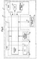
- Fig. 1 is a diagram showing the external appearance of a portable electronic instrument in which the pitch measurement function according to the invention has been installed, and how this instrument is used.
- Fig. 2 is a block diagram showing a schematic configuration of the portable electronic instrument shown in Fig. 1.
- Fig. 3 is a block diagram showing a schematic configuration of the pitch measurement device installed in the electronic instrument shown in Fig. 1.
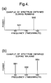
- Fig. 4 is a diagram showing examples of the spectrum obtained from analyzing the frequency of body movement signals; Fig. 4 (a) shows an example of a spectrum obtained during running; Fig. 4 (b) shows an example of a spectrum obtained during walking.
- Fig. 5 is a flow diagram showing the processing in the pitch measurement device shown in Fig. 3.
- Fig. 6 shows the top view of the device main body of the portable electronic instrument shown in Fig. 1.
- Fig. 7 is a diagram of the device main body of the portable electronic instrument shown in Fig. 1, viewed from the 3 o'clock direction of the watch.
- Fig. 8 is a cross-sectional diagram of the pulse-detection sensor unit used in the portable electronic instrument shown in Fig. 1.
- Fig. 9 is a block diagram schematically showing the configuration of the pulse wave detection device installed in the portable electronic instrument shown in Fig. 1.
- Fig. 10 is a diagram showing the various modes of the portable electronic instrument shown in Fig. 1.
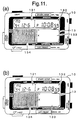
- Fig. 11 (a) is a diagram showing the indicator display when the clock mode is selected;
- Fig. 11 (b) is a diagram showing the state in which this indicator display has been turned off.
- Fig. 12 is a diagram for explaining the functions in the running mode of the portable electronic instrument shown in Fig. 1 when the instrument is a pitch and pulse counter.
- Fig. 13 (a) is a diagram for explaining the content of the display when the pitch and pulse counter is switched to the running mode;
- Fig. 13 (b) is a diagram for explaining the display state before pulse count measurement begins.
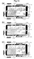
- Fig. 14 (a) is a diagram for explaining the content of the display after pulse count measurement begins in the running mode but before the pulse count reaches the specified range, when the instrument is a pitch and pulse counter;
- Fig. 14 (b) is a diagram for explaining the content of the display after the pulse count reaches the specified range; and
- Fig. 14 (c) is a diagram for explaining the display state for showing the changes in the pitch over time.
- Fig. 15 (a) is a diagram for explaining the content of the display after an instruction for stopping pulse counting is received by the portable electronic instrument shown in Fig. 1 and the pulse count is within the specified range;
- Fig. 15 (b) is a diagram for explaining the content of the display when the pulse count goes outside the specified range.
- Fig. 16 (a) is a waveform diagram in a conventional pitch counter after a body movement signal obtained during running is converted to pulses
- Fig. 16 (b) is a waveform diagram in a conventional pitch counter after a body movement signal obtained during walking is converted to pulses.
- Fig. 1 shows a wristwatch type portable electronic instrument equipped with the pitch measurement function according to the invention.
- This portable electronic instrument 1 is provided with a clock function that can be used as a wristwatch, a pulse count measurement function that can measure and display a pulse wave, and with a pitch measurement function that can measure a pitch that indicates the frequency of movements of a body part, such as an arm or leg, during running or walking.
- portable electronic instrument 1 in this embodiment is equipped with device main body 10 possessing a wristwatch structure, and this main body contains body movement sensor 90, such as an acceleration sensor, for detecting the movements in the user's body (body movements), and control area 5 for implementing the aforementioned various functions, etc.
- body movement sensor 90 such as an acceleration sensor
- Liquid crystal display device 13 which displays various data such as time, pulse, and pitch as well as performing a user-interface function, is installed on the surface of main body 10; and furthermore, multiple operation switches 111, 112, 113, 114, 115, 116, and 117 for controlling the various functions are installed on the top and side surfaces of main body 10. Additionally, pulse wave detection sensor unit 30 is connected to main body 10 via cable 20, so that pulse waves from the finger can be detected.
- Wristband 12 which is wrapped around the wrist from the 12 o'clock direction of the wristwatch (hereafter, all directions relative to main body 10 will be indicated in terms of clock directions) and fastened in the 6 o'clock direction, is installed in said main body 10, enabling device main body 10 to be detachably mounted on the user's wrist.
- Fig. 2 shows a schematic configuration of electronic instrument 1 of this embodiment in a block diagram.
- Electronic instrument 1 of this embodiment is configured around control area 5 which comprises an element such as a microprocessor, and is provided with ROM3 which stores the programs and data necessary for processing in said control area 5, RAM4 to be used as a temporary storage area for processing and for accumulating measurement data, etc., and control area 2 for controlling control area 5.
- Control area 2 is provided with various switches 111 through 117 installed on the top surface or perimeter of main body 10 as explained above.
- electronic instrument 1 of this embodiment is equipped with liquid crystal panel 13 for user interface as explained above, and said liquid crystal display device 13 displays information such as time, measured data, and processing mode.
- Electronic instrument 1 of this embodiment is additionally provided with real-time clock (RTC) unit 6 which has an oscillation function for timing, a function for measuring time of day and date, etc.; and clock processing area 54 which performs various clock operations (to be explained below in conjunction with the operation of the electronic instrument) is configured utilizing the functions of this RTC unit 6.
- RTC real-time clock
- electronic instrument 1 of this embodiment is equipped with pitch measurement area 56 which can measure a pitch by using control area 5 to process the signal from body movement sensor 90 housed inside main body 10, and with pulse measuring area 55 which can measure pulses by using control area 5 to process the signal from pulse wave sensor 30 which is connected with main body 10 via cable 20.
- Fig. 3 shows more detailed configuration of pitch measurement area 56 of this embodiment.
- body movements are detected by body movement sensor 90 and the resulting signals are input into body movement signal conversion area 561 of control area 5.
- Body movement signal conversion area 561 amplifies the signal obtained by body movement sensor 90 and at the same time converts the signal into easy-to-process digital data, and then outputs and temporarily stores this data in body movement signal storage area 562 of RAM4.
- a processing device such as a personal computer, and use the data for analyzing pitch.
- the data accumulated in body movement signal storage area 562 is fetched by frequency analysis area 569 of control area 5 at the specified intervals and its frequency is analyzed.
- Frequency analysis area 569 is provided with body movement signal calculation area 563 which reads the signals stored in body movement signal storage area 562 and applies frequency analysis and fast Fourier transformation (FFT processing) to the signals, and with body movement component extraction area 564 which can extract a frequency and a signal intensity (level) from the frequency analysis result as body movement components.
- the body movement components extracted by body movement component extraction area 564 are supplied to pitch calculation area 560 provided in control area 5, the pitch during running or walking is calculated by this pitch calculation area 560, and the result can be displayed on liquid crystal display device 13.
- Pitch calculation area 560 of this embodiment is provided with signal identification area 565 which identifies a signal whose intensity is at least equal to the specified level in the area that is at least equal to the specified frequency (first frequency setting) as the reference wave to be referenced for determining a pitch, first wave confirmation area 566 which determines whether or not a high-level signal is present near a frequency that is 1/3 of the identified reference wave frequency, second wave confirmation area 567 which determines whether or not a high-level signal is present near a frequency that is 2/3 of the reference wave frequency, and with signal determination area 568 which determines that the identified reference wave is the second harmonic for the fundamental harmonic equipped with the body movement's basic frequency if first wave confirmation area 566 determines that no high-level signal is present near a frequency that is 1/3 of the reference wave frequency and if second wave confirmation area 567 determines that no high-level signal is present near a frequency that is 2/3 of the reference wave frequency.
- Signal determination area 568 determines that the identified reference wave is the third harmonic for the fundamental harmonic if the confirmation results of first wave confirmation area 566 and second wave confirmation area 567 show that a high-level signal is present near a frequency that is 1/3 or 2/3 of the reference wave frequency. However, in this operation, signal determination area 568 is designed to determine that the reference wave is the third harmonic only if the reference wave is at least equal to the specified frequency (second frequency setting) and to determine that the reference wave is the second harmonic if the reference wave is equal to or less than the second frequency setting.
- Fig. 4 shows examples of the signal (spectrum) obtained by body movement
- Fig. 4 (a) shows an example of a spectrum obtained during running
- Fig. 4 (b) shows an example of a spectrum obtained during walking. Since a distinct difference exists between the spectrums obtained during running and walking as shown in these figures, pitch measurement area 56 of this embodiment is designed to automatically sense this difference in spectrum and to automatically measure accurate pitch during running or walking.
- the pitch (the frequency of the second harmonic is normally used) during running is between 150 and 200 times/minute and the pitch during walking is between 100 and 150 times/minute
- the second harmonic during running and the third harmonic during walking appear in approximately the same frequency band. Therefore, by identifying a high-level signal that is at least equal to the specified frequency (first frequency setting) and by determining whether this signal is the second or third harmonic, whether a spectrum was obtained from body movements caused by running or walking can be automatically determined.
- a value that is 2/3 the frequency as the pitch if the signal is determined to be the third harmonic a highly accurate pitch can be displayed or output regardless of whether the user is running or walking.
- this signal can be determined to be the third harmonic
- the pitch during walking can be calculated from the value resulting from multiplying the frequency of this signal by 2/3.
- the second harmonic for the fundamental harmonic will appear as a high-level signal in the frequency region at or above 100 times/minute during running. Therefore, if this signal can be determined to be the second harmonic, the pitch during running can be calculated from the frequency of this signal.
- step ST1 signal identification area 565 is used to identify the highest-level signal (line spectrum) from among the spectrums extracted after frequency analysis. This signal is identified as the reference wave to be referenced during pitch determination.
- step ST2 the frequency (Fb) of this reference wave is compared to 100 times/minute which is the first frequency setting. If the frequency of the reference wave is less than 100 times/minute, the highest-level signal is retrieved from among the signals that exclude the earlier signal, in step ST3. If no applicable signal is found in step ST3, the processing explained below is bypassed and the operation shifts to signal determination area 568, and the pitch calculated in the previous round is processed as the current pitch in step ST10, and then the processing is completed.
- step ST3 if the next level signal is detected in step ST3, the operation shifts to step 4[??] and the highest-level signal among the signals that exclude the earlier signal is identified as the reference wave. The operation then returns to step ST2 and the frequency of this reference wave is compared to the first frequency setting.
- step ST5 uses first wave confirmation area 566 to determine whether a signal possessing an intensity (amplitude or level) that is at least 1/2 of the intensity (amplitude or level) of the reference wave is present near a frequency that is 1/3 of frequency Fb of the identified reference wave. If the reference wave is the third harmonic, a high-level signal indicating the fundamental harmonic of the body movement should appear near a frequency that is 1/3 of frequency Fb of the reference wave; and by detecting this signal, it is possible to determine whether this signal is the second or third harmonic.
- determining whether or not a high-level signal is present near a frequency that is 1/3 of the reference wave frequency it is preferable to determine that a high-level signal is present near a frequency that is 1/3 of the reference wave frequency if that signal is within the range of +/- 1 resolution of the frequency resolution in which the aforementioned line spectrums are obtained; and if a higher resolution is available, it is preferable to select a frequency range that corresponds to that resolution as the determination target, although the actual situation will depend on the capability of frequency analysis area 569 which performs frequency analysis.
- step ST6 If it is determined in step ST5 that no signal having at least 1/2 the level of the reference wave is present near a frequency that is 1/3 of frequency Fb of the reference wave, the operation shifts to step ST6.
- second wave confirmation area 567 is used to determine whether or not a signal having at least 1/2 the level of the reference wave is present near a frequency that is 2/3 of the reference wave frequency. If the reference wave is the third harmonic, a high-level signal indicating the second harmonic should appear near a frequency that is 2/3 of frequency Fb of the reference wave; and by detecting this signal, it is possible to determine whether this signal is the second or third harmonic. It is preferable in this step, as in the earlier step, to select a frequency range that corresponds to the resolution used for frequency analysis as the determination target.
- steps ST5 and ST6 i.e., first wave confirmation area 566 or second wave confirmation area 567
- steps ST5 and ST6 i.e., first wave confirmation area 566 and second wave confirmation area 567
- steps ST5 and ST6 can be used to determine whether a signal is the second or third harmonic.
- Using such a configuration makes it possible to accurately calculate the pitch even for a user whose body movement pattern is slightly different from a normal one, e.g., the fundamental or second harmonic level is extremely low in the state in which the third harmonic can be obtained (during walking).
- a signal is determined to be high if its level is at least 1/2 the level of the reference wave in this embodiment, this value is just an example and any level is of course acceptable as long as it can be differentiated from the noise contained in the signal obtained after amplifying and converting the signal from a body movement sensor and after analyzing this signal's frequency.
- the reference wave can be determined to be a signal equivalent to the second harmonic. Therefore, the operation shifts to step ST8, and signal determination area 568 calculates frequency Fb of the reference wave itself as the pitch.
- signal determination area 568 calculates frequency Fb of the reference wave itself as the pitch.
- the operation shifts to step ST7 and frequency Fb of the reference wave is compared to 150 times/minute which is the second frequency setting.
- This second frequency setting of 150 times/minute is a value that is 1.5 times the first frequency setting value of 100 times/minute.
- the pitch during walking is between 100 and 150 times/minute, and a reference wave of between 150 and 225 times/minute is expected to be obtained as the third harmonic.
- the pitch during running is between 150 and 200 times/minute, and a reference wave having nearly identical frequency of between 150 and 200 times/minute is expected to be obtained as the second harmonic.
- the identified reference wave is determined to be the third harmonic only if frequency Fb of the reference wave is determined to be 150 times/minute or higher in step ST7.
- frequency Fb of the reference wave is lower than 150 times/minute, the high-level signal detected in step ST5 or ST6 is simply a noise and the reference wave is determined to be the second harmonic.
- This second frequency setting of 150 times/minute is of course just an example value and can be changed/adjusted by the user or based on the measurement condition.
- the pitch measurement device can automatically calculate extremely accurate pitches by adapting to the changes in conditions during running or walking.
- step ST7 If the reference wave is determined to be the second harmonic in step ST7, the operation shifts to step ST8 and frequency Fb of the reference wave is output as the pitch as explained above. On the other hand, if the reference wave is determined to be the third harmonic, the operation shifts to step ST9 and frequency Fb of the reference wave is multiplied by 2/3 and is output as the pitch. Of course, to adopt the fundamental harmonic of the body movement as the pitch, it is necessary to calculate 1/3 frequency Fb of the reference wave.
- pitch measurement area 56 equipped with the aforementioned functions can be implemented as one of the functions of a multi-function electronic instrument 1 as in this embodiment, or can be provided as a pitch counter equipped with a single pitch measurement function.
- the process of determining a pitch explained based on Fig. 5 can also be implemented as a software program when using a personal computer, etc. to analyze the data obtained from a body movement sensor.
- a software program that utilizes the pitch measurement method according to the invention does not require the user to specify running or walking and yet can automatically determine whether the user is running or walking, can calculate pitch according to the condition at an extremely high accuracy, and can be applied to various analysis programs.
- Such a software program can be provided as a program stored in a magnetic recording medium such as a floppy disk and hard disk, or in a medium such as a CD and ROM that can be read by a computer, microprocessor, etc.
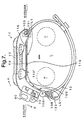
- pulse wave detection sensor unit 30 is connected via cable 20 to main body 10 of portable electronic instrument 1 in this embodiment, having the wristwatch structure.
- Connector piece 80 is provided on the tip side of cable 20, and said connector piece 80 can be detachably installed in connector area 70 provided on the 6 o'clock side of device main body 10.
- Pulse wave detection sensor unit 30 is attached to the area between the base and the first joint of the index finger and is shielded from light by sensor-fastening strap 40. Attaching pulse wave detection sensor unit 30 to the base of a finger in this way keeps cable 20 short and prevents it from getting in the way during running.
- the temperature at the finger tip falls substantially, while the temperature at the base of the finger falls relatively little. Therefore, attaching pulse wave detection sensor unit 30 at the base of the finger enables pulse count, etc. to be accurately measured even while running outside on a cold day.
- Fig. 6 shows main body 10 of the portable electronic instrument of this embodiment, with the wristband and cable removed;
- Fig. 7 shows a view of portable electronic instrument, obtained from the 3 o'clock direction of the main body.
- device main body 10 of this embodiment is provided with plastic watch case 11 (body case), and the top side of this watch case 11 is provided with liquid crystal display device 13 (display device) with an EL backlight for displaying running time, pitch during walking, and pulse wave information such as pulse count, in addition to current time and date.
- Liquid crystal display device 13 is provided with first segment display area 131 positioned on the upper left side of the display surface, second segment display area 132 positioned on the upper right side of the display surface, third segment display area 133 positioned on the lower right side of the display surface, and dot display area 134 positioned on the lower left side of the display. Dot display area 134 can graphically display various types of information.
- body movement sensor 90 for determining a pitch is housed inside watch case 11, and an acceleration sensor, etc. can be used as this body movement sensor 90.
- control area 5 which performs various types of control and data processing in order to determine a pitch based on the detection result (body movement signal) obtained by body movement sensor 90 and to display the result on liquid crystal display device 13, as well as in order to determine the change in pulse count based on the detection result (pulse wave signal) obtained by pulse wave detection sensor unit 30 and to display the result on liquid crystal display device 13, is provided inside watch case 11.
- Control area 5 is also provided with a timing circuit and thus can display normal time, lap time, split time, etc. on liquid crystal display device 13.
- Button switches 111 through 115 which are used for external operations such as time adjustment and display mode switching, are provided on the perimeter of watch case 11. Additionally, larger button switches 116 and 117 are provided on the surface of the watch case. Furthermore, button-shaped small battery 59 which acts as the power supply for portable electronic instrument 1 is housed inside watch case 11, and electrical power can also be supplied from battery 59 to pulse wave detection sensor unit 30 via cable 20. This cable 20 is also used for inputting the detection result of pulse wave detection sensor unit 30 into control area 5 of watch case 11.
- portable electronic instrument 1 of this embodiment is a multi-function device
- the size of device main body 10 must be increased as more functions are added.
- watch case 11 is extended in the 3 and 9 o'clock directions
- wristband 12 is connected eccentrically toward the 3 o'clock side, leaving large extended area 101 in the 9 o'clock direction of the wristwatch, viewed from wristband 12.
- no such extended area is provided in the 3 o'clock direction. Consequently, this structure, despite the use of long watch case 11, allows free wrist movement and eliminates the possibility of the back of the hand striking watch case 11 during a fall.
- Flat piezoelectric element 58 for a buzzer is positioned in the 9 o'clock direction, viewed from battery 59, inside watch case 11.
- Battery 59 which is heavier than piezoelectric element 58 is positioned eccentrically in the 3 o'clock direction so that the center of gravity of device main body 10 is shifted in the 3 o'clock direction. Because wristband 12 is connected to a spot near this center of gravity, device main body 10 can be securely attached to the wrist.
- the positioning of battery 59 and piezoelectric element 58 in the planar direction allows device main body 10 to be thin, and battery cover 118 installed on the back side as shown in Fig. 7 allows the user to easily replace battery 59.
- connecting area 105 for holding stopping pin 121 installed on the end of wristband 12 is formed in the 12 o'clock direction of watch case 11.
- Receiving area 106 is provided in the 6 o'clock direction of watch case 11, and fastener 122 for holding in place the middle point of wristband 12 wound around the wrist and folded back in the longitudinal direction of the band, is formed on said receiving area 106.
- the area from bottom surface 119 to receiving area 106 is formed as an integral part of watch case 11 and forms rotation stop area 108 which is positioned at approximately 115° from bottom surface 119. That is, when wristband 12 is used to attach device main body 10 to top area L1 (side of the back of the hand) of right wrist L (arm), bottom surface 119 of watch case 11 tightly contacts top area L1 of wrist L while rotation stop area 108 contacts side area L2 where radius R is located. In this state, bottom surface 119 of device main body 10 more or less straddles radius R and ulna U, while rotation stop area 108 and the area between bent area 109 of bottom surface 119 and rotation stop area 108 contact radius R.
- rotation stop area 108 and bottom surface 119 form an anatomically ideal angle of approximately 115° as explained above, device main body 10 will not turn around arm L even if an attempt is made to turn it in the direction of arrow A or B. Furthermore, because the rotation of device main body 10 is restricted only in two locations on the side of the arm by bottom surface 119 and rotation stop area 108, bottom surface 119 and rotation stop area 108 securely contact the arm even if it is thin, and provide a secure rotation stopping effect and comfortable fit even if the arm is thick.
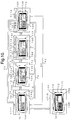
- Fig. 8 shows a cross-section of the pulse wave detection sensor unit mounted in electronic instrument 1 of this embodiment.
- component housing space 300 is formed by placing back lid 302 on the bottom side of sensor frame 36 which constitutes a casing body.
- Circuit board 35 is positioned inside component housing space 300.
- LED 31, phototransistor 32, and other electronic components are mounted on circuit board 35.
- One end of cable 20 is fastened to pulse wave detection sensor unit 30 by bushing 393, and various wires of cable 20 are soldered to various patterns on circuit board 35.
- pulse wave detection sensor unit 30 is attached to the finger such that cable 20 is extended from the base of the finger toward device main body 10.
- LED 31 and phototransistor 32 are arranged along the length of the finger, with LED 31 positioned on the finger tip side and phototransistor 32 positioned at the base of the finger. This configuration provides the effect of making it difficult for the ambient light to reach phototransistor 32.
- a light transmission window is formed by translucent plate 34 which is made of a glass plate on the upper area (actual pulse wave signal detection area) of sensor frame 36, and the light-emitting surface and light-receiving surface of LED 31 and phototransistor 32, respectively, are positioned by being oriented toward said translucent plate 34. Because of such a configuration, when a finger surface is pressed onto external surface 341 (surface that contacts the finger surface, or sensor surface) of translucent plate 34, LED 31 emits light toward the finger surface and phototransistor 32 can receive part of the light emitted by LED 31 that is reflected by the finger. Note that external surface 341 of translucent plate 34 protrudes farther than surrounding area 361 in order to improve its contact with the finger surface.
- an InGaN (indium-gallium-nitrogen) blue LED is used as LED 31, and its emission spectrum possesses a peak at 450 nm and its emission wavelength ranges from 350 to 600 nm.
- a GaAsP (gallium-arsenic-phosphorus) phototransistor is used as phototransistor 32, and the light-receiving wavelength of the element itself ranges from 300 to 600 nm, with some sensitive areas also at or below 300 nm.
- pulse wave detection sensor unit 30 in this embodiment When pulse wave detection sensor unit 30 in this embodiment is attached to the base of the finger by sensor-fastening strap 40 and light is emitted from LED 31 toward the finger, the light reaches blood vessels, and part of the light is absorbed by the hemoglobin in the blood and part of it is reflected.
- the light reflected by the finger (blood) is received by phototransistor 32, and the change in the amount of received light corresponds to the change in the blood volume (pulse wave in the blood). That is, the reflected light becomes weak when the blood volume is high and becomes strong when the blood volume is low. Therefore, pulse count, etc. can be measured by detecting the changes in the intensity of the reflected light.
- This embodiment uses LED 31 with an emission wavelength range of between 350 and 600 nm and phototransistor 32 with a light-receiving wavelength range of between 300 and 600 nm, and vital information is displayed based on the results taken in the overlapping wavelengths of between approximately 300 and approximately 600 nm, i.e., wavelengths of approximately 700 nm or shorter.
- pulse wave detection sensor unit 30 Even if the ambient light strikes the exposed part of the finger, lights with wavelengths of 700 nm or shorter contained in the ambient light do not use the finger as a light guide to reach phototransistor 32 (light-receiving area). The reason for this is as follows.
- the S/N ratio of the pulse wave signal based on blood volume change is high.
- the reason for this is as follows.
- the absorption coefficient of hemoglobin in the blood for lights with wavelengths of between 300 and 700 nm is several times to approximately one hundred or more times larger than the absorption coefficient for a light with wavelength of 800 nm which has been conventionally used as the detection light.
- lights with wavelengths of between 300 and 700 nm change sensitively to blood volume changes, producing higher pulse wave detection rate (S/N ratio) based on blood volume change.
- Fig. 9 schematically shows the configuration of pulse wave measuring area 55 which determines a pulse count, etc. based on the result input from pulse wave detection sensor unit 30.
- Pulse wave measuring area 55 first uses pulse wave signal conversion area 551 of control area 5 to amplify the signal input from pulse wave detection sensor unit 30 via cable 20, and then converts this signal to a digital signal and outputs it to pulse wave signal storage area 552 of RAM4.
- the pulse wave data temporarily stored in pulse wave signal storage area 552 is read by pulse wave signal computation area 553 of control area 5 and fast Fourier transformation (FFT processing) is applied to this data for frequency analysis.
- FFT processing fast Fourier transformation
- pulse wave component extraction area 554 The result of this analysis is input into pulse wave component extraction area 554, and this pulse wave component extraction area 554 then extracts pulse wave components from the signal input from pulse wave signal computation area 553 and outputs the result to pulse count computation area 555.
- This pulse count computation area 555 can then compute a pulse count from the frequency component of the pulse wave that was input and output the result to liquid crystal display device 13.
- portable electronic instrument 1 in this embodiment is provided with a clock function, a pulse wave measurement function as well as a pitch measurement function; and can be switched among the clock mode, the stopwatch mode, the pulse-counting mode in which both time and pulse wave information can be measured, as well as the pitch-measurement mode.
- Fig. 10 schematically shows the various modes available in portable electronic instrument 1 and the corresponding display contents of liquid crystal display device 13.
- Step ST11 shows the clock mode
- first segment display area 131 shows Monday, December 6, 1994
- second segment display area 132 shows the current time of 10:08:59 pm.
- Dot display area 134 shows "TIME” which indicates that the current mode is the clock mode.
- TIME will be displayed in dot display area 134 only for a few seconds immediately following the selection of the clock mode. Note that nothing is displayed in third segment display area 133.
- portable electronic instrument 1 in this embodiment can generate an alarm sound after one hour, for example; and any time can be set for this alarm generation time. If button switch 113 located in the 11 o'clock direction is pressed, the EL backlight of liquid crystal display device 13 is lit for 3 seconds and then automatically turns itself off.
- step ST12 the instrument switches to the running mode (step ST12).
- This mode is for using portable electronic instrument 1 as a stopwatch.
- the running mode the current time is displayed in first segment display area 131 before measurement is started (i.e., in the standby state), and [0:00′:00 ⁇ :00] is displayed in second segment display area 132.
- Dot display area 134 shows "RUN" which indicates the running mode for only 2 seconds and then the graphics change.
- step ST13 the instrument switches to the lap time recall mode (step ST13).
- This mode is for recalling lap times and split times measured in the past using portable electronic instrument 1.
- first segment display area 131 shows the date and second segment display area 132 shows the current time.
- Dot display area 134 shows "LAP/RECALL" which indicates the recall mode for only 2 seconds, and then the trend of pulse counts for the most recent lap will be displayed.
- step ST14 the instrument switches to the pulse wave measurement result recall mode (step ST14).
- This mode is for recalling the change in pulse count over time measured using portable electronic instrument 1 and stored during an event such as a marathon in the past, and the change in pitch over time measured in the past using portable electronic instrument 1.
- first segment display area 131 shows the date and second segment display area 132 shows the current time.
- Dot display area 134 shows "RESULT/RECALL" for only 2 seconds, and then a graph showing the change in the average pulse count over time will be displayed.
- step ST11 If button switch 112 located in the 4 o'clock direction is pressed again from this mode, the instrument returns to the clock mode (step ST11) as indicated by arrow P1. If nothing is entered in steps ST12 through ST14 for 10 minutes, the instrument also automatically returns to the clock mode (step ST11) as indicated by arrow P2.
- first segment display area 131 shows the date and second segment display area 132 shows the current time.
- dot display area 134 shows "TIME" indicating a return to the clock mode, as shown magnified in Fig. 11 (a). However, this display automatically goes off after 2 seconds as shown in Fig. 11 (b) and the normal state of the clock mode returns (step ST15). In this normal clock mode state, dot display area 134 does not show anything. That is, electrical power consumption is reduced by turning on the dot display for the minimum amount of time long enough to inform the user of the mode, and by using the fact that the dot display is not lit to indicate the normal state of the clock mode.
- the instrument When connector piece 80 is installed in connector area 70 of portable electronic instrument 1 of this embodiment in any of the states described above, the instrument automatically switches to the running mode (step ST12) as indicated by arrow P3 in Fig. 10. In this running mode, the instrument can function as a stopwatch and can also measure the pitch and pulse count during running.
- step ST31 when the instrument switches to the running mode which provides the pitch counter and pulse counter functions (step ST31), the current time is displayed in first segment display area 131 of the liquid crystal display device, [0:00′:00 ⁇ :00] is displayed in second segment display area 132, and dot display area 134 shows "RUN", as shown in Fig. 13 (a).
- a heart symbol also flashes in third segment display area 133, indicating that the instrument has been switched to the running mode which can provide the pitch counter and pulse counter functions.
- step ST34 When this mode switching occurs, electrical power is supplied to pulse wave measuring area 55, etc., and the initialization process such as setting of an operating frequency is carried out. Then, after 2 seconds, a pulse wave signal for measuring the initial pulse count is fetched.
- dot display area 134 alternates between the display of "STOP/5" (step ST32) and the display of "MOTION/4" (step ST33) at a 2 Hz frequency, and also shows a display that tells the user to hold still for 5 seconds. Note that the number displayed then changes by counting down 5 seconds. Then, the instrument stays in the standby state until button switch 117 located on the top side of surface of device main body 10 is pressed to begin time measurement (step ST34).
- dot display area 134 graphically displays the source waveform of a pulse wave signal as shown in Fig. 13 (b).
- the source waveform displayed here is the latest data. Therefore, by checking the shape and level of the source waveform of the pulse wave signal before beginning time measurement (a marathon), it is possible to determine whether or not LED31 and phototransistor 32 are correctly mounted. Also, by adjusting LED31 and phototransistor 32 while checking the shape and level of the source waveform, it is possible to position LED31 and phototransistor 32 in the optimum locations. Additionally, it is possible to check whether or not the ambient temperature and humidity in the environment are suitable to measurements beforehand. Furthermore, these functions can be used for testing portable electronic instrument 1 during its manufacture.
- third segment display area 132[??] displays the initial pulse count of "75" which is determined from pulse conversion.
- step ST35 when a marathon is started and at the same time button switch 117 located on the top side of the surface of device main body 10 is pressed, the measurement of the elapsed time begins and at the same time pitches and pulse counts are measured (step ST35).
- Fig. 14 (a) These measurement results are displayed as shown in Fig. 14 (a). That is, the elapsed time is displayed in second segment display area 132 and the change in the pulse count over time is graphically displayed in dot display area 134.
- This graphical display uses a bar graph that extends from the bottom toward the top, with the approximate mid point of the vertical axis set to a pulse count of 65.
- third segment display area 133 shows the scale for the vertical axis for the graph displayed in dot display area 134, as well as the current pulse count.
- the pulse count is graphically displayed as the difference from the preset reference pulse count (step ST36) as shown in Fig. 14 (b).
- the approximate mid point of the vertical axis is set to a pulse count of 150, for example, and the difference between this value and the actual pulse count is shown as a bar graph that extends up or down (in the positive or negative direction). Additionally, a mark indicating the specified pulse count range will be displayed at the right edge of dot display area 134.
- dot display area 134 will graphically display the change in pitch over time (step ST37).
- This graphical display uses a polygonal line graph, with the approximate mid point of the vertical axis set to a pitch of 170 (times/minute), for example, as shown in Fig. 14 (c).
- third segment display area 133 shows the scale (indicating that the approximate mid point of the vertical axis is 170) for the vertical axis for the graph displayed in dot display area 134, as well as the current pitch.
- portable electronic instrument 1 in this embodiment shows the change in pitch over time in dot display area 134 using a format, such as a polygonal line graph, different from that used for the pulse count display, the runner can easily recognize which information is currently being displayed by simply looking at the display format.
- Portable electronic instrument 1 of this embodiment does not have a switch for selecting a run or walk because it is designed to display an accurate pitch in either state.
- step ST36 From this state, if button switch 114 located in the 8 o'clock direction is pressed again, the instrument returns to the state in which dot display area 134 displays the change in pulse count over time (step ST36).
- step ST38 If the user presses button switch 116 located on the bottom side of the surface of device main body 10 when passing a designated point, the current lap time will be displayed in first segment display area 131 (step ST38). Then, after 10 seconds, the instrument automatically returns to step ST36.
- dot display area 134 will graphically display the change in pulse count over time after the goal-in as the pulse recovery characteristic (step ST40).
- the graphical display switches to a bar graph that extends from the bottom toward the top, with the same scale that has a pulse count of 150 as the approximate mid point of the vertical axis, as shown in Fig. 15 (a). Then, as shown in Fig. 15 (b), the recovery characteristic is measured for 2 minutes.
- third segment display area 133 shows the scale for the vertical axis for the graph displayed in dot display area 134, as well as the current pulse count.
- step ST41 if button switch 114 located in the 8 o'clock direction is pressed, dot display area 134 displays "PULSE/RESULT” for 1.5 seconds (step ST41), and then displays the change in pulse count over time for the most recent marathon (step ST42). If button switch 114 located in the 8 o'clock direction is pressed again, dot display area 134 displays "PITCH/RESULT” for 1.5 seconds (step ST43), and then displays the change in pitch over time for the most recent marathon (step ST44).
- dot display area 134 displays "COOLING/DOWN" for 1.5 seconds (step ST45), and then returns to the state (step ST40) in which the change in pulse count over time after the goal-in is displayed as the pulse recovery characteristic.
- dot display area 134 displays "PROTECT/MEMORY?” asking whether or not the current result should be saved (step ST46); and if "YES” response is given by pressing button switch 117 located on the top side of the surface of device main body 10, dot display area 134 displays "MEMORY” indicating that the result is being saved (step ST47), and returns to the initial state (step ST31) after 2 seconds.
- step ST13 If button switch 112 located in the 4 o'clock direction is pressed after measurements as a pitch counter and a pulse counter are finished, the instrument switches to the lap time recall mode (step ST13) as shown in Fig. 10. From this mode, if button switch 112 located in the 4 o'clock direction is pressed, the instrument switches to the pulse wave measurement result recall mode (step ST14). This mode can also graphically display the changes in pitch and pulse count over time in dot display area 134. From this state, if button switch 112 located in the 4 o'clock direction is pressed, the instrument returns to the clock mode (step ST11).
- first segment display area 133[??] again shows the date and second segment display area 132 shows the current time.
- Dot display area 134 shows "TIME” indicating a return to the clock mode, but this display automatically disappears after 2 seconds as indicated by arrow P4 and the normal state of the clock mode returns (step ST15).
- the portable electronic instrument of this embodiment is a device equipped with various types of displays and measurement functions, and can display various information such as lap, pulse, and pitch while the user is engaged in an activity such as a marathon.
- pitch measurement can be made with the operation of a single button, and furthermore no conditional setting such as for running or walking is required at all. Therefore, the user can display a pitch immediately when he/she wants to, and can instantly obtain a highly accurate pitch because no conditional setting such as for running or walking is required.
- the pitch measurement operation is not cumbersome, enabling the user to easily determine the condition of his/her body, as well as the state of the run or walk by displaying the pitch anytime.
- the third harmonic appears during walking and the second harmonic appears during running, as a high-level signal in the frequency range that is at or above the first frequency setting, e.g., 100 times/minute, when the frequency of a body movement signal is analyzed.
- the pitch measurement device, the electronic instrument, and the pitch measurement method according to the invention can automatically and accurately calculate pitch in either state. Therefore, the invention can accurately and quickly provide pitch both during running and walking, and can simply provide highly accurate pitches because it does not require any external operations for switching modes between running and walking or any analysis mode changes.
- whether the reference wave for which a pitch is to be determined is the second or third harmonic can be determined based on whether or not a high-level signal is present near a frequency that is 1/3 or 2/3 of the reference wave frequency, for example. Even when a high-level signal is present near a frequency that is 1/3 or 2/3 of the reference wave frequency, a configuration can be used that determines that the reference wave is the third harmonic only if the reference wave frequency is equal to or higher than the specified frequency level (the second frequency setting).
- the use of a measurement device and a measurement method capable of such double-checking can prevent noise from causing errors during the determination of whether the reference wave is the second or third harmonic, thus further increasing the accuracy of the pitch calculated.
- the pitch measurement device or the pitch measurement method according to the invention can easily provide pitch both during running and walking, they are suitable for incorporating a pitch measurement function in a multi-function electronic instrument such as that explained above, and accurate pitches can be obtained using simple operations even when various functions are being used.
- the present invention relates to a pitch measurement device and a pitch measurement method that measure pitch both during running and walking, and the invention makes it possible to calculate pitch without differentiating between running and walking. Therefore, a multi-function electronic instrument that includes a pitch measurement function can provide accurate pitches using simple operations and can prevent measurement errors.
Applications Claiming Priority (4)
| Application Number | Priority Date | Filing Date | Title |
|---|---|---|---|
| JP270394/95 | 1995-10-18 | ||
| JP27039495 | 1995-10-18 | ||
| JP7270394A JPH09114955A (ja) | 1995-10-18 | 1995-10-18 | ピッチ計 |
| PCT/JP1996/003032 WO1997015028A1 (fr) | 1995-10-18 | 1996-10-18 | Appareil de mesure de cadence, dispositif electronique et procede de mesure de cadence |
Publications (3)
| Publication Number | Publication Date |
|---|---|
| EP0805414A1 true EP0805414A1 (de) | 1997-11-05 |
| EP0805414A4 EP0805414A4 (de) | 1999-06-02 |
| EP0805414B1 EP0805414B1 (de) | 2002-06-05 |
Family
ID=17485655
Family Applications (1)
| Application Number | Title | Priority Date | Filing Date |
|---|---|---|---|
| EP96935371A Expired - Lifetime EP0805414B1 (de) | 1995-10-18 | 1996-10-18 | Schrittmessvorrichtung, elektronisches gerät und schrittmessverfahren |
Country Status (5)
| Country | Link |
|---|---|
| US (1) | US5908396A (de) |
| EP (1) | EP0805414B1 (de) |
| JP (1) | JPH09114955A (de) |
| DE (1) | DE69621594T2 (de) |
| WO (1) | WO1997015028A1 (de) |
Cited By (2)
| Publication number | Priority date | Publication date | Assignee | Title |
|---|---|---|---|---|
| EP1253404A2 (de) | 2001-04-23 | 2002-10-30 | Quentin Ladetto | In einem Koppelnavigationsmodus funktionierende Fussgängernavigationsverfahren und -vorrichtung |
| CN105492868A (zh) * | 2013-09-05 | 2016-04-13 | 高通股份有限公司 | 用于可靠运动分类的半步频率特性 |
Families Citing this family (30)
| Publication number | Priority date | Publication date | Assignee | Title |
|---|---|---|---|---|
| DE69833656T2 (de) | 1997-08-26 | 2006-08-17 | Seiko Epson Corp. | Vorrichtung zur diagnose von pulswellen |
| EP0941694B1 (de) * | 1997-09-05 | 2007-08-22 | Seiko Epson Corporation | Verfahren zur Konfiguration eines Sensors für reflektiertes Licht |
| US6527711B1 (en) * | 1999-10-18 | 2003-03-04 | Bodymedia, Inc. | Wearable human physiological data sensors and reporting system therefor |
| US7689437B1 (en) * | 2000-06-16 | 2010-03-30 | Bodymedia, Inc. | System for monitoring health, wellness and fitness |
| US8398546B2 (en) | 2000-06-16 | 2013-03-19 | Bodymedia, Inc. | System for monitoring and managing body weight and other physiological conditions including iterative and personalized planning, intervention and reporting capability |
| US6605038B1 (en) | 2000-06-16 | 2003-08-12 | Bodymedia, Inc. | System for monitoring health, wellness and fitness |
| US20060122474A1 (en) | 2000-06-16 | 2006-06-08 | Bodymedia, Inc. | Apparatus for monitoring health, wellness and fitness |
| IL153516A (en) | 2000-06-23 | 2007-07-24 | Bodymedia Inc | System for monitoring health, wellness and fitness |
| TWI264524B (en) * | 2002-02-25 | 2006-10-21 | Seiko Instr Inc | Pace measuring device |
| JP2003315085A (ja) * | 2002-02-25 | 2003-11-06 | Seiko Instruments Inc | ペース計測装置 |
| US7020508B2 (en) | 2002-08-22 | 2006-03-28 | Bodymedia, Inc. | Apparatus for detecting human physiological and contextual information |
| KR20050055072A (ko) | 2002-10-09 | 2005-06-10 | 보디미디어 인코퍼레이티드 | 인체의 생리 및 컨텍스츄얼 정보를 검출, 수신, 유도 및디스플레이하는 장치 |
| JP3801163B2 (ja) | 2003-03-07 | 2006-07-26 | セイコーエプソン株式会社 | 体動検出装置、ピッチ計、歩数計、腕時計型情報処理装置、制御方法及び制御プログラム |
| US7182738B2 (en) | 2003-04-23 | 2007-02-27 | Marctec, Llc | Patient monitoring apparatus and method for orthosis and other devices |
| US7341561B2 (en) * | 2003-05-30 | 2008-03-11 | Casio Computer Co., Ltd. | Wrist-worn high-accuracy pulsation measuring apparatus |
| JP5174348B2 (ja) | 2003-09-12 | 2013-04-03 | ボディーメディア インコーポレイテッド | 心臓関連状態パラメータのモニター方法及び装置 |
| JP5051767B2 (ja) | 2004-03-22 | 2012-10-17 | ボディーメディア インコーポレイテッド | 人間の状態パラメータをモニターするためのデバイス |
| US7503878B1 (en) | 2004-04-27 | 2009-03-17 | Performance Health Technologies, Inc. | Position monitoring device |
| US7658695B1 (en) | 2004-04-27 | 2010-02-09 | Performance Health Technologies, Inc. | Position monitoring displays |
| US7625316B1 (en) | 2004-04-27 | 2009-12-01 | Performance Health Technologies, Inc. | Position monitoring system |
| JP4885637B2 (ja) * | 2006-07-27 | 2012-02-29 | セイコーインスツル株式会社 | 腕装着型電子歩数計 |
| US20080319796A1 (en) * | 2007-02-16 | 2008-12-25 | Stivoric John M | Medical applications of lifeotypes |
| US10349844B2 (en) | 2012-01-16 | 2019-07-16 | Valencell, Inc. | Reduction of physiological metric error due to inertial cadence |
| WO2013109389A1 (en) | 2012-01-16 | 2013-07-25 | Valencell, Inc. | Physiological metric estimation rise and fall limiting |
| CN104969035B (zh) * | 2013-01-09 | 2019-05-10 | 瓦伦赛尔公司 | 基于惯性谐波的步调检测方法和系统 |
| CN103727959B (zh) * | 2013-12-31 | 2016-09-14 | 歌尔声学股份有限公司 | 计步方法及装置 |
| US9788794B2 (en) | 2014-02-28 | 2017-10-17 | Valencell, Inc. | Method and apparatus for generating assessments using physical activity and biometric parameters |
| US9449365B2 (en) | 2014-04-11 | 2016-09-20 | Fitbit, Inc. | Personalized scaling of graphical indicators |
| US9449409B2 (en) * | 2014-04-11 | 2016-09-20 | Fitbit, Inc. | Graphical indicators in analog clock format |
| CN108363595B (zh) * | 2017-01-26 | 2021-07-23 | 巨大机械工业股份有限公司 | 依骑乘状态而改变显示界面的自行车显示装置 |
Family Cites Families (12)
| Publication number | Priority date | Publication date | Assignee | Title |
|---|---|---|---|---|
| SU1326296A1 (ru) * | 1986-10-30 | 1987-07-30 | Всесоюзный Научно-Исследовательский Институт Физической Культуры | Устройство дл контрол техники бега |
| JP2552135B2 (ja) * | 1987-04-20 | 1996-11-06 | 松下電工株式会社 | 電子歩数計 |
| JPS63311586A (ja) * | 1987-06-15 | 1988-12-20 | Matsushita Electric Works Ltd | 電子歩数計 |
| US4962469A (en) * | 1988-04-18 | 1990-10-09 | Casio Computer Co., Ltd. | Exercise measuring instrument |
| JPH062098Y2 (ja) * | 1988-06-15 | 1994-01-19 | カシオ計算機株式会社 | 歩数計 |
| JPH02138369U (de) * | 1989-04-17 | 1990-11-19 | ||
| JPH0576502A (ja) * | 1991-09-20 | 1993-03-30 | Casio Comput Co Ltd | 電磁誘導通信システム |
| JP3220271B2 (ja) * | 1993-02-22 | 2001-10-22 | セイコーインスツルメンツ株式会社 | 脈拍計付歩数計 |
| JP2816944B2 (ja) * | 1993-12-20 | 1998-10-27 | セイコーインスツルメンツ株式会社 | 脈拍計 |
| CN1111499A (zh) * | 1994-02-03 | 1995-11-15 | 欧姆龙株式会社 | 脉搏计和脉搏计步器 |
| JP3610148B2 (ja) * | 1995-02-20 | 2005-01-12 | セイコーエプソン株式会社 | 周期・周波数計測装置 |
| US5583776A (en) * | 1995-03-16 | 1996-12-10 | Point Research Corporation | Dead reckoning navigational system using accelerometer to measure foot impacts |
-
1995
- 1995-10-18 JP JP7270394A patent/JPH09114955A/ja active Pending
-
1996
- 1996-10-18 US US08/849,872 patent/US5908396A/en not_active Expired - Lifetime
- 1996-10-18 EP EP96935371A patent/EP0805414B1/de not_active Expired - Lifetime
- 1996-10-18 WO PCT/JP1996/003032 patent/WO1997015028A1/ja active IP Right Grant
- 1996-10-18 DE DE69621594T patent/DE69621594T2/de not_active Expired - Lifetime
Non-Patent Citations (2)
| Title |
|---|
| DATABASE WPI Section PQ, Week 881010 March 1988 Derwent Publications Ltd., London, GB; Class P36, AN 88-069300 XP002099057 & SU 1 326 296 A (PHYS CULT RES IN) , 30 July 1987 * |
| See also references of WO9715028A1 * |
Cited By (4)
| Publication number | Priority date | Publication date | Assignee | Title |
|---|---|---|---|---|
| EP1253404A2 (de) | 2001-04-23 | 2002-10-30 | Quentin Ladetto | In einem Koppelnavigationsmodus funktionierende Fussgängernavigationsverfahren und -vorrichtung |
| EP1253404A3 (de) * | 2001-04-23 | 2009-02-18 | Ecole Polytechnique Federale De Lausanne (Epfl) | In einem Koppelnavigationsmodus funktionierende Fussgängernavigationsverfahren und -vorrichtung |
| CN105492868A (zh) * | 2013-09-05 | 2016-04-13 | 高通股份有限公司 | 用于可靠运动分类的半步频率特性 |
| CN105492868B (zh) * | 2013-09-05 | 2018-06-26 | 高通股份有限公司 | 用于可靠运动分类的半步频率特性 |
Also Published As
| Publication number | Publication date |
|---|---|
| DE69621594D1 (de) | 2002-07-11 |
| US5908396A (en) | 1999-06-01 |
| WO1997015028A1 (fr) | 1997-04-24 |
| DE69621594T2 (de) | 2002-09-19 |
| EP0805414B1 (de) | 2002-06-05 |
| JPH09114955A (ja) | 1997-05-02 |
| EP0805414A4 (de) | 1999-06-02 |
Similar Documents
| Publication | Publication Date | Title |
|---|---|---|
| EP0805414B1 (de) | Schrittmessvorrichtung, elektronisches gerät und schrittmessverfahren | |
| US5776070A (en) | Pulse rate counter utilizing body movement amptitude detection | |
| JP3755501B2 (ja) | 脈拍計、脈拍計の制御方法、時計型情報機器、制御プログラムおよび記録媒体 | |
| US6099478A (en) | Pulse counter and pulse display method | |
| JP3584143B2 (ja) | 脈波検出装置および脈拍計 | |
| US5759156A (en) | Period and frequency measurement device with correction device and method thereof | |
| US6023662A (en) | Measurement device, portable electronic instrument, and measurement method | |
| JP2004081745A (ja) | ピッチ計、ピッチ計の制御方法、腕時計型情報処理装置、制御プログラムおよび記録媒体 | |
| JP3420409B2 (ja) | 計測装置 | |
| JP5790694B2 (ja) | 生体情報処理方法、及び生体情報処理装置 | |
| JP3481747B2 (ja) | 計測装置 | |
| JP5239370B2 (ja) | 生体情報処理装置、及び、生体情報処理方法 | |
| JP3468390B2 (ja) | 携帯用脈波計測装置における計測結果の表示方法 | |
| JP3558428B2 (ja) | 生体情報計測装置 | |
| JP3476979B2 (ja) | 携帯用電子機器 | |
| EP0800090A1 (de) | Verbindungsprüfungsvorrichtung und -verfahren sowie tragbares elektronisches gerät dazu | |
| JP3415971B2 (ja) | 計測装置 | |
| JP5071148B2 (ja) | 生体情報処理装置、及び、生体情報処理装置の制御方法 | |
| JP3492044B2 (ja) | 脈波計測装置における表示方法、及び脈波計測装置 | |
| JP2005137677A (ja) | 計測装置、計測装置の制御方法、制御プログラムおよび記録媒体 | |
| JPH09135818A (ja) | 携帯用電子機器 | |
| JPH0968581A (ja) | 携帯用電子機器におけるモード案内方法 |
Legal Events
| Date | Code | Title | Description |
|---|---|---|---|
| PUAI | Public reference made under article 153(3) epc to a published international application that has entered the european phase |
Free format text: ORIGINAL CODE: 0009012 |
|
| AK | Designated contracting states |
Kind code of ref document: A1 Designated state(s): DE FI FR GB |
|
| 17P | Request for examination filed |
Effective date: 19971022 |
|
| A4 | Supplementary search report drawn up and despatched |
Effective date: 19990416 |
|
| AK | Designated contracting states |
Kind code of ref document: A4 Designated state(s): DE FI FR GB |
|
| GRAG | Despatch of communication of intention to grant |
Free format text: ORIGINAL CODE: EPIDOS AGRA |
|
| 17Q | First examination report despatched |
Effective date: 20010808 |
|
| GRAG | Despatch of communication of intention to grant |
Free format text: ORIGINAL CODE: EPIDOS AGRA |
|
| GRAH | Despatch of communication of intention to grant a patent |
Free format text: ORIGINAL CODE: EPIDOS IGRA |
|
| RIN1 | Information on inventor provided before grant (corrected) |
Inventor name: NAKAMURA, CHIAKI Inventor name: HAYAKAWA, MOTOMU |
|
| GRAH | Despatch of communication of intention to grant a patent |
Free format text: ORIGINAL CODE: EPIDOS IGRA |
|
| GRAA | (expected) grant |
Free format text: ORIGINAL CODE: 0009210 |
|
| AK | Designated contracting states |
Kind code of ref document: B1 Designated state(s): DE FI FR GB |
|
| REG | Reference to a national code |
Ref country code: GB Ref legal event code: FG4D |
|
| REF | Corresponds to: |
Ref document number: 69621594 Country of ref document: DE Date of ref document: 20020711 |
|
| ET | Fr: translation filed | ||
| PLBE | No opposition filed within time limit |
Free format text: ORIGINAL CODE: 0009261 |
|
| STAA | Information on the status of an ep patent application or granted ep patent |
Free format text: STATUS: NO OPPOSITION FILED WITHIN TIME LIMIT |
|
| 26N | No opposition filed |
Effective date: 20030306 |
|
| REG | Reference to a national code |
Ref country code: DE Ref legal event code: R082 Ref document number: 69621594 Country of ref document: DE Representative=s name: WEICKMANN & WEICKMANN PATENTANWAELTE - RECHTSA, DE Effective date: 20140724 Ref country code: DE Ref legal event code: R082 Ref document number: 69621594 Country of ref document: DE Representative=s name: PATENTANWAELTE WEICKMANN & WEICKMANN, DE Effective date: 20140724 Ref country code: DE Ref legal event code: R081 Ref document number: 69621594 Country of ref document: DE Owner name: SEIKO EPSON CORP., JP Free format text: FORMER OWNERS: SEIKO EPSON CORP., TOKYO, JP; SEIKO INSTRUMENTS INC., CHIBA, JP Effective date: 20140724 Ref country code: DE Ref legal event code: R081 Ref document number: 69621594 Country of ref document: DE Owner name: SEIKO EPSON CORP., JP Free format text: FORMER OWNER: SEIKO EPSON CORP., SEIKO INSTRUMENTS INC., , JP Effective date: 20140724 |
|
| REG | Reference to a national code |
Ref country code: GB Ref legal event code: 732E Free format text: REGISTERED BETWEEN 20140814 AND 20140820 |
|
| REG | Reference to a national code |
Ref country code: FR Ref legal event code: TP Owner name: SEIKO EPSON CORPORATION, JP Effective date: 20141118 |
|
| REG | Reference to a national code |
Ref country code: FR Ref legal event code: PLFP Year of fee payment: 20 |
|
| PGFP | Annual fee paid to national office [announced via postgrant information from national office to epo] |
Ref country code: FR Payment date: 20150908 Year of fee payment: 20 |
|
| PGFP | Annual fee paid to national office [announced via postgrant information from national office to epo] |
Ref country code: GB Payment date: 20151014 Year of fee payment: 20 Ref country code: DE Payment date: 20151013 Year of fee payment: 20 Ref country code: FI Payment date: 20151012 Year of fee payment: 20 |
|
| REG | Reference to a national code |
Ref country code: DE Ref legal event code: R071 Ref document number: 69621594 Country of ref document: DE |
|
| REG | Reference to a national code |
Ref country code: GB Ref legal event code: PE20 Expiry date: 20161017 |
|
| PG25 | Lapsed in a contracting state [announced via postgrant information from national office to epo] |
Ref country code: GB Free format text: LAPSE BECAUSE OF EXPIRATION OF PROTECTION Effective date: 20161017 |