EP0805316B1 - Accumulateur à eau chaude avec un récipient intérieur - Google Patents
Accumulateur à eau chaude avec un récipient intérieur Download PDFInfo
- Publication number
- EP0805316B1 EP0805316B1 EP97107299A EP97107299A EP0805316B1 EP 0805316 B1 EP0805316 B1 EP 0805316B1 EP 97107299 A EP97107299 A EP 97107299A EP 97107299 A EP97107299 A EP 97107299A EP 0805316 B1 EP0805316 B1 EP 0805316B1
- Authority
- EP
- European Patent Office
- Prior art keywords
- hot water
- vessel
- water cylinder
- conical component
- funnel
- Prior art date
- Legal status (The legal status is an assumption and is not a legal conclusion. Google has not performed a legal analysis and makes no representation as to the accuracy of the status listed.)
- Expired - Lifetime
Links
Images


Classifications
-
- F—MECHANICAL ENGINEERING; LIGHTING; HEATING; WEAPONS; BLASTING
- F24—HEATING; RANGES; VENTILATING
- F24H—FLUID HEATERS, e.g. WATER OR AIR HEATERS, HAVING HEAT-GENERATING MEANS, e.g. HEAT PUMPS, IN GENERAL
- F24H1/00—Water heaters, e.g. boilers, continuous-flow heaters or water-storage heaters
- F24H1/18—Water-storage heaters
- F24H1/181—Construction of the tank
-
- F—MECHANICAL ENGINEERING; LIGHTING; HEATING; WEAPONS; BLASTING
- F24—HEATING; RANGES; VENTILATING
- F24H—FLUID HEATERS, e.g. WATER OR AIR HEATERS, HAVING HEAT-GENERATING MEANS, e.g. HEAT PUMPS, IN GENERAL
- F24H1/00—Water heaters, e.g. boilers, continuous-flow heaters or water-storage heaters
- F24H1/18—Water-storage heaters
- F24H1/20—Water-storage heaters with immersed heating elements, e.g. electric elements or furnace tubes
- F24H1/201—Water-storage heaters with immersed heating elements, e.g. electric elements or furnace tubes using electric energy supply
- F24H1/202—Water-storage heaters with immersed heating elements, e.g. electric elements or furnace tubes using electric energy supply with resistances
Definitions
- the present invention relates to a hot water tank with an inner container, the two opposite longitudinal side walls and two transverse side walls connected to these having either the two opposite Long side walls or the two opposite Transverse sidewalls preferably in one with respect to the height of the container and the width of the container mean Area drawn in towards the center of the container are, the area drawn in towards the center of the container the long side walls or the transverse side walls on both sides has the shape of a funnel or cone and the funnel bottoms of the two funnels in the Place the center of the container together and face each other support and with the two adjacent Hopper bottoms of the inner container each have at least one Have through hole.
- a hot water tank of the above type, of which the Invention based is known from WO 95/08085 A.
- the Long side walls form funnel-shaped indentations here.
- the Hopper bottoms of the feeders support each other and are connected with a screw that goes into the through hole is plugged in.
- different functional parts are necessary, which must be installed in or on the hot water tank, For example, the control group with control device for the Setting the desired heating temperature.
- the present invention is based on the object a hot water tank with an inner container at the beginning to create the genus mentioned, in which the said Assemblies for the control and setting of the desired Temperature are easy to assemble and space-saving that can.
- a hot water tank provides the solution to this task with an inner container of the type mentioned with the characteristic features of the main claim.
- the invention Solution takes advantage of the fact that for stability reasons the inner container in about
- a conical component is used and over a Fastener that is received by the through hole is attached to the funnel bottom.
- the component will then be further for the Function of the hot water tank attached necessary components.
- these mounting parts are preferred those with an electrical / electronic assembly for the regulation and setting of the desired heating temperature in association with.
- Hot water tanks of this type usually point to the Inner containers around and have insulation as well an outer container that serves the assemblies and the To protect and disguise the inner container from the outside.
- the minimum size of the entire hot water tank is through the volume of the inner container and the Thermal insulation necessary layer thickness of the insulation given and in this construction volume, if possible, all also necessary assemblies of the hot water tank space to have.
- the size optimized from this point of view is the size optimized from this point of view.
- Attachment of the electrical / electronic component and optionally further components on the conical Component can be plugged onto this in the outer area Washer is provided. This can be done on this disc electrical / electronic component and optionally other components can be determined. You can do that conical component also use the outer container of the hot water tank on the inner tank.
- Said electrical / electronic component comprises preferably a controller and a thermostat.
- a rotatable control element used with the electrical / electronic component is in operative connection and that on the conical Component for example by means of this on the outside Area attachable disc is definable.
- This control element is of course usually on the Arranged outside of the outer container while the Regulation and the thermostat on the inside of the Outer container.
- the control element is preferred arranged rotatably about an axis which is the central axis of the conical component corresponds.
- the conical Component is z. B. via a Screw or the like through the through hole of the grips both adjacent funnel bottoms, on Inner container set.
- the cone shape of the conical component has the sense that this is adapted to the shape of the funnel of the inner container and the conical component is supported on the inner container.
- the outer peripheral area of the conical Component for attaching z. B. used a disc become. This enables a pre-assembly, namely the Control module, the thermostat etc.
- the disc can be mounted and then the disc can simply be opened the conical component can be plugged on, so that the Assembly takes place quickly.
- an axis of the control assembly present through the disc protrudes outwards, preferably through an opening of the Outer container so that after putting on the Outer container, the control element z. B. by molded Locking elements or the like on this axis of Control module can be simply plugged on.
- the aforementioned conical component which in one of the Funnel of the inner container is not necessary have a continuous cone jacket, but can e.g. B. like this be designed so that it is distributed over the circumference Has webs that this component give conical outline, with several such webs at one end or at both ends with each other are connected and smaller or between these webs there are larger openings. For example one has a conical component with four such webs use, then the webs on the walls of the Support the funnel of the inner container. If the webs in the Area of the tip of the conical component connected there is a sufficient abutment for one Fastening element for attachment to the funnel bottom. On the outside, the disc can be on the ends of the webs be put on. Those following the shape of the cone shell Bridges can be at their outer end by a stabilizing ring web to be connected.
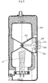
- the inner container 30 for a hot water tank has channels formed on the inner container for the water inlet and outlet in the upper area a drain channel 28 for the hot water and next to it arranged an inlet channel 27 for the incoming Cold water.
- This inlet channel, 27 opens into another Channel 26, which is guided along the container 30 to Bottom of the container where it is deflected by 90 ° and then opens approximately horizontally into the inner container 30.
- the Cold water gets into the inner container there, heated in this and leaves the container as warm water via the channel 28 formed above.
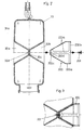
- the basic shape of the inner container 30 is derived from that of a cuboid and has the inner container 30 an approximately rectangular outline with something rounded corner transition areas 33.
- the container shape deviates from a cuboid or box shape than as the two longitudinal side walls 31a, 31b, which by the two transverse side walls 32a, 32b are connected to one another, in an approximately central area are drawn inwards such that there are two opposite funnels 20a, 20b result, which extend to the middle so far that the Funnel bottoms 20c lie next to each other and in the Support the area of the circular contact surface.
- the Both funnel bottoms have a through hole 20d here on so that you can attach mounting parts here for certain functions of the hot water tank are required, as explained below using an example.
- the inner container 30 has an opening 42 in the lower region, which is arranged off-center on one side and one has a circular outline.
- This opening 42 serves a Heating coil through this opening into the inner container 30 introduce. Because the heating coil is off-center in introduces the inner container 30, there will be better circulation of the hot water in the inner tank.
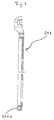
- Fig. 2 shows in a Exploded view of a conical component 200, the adapted in its outer shape to that of the funnel 20b is.
- This conical component 200 has four over the Circumferentially distributed on one side of the component 200 tapered webs 200a, which on the outside of the conical component 200 by a Ring web 200b are interconnected.
- the four webs 200a are closed connected to a kind of truncated cone 200c.
- This truncated cone 200c has a bore 200d so that a driving pin 201 or a similar fastener through this hole 200d and pass the hole 20d in the funnel bottom 20c can to the conical component 200 on the inner container 30th to attach as shown in Fig. 3.
- FIGS. 4 and 5 It can be seen here that the inner container 30 is insulated 300 is embedded and this in turn by one Outer container 205 is enclosed, the inner container 30th disguised and an almost cuboid box shape Has.
- the heating coil 41 can also be seen in FIGS. which are inserted into the circular opening 42 of the inner container 30 is.
- the conical component 200 takes in its interior in the outer area a control unit 202 with thermostat on the disc 203 on the other Is attached inside. This disc 203 is again on Provide circumference with webs and with these webs on the Web 200a and the ring web 200b of the conical Component 200 placed and thus attached to it.
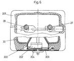
- Fig. 6 shows again the top view of the outer container 205 for the hot water tank according to the 4 and 5, this outer container 205 partially is cut open so that the inner container 30 can be seen can and the conical member 200 that is in the funnel 20b of the inner container 30 is inserted.
- the control unit 202 which on the conical component 200 attached disc 203 and that rotatable control element 204. You can also see that from the Outer container 205 upwards emerging connections for the drain channel 28 and the inlet channel 27.
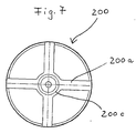
- the conical component 200 is in FIGS. 2 and 3 in the Cut recognizable. For a better understanding is in Fig. 7 another view of this conical component 200 in Direction of its axis viewed. One recognises the four webs 200a and the truncated cone 200c.
Landscapes
- Engineering & Computer Science (AREA)
- General Engineering & Computer Science (AREA)
- Chemical & Material Sciences (AREA)
- Thermal Sciences (AREA)
- Combustion & Propulsion (AREA)
- Mechanical Engineering (AREA)
- Physics & Mathematics (AREA)
- Cookers (AREA)
- Domestic Hot-Water Supply Systems And Details Of Heating Systems (AREA)
- Devices For Dispensing Beverages (AREA)
- Details Of Fluid Heaters (AREA)
- Devices For Medical Bathing And Washing (AREA)
- Standing Axle, Rod, Or Tube Structures Coupled By Welding, Adhesion, Or Deposition (AREA)
Claims (6)
- Chauffe-eau à accumulation comprenant un réservoir intérieur (30) qui comporte deux parois latérales longitudinales opposées (31a, 31b) et, reliées à celles-ci, deux parois latérales transversales (32a, 32b), soit les deux parois latérales longitudinales opposées (31a, 31b) soit les deux parois latérales transversales opposées (32a, 32b) étant de préférence rétreintes vers l'intérieur en direction du centre du réservoir dans une zone centrale par rapport à la hauteur du réservoir et à la largeur du réservoir, la zone des parois latérales longitudinales (31a, 31b) ou des parois latérales transversales (32a, 32b) rétreinte vers le centre du réservoir présentant sur chacun des deux côtés sensiblement la forme d'un entonnoir ou d'un cône, et les fonds d'entonnoirs (20c) des deux entonnoirs respectifs (20a, 20b) étant accolés au centre du réservoir et prenant appui à plat l'un contre l'autre, les deux fonds d'entonnoirs accolés (20c) du réservoir intérieur (30) étant chacun pourvus d'au moins un orifice débouchant (20d), caractérisé en ce qu'un élément structurel conique (200) est disposé dans au moins un des deux entonnoirs (20a, 20b) et est fixé au fond d'entonnoir (20c) par un élément de fixation (201) traversant l'orifice débouchant (20d).
- Chauffe-eau à accumulation selon la revendication 1, caractérisé en ce que l'élément structurel conique (200) forme un logement qui reçoit au moins un composant électrique/électronique (202), lequel est fixé à l'élément structurel conique (200) par des moyens appropriés (203).
- Chauffe-eau à accumulation selon la revendication 2, caractérisé en ce que, pour la fixation de l'élément structurel électrique/électronique (202) et, le cas échéant, d'autres éléments structurels à l'élément structurel conique (200), il est prévu un disque (203) emboítable sur celui-ci dans la zone extérieure.
- Chauffe-eau à accumulation selon l'une des revendications 1 à 3, caractérisé en ce qu'un réservoir extérieur (205) du chauffe-eau à accumulation est fixé au réservoir intérieur par l'intermédiaire de l'élément structurel conique (200).
- Chauffe-eau à accumulation selon la revendication 4, caractérisé en ce qu'il est prévu un élément de manoeuvre (204) monté tournant autour d'un axe sur le côté extérieur du réservoir extérieur (205), ledit axe correspondant à l'axe médian (206) de l'élément structurel conique (200), et l'élément de manoeuvre (204) étant en liaison active avec l'élément structurel électrique/électronique (202) logé dans l'élément structurel conique (200).
- Chauffe-eau à accumulation selon la revendication 5, caractérisé en ce que l'élément structurel électrique/électronique (202) comprend un moyen de régulation et un thermostat, et l'élément de manoeuvre (204) sert à régler la température de chauffage souhaitée du chauffe-eau à accumulation.
Applications Claiming Priority (2)
| Application Number | Priority Date | Filing Date | Title |
|---|---|---|---|
| DE19617741 | 1996-05-03 | ||
| DE19617741 | 1996-05-03 |
Publications (3)
| Publication Number | Publication Date |
|---|---|
| EP0805316A2 EP0805316A2 (fr) | 1997-11-05 |
| EP0805316A3 EP0805316A3 (fr) | 1998-11-04 |
| EP0805316B1 true EP0805316B1 (fr) | 2001-10-24 |
Family
ID=7793212
Family Applications (1)
| Application Number | Title | Priority Date | Filing Date |
|---|---|---|---|
| EP97107299A Expired - Lifetime EP0805316B1 (fr) | 1996-05-03 | 1997-05-02 | Accumulateur à eau chaude avec un récipient intérieur |
Country Status (4)
| Country | Link |
|---|---|
| EP (1) | EP0805316B1 (fr) |
| AT (1) | ATE207602T1 (fr) |
| DE (2) | DE59705030D1 (fr) |
| ES (1) | ES2162151T3 (fr) |
Families Citing this family (6)
| Publication number | Priority date | Publication date | Assignee | Title |
|---|---|---|---|---|
| GB2347991B (en) * | 1999-03-16 | 2002-10-02 | Elsy & Gibbons Ltd | Hot water supply appliance |
| DE102004020820A1 (de) * | 2004-04-28 | 2005-12-22 | BSH Bosch und Siemens Hausgeräte GmbH | Wasserbehälter eines Wasserbereiters, insbesondere eines Wasserspeichers |
| DE102005062660B4 (de) * | 2005-12-23 | 2023-10-26 | Stiebel Eltron Gmbh & Co. Kg | Warmwasserbereiter sowie Grundbehälter für einen Warmwasserbereiter |
| DE102005063542B3 (de) * | 2005-12-23 | 2024-08-08 | Stiebel Eltron Gmbh & Co. Kg | Warmwasserbereiter sowie Grundbehälter für einen Warmwasserbereiter |
| CN103162444B (zh) * | 2011-12-08 | 2014-11-05 | 刘威良 | 热水器储水箱 |
| DE102020100807A1 (de) * | 2020-01-15 | 2021-07-15 | Stiebel Eltron Gmbh & Co. Kg | Kleinwarmwasserspeicher mit nebeneinander angeordneten Speicheranschlüssen |
Family Cites Families (3)
| Publication number | Priority date | Publication date | Assignee | Title |
|---|---|---|---|---|
| DE1288279C2 (de) * | 1963-08-13 | 1973-02-01 | Siemens Ag | Wasserbehaelter fuer elektrische Heisswasserbereiter |
| DE3011426A1 (de) * | 1980-03-25 | 1981-10-01 | Schneider, Helmhold, 5230 Altenkirchen | Kunststoff-waermespeicher, insbesondere fuer die warmwasserspeicherung im haustechnischen bereich u.dgl., sowie verfahren zu seiner hertellung |
| IT1261870B (it) * | 1993-09-17 | 1996-06-03 | Romano Nardi | Scaldaacqua autoportante, atto ad essere costituito in materiale plastico. |
-
1997
- 1997-05-02 DE DE59705030T patent/DE59705030D1/de not_active Expired - Fee Related
- 1997-05-02 DE DE19718354A patent/DE19718354A1/de not_active Withdrawn
- 1997-05-02 AT AT97107299T patent/ATE207602T1/de not_active IP Right Cessation
- 1997-05-02 EP EP97107299A patent/EP0805316B1/fr not_active Expired - Lifetime
- 1997-05-02 ES ES97107299T patent/ES2162151T3/es not_active Expired - Lifetime
Also Published As
| Publication number | Publication date |
|---|---|
| EP0805316A2 (fr) | 1997-11-05 |
| ATE207602T1 (de) | 2001-11-15 |
| DE19718354A1 (de) | 1997-11-06 |
| ES2162151T3 (es) | 2001-12-16 |
| EP0805316A3 (fr) | 1998-11-04 |
| DE59705030D1 (de) | 2001-11-29 |
Similar Documents
| Publication | Publication Date | Title |
|---|---|---|
| DE3043422C2 (fr) | ||
| DE60022787T2 (de) | Mehrwegventil | |
| DE3905655C2 (de) | Steuervorrichtung | |
| EP0805316B1 (fr) | Accumulateur à eau chaude avec un récipient intérieur | |
| EP0866300A2 (fr) | Refroidisseur d'huile de transmission | |
| DE1912905C3 (de) | Korrosionsbeständiger Kegelhahn | |
| AT8713U1 (de) | Plattenheizkörper für die kombinierte heizung | |
| DE3234432A1 (de) | Beleuchtungseinrichtung | |
| DE29511076U1 (de) | Heizkörperanordnung | |
| DE3422336C2 (fr) | ||
| AT393154B (de) | Zum vermischen von warmwasser und kaltwasser dienendes mischventil | |
| CH371154A (de) | Poldurchführung im Zellendeckel eines Akkumulators, insbesondere eines Bleiakkumulators | |
| DE8706453U1 (de) | Mischhahn für Warm- und Kaltwasser | |
| AT412991B (de) | Verteilerventil | |
| EP1760407A1 (fr) | Distributeur pour système de chauffage et de refroidissement | |
| DE3416335A1 (de) | Drehschieberventil | |
| AT404299B (de) | Anschlussgarnitur | |
| DE4302264C2 (de) | Tauchbadgerät | |
| DE69612530T2 (de) | Rohrradiator | |
| DE19843694C2 (de) | Innenbehälter für Heißwasserspeicher mit einem Überströmkanal | |
| DE2910833A1 (de) | Ventilanordnung mit einem thermostatventil | |
| DE1600995B2 (de) | Wahlweise fuer links- oder rechtsanschluss verwendbarer mehrweg-mischhahn | |
| DE19638939C1 (de) | Anordnung zur Zu- und Abführung eines Heizmediums zu bzw. von einem Gliederheizkörper | |
| DE20108117U1 (de) | Grundkörper, vorzugsweise als Komponente eines elektrischen Durchlauferhitzers | |
| EP0666440A1 (fr) | Tiroir rotatif d'affluence et de refluement pour radiateurs de chauffage |
Legal Events
| Date | Code | Title | Description |
|---|---|---|---|
| PUAI | Public reference made under article 153(3) epc to a published international application that has entered the european phase |
Free format text: ORIGINAL CODE: 0009012 |
|
| AK | Designated contracting states |
Kind code of ref document: A2 Designated state(s): AT BE CH DE ES FR GB LI LU NL |
|
| PUAL | Search report despatched |
Free format text: ORIGINAL CODE: 0009013 |
|
| AK | Designated contracting states |
Kind code of ref document: A3 Designated state(s): AT BE CH DE ES FR GB LI LU NL |
|
| 17P | Request for examination filed |
Effective date: 19981124 |
|
| 17Q | First examination report despatched |
Effective date: 20000306 |
|
| GRAG | Despatch of communication of intention to grant |
Free format text: ORIGINAL CODE: EPIDOS AGRA |
|
| GRAG | Despatch of communication of intention to grant |
Free format text: ORIGINAL CODE: EPIDOS AGRA |
|
| GRAH | Despatch of communication of intention to grant a patent |
Free format text: ORIGINAL CODE: EPIDOS IGRA |
|
| GRAH | Despatch of communication of intention to grant a patent |
Free format text: ORIGINAL CODE: EPIDOS IGRA |
|
| RAP1 | Party data changed (applicant data changed or rights of an application transferred) |
Owner name: FRANZ KALDEWEI GMBH & CO.KG |
|
| GRAA | (expected) grant |
Free format text: ORIGINAL CODE: 0009210 |
|
| AK | Designated contracting states |
Kind code of ref document: B1 Designated state(s): AT BE CH DE ES FR GB LI LU NL |
|
| REF | Corresponds to: |
Ref document number: 207602 Country of ref document: AT Date of ref document: 20011115 Kind code of ref document: T |
|
| REG | Reference to a national code |
Ref country code: CH Ref legal event code: EP |
|
| REG | Reference to a national code |
Ref country code: CH Ref legal event code: NV Representative=s name: KELLER & PARTNER PATENTANWAELTE AG |
|
| REF | Corresponds to: |
Ref document number: 59705030 Country of ref document: DE Date of ref document: 20011129 |
|
| REG | Reference to a national code |
Ref country code: ES Ref legal event code: FG2A Ref document number: 2162151 Country of ref document: ES Kind code of ref document: T3 |
|
| REG | Reference to a national code |
Ref country code: GB Ref legal event code: IF02 |
|
| GBT | Gb: translation of ep patent filed (gb section 77(6)(a)/1977) |
Effective date: 20020105 |
|
| PGFP | Annual fee paid to national office [announced via postgrant information from national office to epo] |
Ref country code: DE Payment date: 20020304 Year of fee payment: 6 |
|
| ET | Fr: translation filed | ||
| PGFP | Annual fee paid to national office [announced via postgrant information from national office to epo] |
Ref country code: AT Payment date: 20020409 Year of fee payment: 6 |
|
| PGFP | Annual fee paid to national office [announced via postgrant information from national office to epo] |
Ref country code: FR Payment date: 20020411 Year of fee payment: 6 |
|
| PGFP | Annual fee paid to national office [announced via postgrant information from national office to epo] |
Ref country code: NL Payment date: 20020415 Year of fee payment: 6 Ref country code: LU Payment date: 20020415 Year of fee payment: 6 |
|
| PGFP | Annual fee paid to national office [announced via postgrant information from national office to epo] |
Ref country code: CH Payment date: 20020416 Year of fee payment: 6 |
|
| PGFP | Annual fee paid to national office [announced via postgrant information from national office to epo] |
Ref country code: GB Payment date: 20020417 Year of fee payment: 6 |
|
| PGFP | Annual fee paid to national office [announced via postgrant information from national office to epo] |
Ref country code: BE Payment date: 20020508 Year of fee payment: 6 |
|
| PGFP | Annual fee paid to national office [announced via postgrant information from national office to epo] |
Ref country code: ES Payment date: 20020510 Year of fee payment: 6 |
|
| PLBE | No opposition filed within time limit |
Free format text: ORIGINAL CODE: 0009261 |
|
| STAA | Information on the status of an ep patent application or granted ep patent |
Free format text: STATUS: NO OPPOSITION FILED WITHIN TIME LIMIT |
|
| 26N | No opposition filed | ||
| PG25 | Lapsed in a contracting state [announced via postgrant information from national office to epo] |
Ref country code: LU Free format text: LAPSE BECAUSE OF NON-PAYMENT OF DUE FEES Effective date: 20030502 Ref country code: GB Free format text: LAPSE BECAUSE OF NON-PAYMENT OF DUE FEES Effective date: 20030502 Ref country code: AT Free format text: LAPSE BECAUSE OF NON-PAYMENT OF DUE FEES Effective date: 20030502 |
|
| PG25 | Lapsed in a contracting state [announced via postgrant information from national office to epo] |
Ref country code: ES Free format text: LAPSE BECAUSE OF NON-PAYMENT OF DUE FEES Effective date: 20030503 |
|
| PG25 | Lapsed in a contracting state [announced via postgrant information from national office to epo] |
Ref country code: LI Free format text: LAPSE BECAUSE OF NON-PAYMENT OF DUE FEES Effective date: 20030531 Ref country code: CH Free format text: LAPSE BECAUSE OF NON-PAYMENT OF DUE FEES Effective date: 20030531 Ref country code: BE Free format text: LAPSE BECAUSE OF NON-PAYMENT OF DUE FEES Effective date: 20030531 |
|
| BERE | Be: lapsed |
Owner name: FRANZ *KALDEWEI G.M.B.H. & CO. K.G. Effective date: 20030531 |
|
| PG25 | Lapsed in a contracting state [announced via postgrant information from national office to epo] |
Ref country code: NL Free format text: LAPSE BECAUSE OF NON-PAYMENT OF DUE FEES Effective date: 20031201 |
|
| PG25 | Lapsed in a contracting state [announced via postgrant information from national office to epo] |
Ref country code: DE Free format text: LAPSE BECAUSE OF NON-PAYMENT OF DUE FEES Effective date: 20031202 |
|
| GBPC | Gb: european patent ceased through non-payment of renewal fee |
Effective date: 20030502 |
|
| REG | Reference to a national code |
Ref country code: CH Ref legal event code: PL |
|
| PG25 | Lapsed in a contracting state [announced via postgrant information from national office to epo] |
Ref country code: FR Free format text: LAPSE BECAUSE OF NON-PAYMENT OF DUE FEES Effective date: 20040130 |
|
| NLV4 | Nl: lapsed or anulled due to non-payment of the annual fee |
Effective date: 20031201 |
|
| REG | Reference to a national code |
Ref country code: FR Ref legal event code: ST |
|
| REG | Reference to a national code |
Ref country code: ES Ref legal event code: FD2A Effective date: 20030503 |