EP0804654B1 - Regelvorrichtung für eine wasserversorgungsanlage - Google Patents
Regelvorrichtung für eine wasserversorgungsanlage Download PDFInfo
- Publication number
- EP0804654B1 EP0804654B1 EP96903962A EP96903962A EP0804654B1 EP 0804654 B1 EP0804654 B1 EP 0804654B1 EP 96903962 A EP96903962 A EP 96903962A EP 96903962 A EP96903962 A EP 96903962A EP 0804654 B1 EP0804654 B1 EP 0804654B1
- Authority
- EP
- European Patent Office
- Prior art keywords
- pressure
- pump
- water pipe
- water
- control unit
- Prior art date
- Legal status (The legal status is an assumption and is not a legal conclusion. Google has not performed a legal analysis and makes no representation as to the accuracy of the status listed.)
- Expired - Lifetime
Links
Images
Classifications
-
- E—FIXED CONSTRUCTIONS
- E03—WATER SUPPLY; SEWERAGE
- E03B—INSTALLATIONS OR METHODS FOR OBTAINING, COLLECTING, OR DISTRIBUTING WATER
- E03B7/00—Water main or service pipe systems
- E03B7/07—Arrangement of devices, e.g. filters, flow controls, measuring devices, siphons or valves, in the pipe systems
- E03B7/075—Arrangement of devices for control of pressure or flow rate
-
- E—FIXED CONSTRUCTIONS
- E03—WATER SUPPLY; SEWERAGE
- E03B—INSTALLATIONS OR METHODS FOR OBTAINING, COLLECTING, OR DISTRIBUTING WATER
- E03B7/00—Water main or service pipe systems
- E03B7/07—Arrangement of devices, e.g. filters, flow controls, measuring devices, siphons or valves, in the pipe systems
- E03B7/072—Arrangement of flowmeters
-
- G—PHYSICS
- G05—CONTROLLING; REGULATING
- G05D—SYSTEMS FOR CONTROLLING OR REGULATING NON-ELECTRIC VARIABLES
- G05D7/00—Control of flow
- G05D7/06—Control of flow characterised by the use of electric means
- G05D7/0617—Control of flow characterised by the use of electric means specially adapted for fluid materials
- G05D7/0629—Control of flow characterised by the use of electric means specially adapted for fluid materials characterised by the type of regulator means
- G05D7/0676—Control of flow characterised by the use of electric means specially adapted for fluid materials characterised by the type of regulator means by action on flow sources
Definitions
- the invention relates to a device according to the Preamble of claim 1.
- Pressure switch it is known as Pressure switch to use a differential pressure switch which because of its relative insensitivity in particular with low water withdrawal too frequent inputs and Switch-off processes of the pump and thus to one pulsating water flow, but also annoying noises leads that spread over the pipe system.
- Document US-A-5 139 044 describes a device in which the water flow is detected by means of a movable piston.
- the invention has for its object the device to improve the type mentioned so that a automatic and constant control of the Water pressure and water flow is reached.
- a waterwheel can be used as the turbine, as it is used in common water meters.
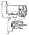
- an adjustable Pressure switch 13 connected at a minimum pressure from e.g. 1.5 to 2 bar switches on the pump so that the required pressure is built up.
- Turbine 14 driven.
- the rotation of the turbine is over a rotary signal transmitter, which consists of an on the axis of Turbine seated magnet 16 and a fixed one Magnetic field sensor 17 exists to control electronics 15 signals that the pump is kept on as long as the Turbine 14 acting as a flow sensor requires water extraction finds.
- the main advantage of the turbine is in that even with very little water withdrawal reacts and thus the operation of the pump in the desired Way is regulated.
- a minimum pressure switch 12 to the Main water pipe 11 are connected, which in If necessary, the pump switches off.
- Control electronics 15 be designed so that they are the pump switches off after a certain period of time during which the pressure set at the pressure switch 13 is undershot. This period of time can conveniently be about 5 seconds be.
- An upper pressure value need not be taken into account be, since the maximum pressure built up in the system to the corresponds to the nominal pressure of the pump.
Landscapes
- Engineering & Computer Science (AREA)
- Health & Medical Sciences (AREA)
- Life Sciences & Earth Sciences (AREA)
- Hydrology & Water Resources (AREA)
- Public Health (AREA)
- Water Supply & Treatment (AREA)
- Physics & Mathematics (AREA)
- General Physics & Mathematics (AREA)
- Fluid Mechanics (AREA)
- Automation & Control Theory (AREA)
- Control Of Non-Positive-Displacement Pumps (AREA)
- Measuring Volume Flow (AREA)
- Electrical Discharge Machining, Electrochemical Machining, And Combined Machining (AREA)
- Control Of Positive-Displacement Pumps (AREA)
- Control Of Fluid Pressure (AREA)
- Paper (AREA)
- Massaging Devices (AREA)
Description
Claims (4)
- Vorrichtung zur automatischen und konstanten Regelung des Wasserdruckes und des Wasserflusses in einer Wasserversorgungsanlage, bestehend aus einer in eine Hauptwasserleitung (11) schaltbaren Elektropumpe, einem an die Hauptwasserleitung (11) anschließbaren, einstellbaren Druckschalter (13), und einer Steuerelektronik (15), die geeignet ist, in Gebrauschsstellung bei Unterschreiten eines bestimmten wasserdruckes in der Hauptwasserleitung (11) die Pumpe einzuschalten
gekennzeichnet durch
eine in die Hauptwasserleitung (11) einbaubare Turbine (14) der Vorrichtung als Strömungssensor, der mit einem Drehsignalgeber (16, 17) der Vorrichtung zusammenwirkt, der an die Steuerelektronik (15) angeschlossen ist, um die Pumpe in Gebrauch nach dem Einschalten solange in Betrieb zu halten, solange der Strömungssensor einen Wasserfluß feststellt. - Vorrichtung nach Anspruch 1,
dadurch gekennzeichnet, daß
der Drehsignalgeber aus einem an der Turbine (14) angeordneten Magneten (16) und einem Magnetfeldsensor (17) besteht. - Vorrichtung nach Anspruch 1 oder 2,
gekennzeichnet durch
einen an die Hauptwasserleitung (11) anschließbaren Minimumdruckschalter (12) der Vorrichtung. - Vorrichtung nach einem der Ansprüche 1 oder 2,
dadurch gekennzeichnet, daß
die Steuerelektronik (15) geeignet ist die Pumpe bei Unterschreiten eines eingestellten Minimaldruckes nach einer bestimmten Zeitdauer abzuschalten.
Applications Claiming Priority (3)
| Application Number | Priority Date | Filing Date | Title |
|---|---|---|---|
| DE19503403 | 1995-02-02 | ||
| DE19503403A DE19503403A1 (de) | 1995-02-02 | 1995-02-02 | Regelvorrichtung für eine Wasserversorgungsanlage |
| PCT/EP1996/000429 WO1996023936A1 (de) | 1995-02-02 | 1996-02-01 | Regelvorrichtung für eine wasserversorgungsanlage |
Publications (2)
| Publication Number | Publication Date |
|---|---|
| EP0804654A1 EP0804654A1 (de) | 1997-11-05 |
| EP0804654B1 true EP0804654B1 (de) | 2002-09-18 |
Family
ID=7753010
Family Applications (1)
| Application Number | Title | Priority Date | Filing Date |
|---|---|---|---|
| EP96903962A Expired - Lifetime EP0804654B1 (de) | 1995-02-02 | 1996-02-01 | Regelvorrichtung für eine wasserversorgungsanlage |
Country Status (8)
| Country | Link |
|---|---|
| US (1) | US5738495A (de) |
| EP (1) | EP0804654B1 (de) |
| AT (1) | ATE224481T1 (de) |
| AU (1) | AU704151B2 (de) |
| CA (1) | CA2186996A1 (de) |
| DE (2) | DE19503403A1 (de) |
| ES (1) | ES2183931T3 (de) |
| WO (1) | WO1996023936A1 (de) |
Families Citing this family (17)
| Publication number | Priority date | Publication date | Assignee | Title |
|---|---|---|---|---|
| DE19611144C1 (de) * | 1996-03-21 | 1997-11-27 | Honeywell Ag | Wasserverteiler |
| IT1295577B1 (it) * | 1997-02-13 | 1999-05-13 | Hydroservice S R L | Dispositivo per il comando di una pompa idraulica,a controllo proporzionale computerizzato autoregolante |
| IT1309857B1 (it) * | 1999-08-06 | 2002-02-05 | Eng & Mark S R L | Macchina idraulica con integrato dispositivo automatico di controllo |
| DE10111739A1 (de) * | 2001-03-12 | 2002-10-02 | Gardena Kress & Kastner Gmbh | Pumpaggregat |
| US7901190B2 (en) * | 2004-07-28 | 2011-03-08 | Ian Gray | Pump control system |
| US20120039723A1 (en) * | 2009-02-13 | 2012-02-16 | Joel Dylan Gresham | Controller for a liquid supply pump |
| US8920131B2 (en) * | 2010-12-13 | 2014-12-30 | A.Y. Mcdonald Mfg. Co. | Pump control and method |
| ITFI20130231A1 (it) * | 2013-10-04 | 2015-04-05 | Trevi Engineering S R L Unipersona Le | "apparecchio per la gestione del flusso di un liquido" |
| CN103728990A (zh) * | 2013-11-25 | 2014-04-16 | 青岛盛嘉信息科技有限公司 | 一种水温自动调节方法 |
| US10385859B2 (en) | 2013-12-10 | 2019-08-20 | Franklin Electric Company, Inc. | In-line pressure boosting system and method |
| CN105484989A (zh) * | 2015-11-19 | 2016-04-13 | 宁波李立电器有限公司 | 一种改良的自动调压水泵 |
| CN105370556A (zh) * | 2015-11-19 | 2016-03-02 | 宁波李立电器有限公司 | 一种自动调压水泵 |
| CN105370555A (zh) * | 2015-11-19 | 2016-03-02 | 宁波李立电器有限公司 | 一种水泵调压装置 |
| JP6407223B2 (ja) * | 2016-09-27 | 2018-10-17 | 株式会社タブチ | メータユニット |
| US9857803B1 (en) | 2017-02-02 | 2018-01-02 | Water Dimmer, LLC | Water conservation system |
| CN107061300B (zh) * | 2017-04-25 | 2020-01-03 | 浙江新控泵业有限公司 | 智能低噪音自吸复合泵 |
| CN107514369A (zh) * | 2017-09-29 | 2017-12-26 | 浙江融乐环境科技有限公司 | 一种水泵与水泵出水阀门的联动装置 |
Family Cites Families (13)
| Publication number | Priority date | Publication date | Assignee | Title |
|---|---|---|---|---|
| DE805004C (de) * | 1948-12-06 | 1951-05-04 | Garvenswerke Maschinen Pumpen | Verfahren und Vorrichtung zur selbsttaetigen Schaltung von Hauswasserwerken kleiner Leistung |
| JPS5828436B2 (ja) * | 1973-11-30 | 1983-06-15 | 株式会社日立製作所 | ジドウシキポンプ |
| CA1058479A (en) * | 1975-05-19 | 1979-07-17 | Masaru Nishijyo | Automatically operative pumping equipment |
| JPS5814899B2 (ja) * | 1979-03-22 | 1983-03-23 | 株式会社日立製作所 | 自動給水装置 |
| DE3305316A1 (de) * | 1983-02-16 | 1984-08-23 | BHT Hygiene Technik GmbH, 8900 Augsburg | Spuelmaschine |
| DE3817018C2 (de) * | 1988-05-19 | 1997-07-17 | Iveco Magirus | Feuerlöschpumpen-Antriebsregelung |
| US4848097A (en) * | 1988-07-18 | 1989-07-18 | Roberts Mark J | Apparatus for transferring water from a container to a refrigerator ice maker |
| CA2101170A1 (en) * | 1991-01-22 | 1992-07-23 | Geoffrey R. Percival | Safety device |
| US5139044A (en) * | 1991-08-15 | 1992-08-18 | Otten Bernard J | Fluid control system |
| FR2690525B1 (fr) * | 1992-04-28 | 1997-03-21 | Sarrazin Jean Pierre | Procede et dispositif pour la detection de fuites d'eau dans des canalisations. |
| GB2283925B (en) * | 1993-10-11 | 1998-06-24 | Evans Gerald J | Meter and manifold assembly |
| US5464327A (en) * | 1993-12-01 | 1995-11-07 | Itt Corporation | Water pressure control system |
| US5580221A (en) * | 1994-10-05 | 1996-12-03 | Franklin Electric Co., Inc. | Motor drive circuit for pressure control of a pumping system |
-
1995
- 1995-02-02 DE DE19503403A patent/DE19503403A1/de not_active Withdrawn
-
1996
- 1996-02-01 AT AT96903962T patent/ATE224481T1/de not_active IP Right Cessation
- 1996-02-01 CA CA002186996A patent/CA2186996A1/en not_active Abandoned
- 1996-02-01 AU AU47861/96A patent/AU704151B2/en not_active Ceased
- 1996-02-01 EP EP96903962A patent/EP0804654B1/de not_active Expired - Lifetime
- 1996-02-01 ES ES96903962T patent/ES2183931T3/es not_active Expired - Lifetime
- 1996-02-01 DE DE59609691T patent/DE59609691D1/de not_active Expired - Fee Related
- 1996-02-01 WO PCT/EP1996/000429 patent/WO1996023936A1/de not_active Ceased
- 1996-11-18 US US08/722,100 patent/US5738495A/en not_active Expired - Fee Related
Also Published As
| Publication number | Publication date |
|---|---|
| WO1996023936A1 (de) | 1996-08-08 |
| AU4786196A (en) | 1996-08-21 |
| EP0804654A1 (de) | 1997-11-05 |
| US5738495A (en) | 1998-04-14 |
| CA2186996A1 (en) | 1996-08-08 |
| DE59609691D1 (de) | 2002-10-24 |
| ATE224481T1 (de) | 2002-10-15 |
| DE19503403A1 (de) | 1996-08-08 |
| AU704151B2 (en) | 1999-04-15 |
| ES2183931T3 (es) | 2003-04-01 |
Similar Documents
| Publication | Publication Date | Title |
|---|---|---|
| EP0804654B1 (de) | Regelvorrichtung für eine wasserversorgungsanlage | |
| EP0973082B1 (de) | Verfahren zur Regelung des Drucks eines Fluids | |
| EP0486819A1 (de) | Elektromotorisch betriebene Hydropumpe | |
| DE69004566T2 (de) | Vakuumpumpeneinheit. | |
| EP1464932B1 (de) | Druckregler und Vorrichtung zur kontinuierlichen Messung eines dynamischen Flüssigkeitsverbrauchs | |
| EP0970304A1 (de) | Vorrichtung und verfahren zum druckregeln in speichereinspritzsystemen mit einem elektromagnetisch betätigten druckstellglied | |
| EP0040595B1 (de) | Feuerlöschkreiselpumpe | |
| DE1961928B2 (de) | Vorrichtung zum Überwachen einer Rohrleitung auf Rohrbrüche | |
| DE69009272T2 (de) | Motorpumpengruppe mit Druck- und Förderstromsensoren. | |
| DE3811232C2 (de) | ||
| EP1731684B1 (de) | Betriebsverfahren für eine Abwasserhebeanlage und mit diesem Verfahren betriebenen Anlage | |
| DE3876396T2 (de) | Start- und anhaltekontrollvorrichtung einer hydraulischen pumpe. | |
| EP0444269A2 (de) | Verfahren zur Regelung der Leistung einer Pumpe | |
| DE3730940A1 (de) | Vorrichtung zur anzeige der stellung des kolbens eines ventils | |
| DE4316202C2 (de) | Verfahren zur Überwachung der Pumpgrenze eines Turboverdichters mit Vorleitapparat und Nachleitapparat | |
| EP0822332B1 (de) | Wasserkraftanlage | |
| EP0725995A1 (de) | Fernspeiseeinrichtung | |
| CH663824A5 (de) | Verfahren zur steuerung einer mehrstufigen, hydraulischen maschine. | |
| EP0264032A2 (de) | Verfahren zum Regeln von durchflussabhängigen Regelgrössen | |
| DE19510206B4 (de) | Regeleinrichtung für einen Hydraulikkreis | |
| DE69304798T2 (de) | Verfahren zum selektiven Schutz gegen Erdfehler in einem elektrischen Netz | |
| DE3117771C2 (de) | ||
| DE4303240C2 (de) | Verfahren zur Druckregelung in hydrostatischen Antriebssystemen | |
| DE3619147C2 (de) | Verfahren zur Kompensation von Verlusten einer verstellbaren Pumpe | |
| DE69005535T2 (de) | Undichter manometrischer Regler für hydraulische Kreise. |
Legal Events
| Date | Code | Title | Description |
|---|---|---|---|
| PUAI | Public reference made under article 153(3) epc to a published international application that has entered the european phase |
Free format text: ORIGINAL CODE: 0009012 |
|
| 17P | Request for examination filed |
Effective date: 19970102 |
|
| AK | Designated contracting states |
Kind code of ref document: A1 Designated state(s): AT BE CH DE DK ES FR GB GR IE IT LI NL PT SE |
|
| RAP1 | Party data changed (applicant data changed or rights of an application transferred) |
Owner name: LEADER PUMPS GROUP S.P.A. |
|
| RAP1 | Party data changed (applicant data changed or rights of an application transferred) |
Owner name: LEADER HOLDING S.R.L. |
|
| GRAG | Despatch of communication of intention to grant |
Free format text: ORIGINAL CODE: EPIDOS AGRA |
|
| 17Q | First examination report despatched |
Effective date: 20010928 |
|
| GRAG | Despatch of communication of intention to grant |
Free format text: ORIGINAL CODE: EPIDOS AGRA |
|
| GRAH | Despatch of communication of intention to grant a patent |
Free format text: ORIGINAL CODE: EPIDOS IGRA |
|
| GRAH | Despatch of communication of intention to grant a patent |
Free format text: ORIGINAL CODE: EPIDOS IGRA |
|
| GRAA | (expected) grant |
Free format text: ORIGINAL CODE: 0009210 |
|
| AK | Designated contracting states |
Kind code of ref document: B1 Designated state(s): AT BE CH DE DK ES FR GB GR IE IT LI NL PT SE |
|
| PG25 | Lapsed in a contracting state [announced via postgrant information from national office to epo] |
Ref country code: NL Free format text: LAPSE BECAUSE OF FAILURE TO SUBMIT A TRANSLATION OF THE DESCRIPTION OR TO PAY THE FEE WITHIN THE PRESCRIBED TIME-LIMIT Effective date: 20020918 Ref country code: IE Free format text: LAPSE BECAUSE OF FAILURE TO SUBMIT A TRANSLATION OF THE DESCRIPTION OR TO PAY THE FEE WITHIN THE PRESCRIBED TIME-LIMIT Effective date: 20020918 Ref country code: GR Free format text: LAPSE BECAUSE OF FAILURE TO SUBMIT A TRANSLATION OF THE DESCRIPTION OR TO PAY THE FEE WITHIN THE PRESCRIBED TIME-LIMIT Effective date: 20020918 Ref country code: GB Free format text: LAPSE BECAUSE OF FAILURE TO SUBMIT A TRANSLATION OF THE DESCRIPTION OR TO PAY THE FEE WITHIN THE PRESCRIBED TIME-LIMIT Effective date: 20020918 |
|
| REF | Corresponds to: |
Ref document number: 224481 Country of ref document: AT Date of ref document: 20021015 Kind code of ref document: T |
|
| REG | Reference to a national code |
Ref country code: GB Ref legal event code: FG4D Free format text: NOT ENGLISH |
|
| REG | Reference to a national code |
Ref country code: CH Ref legal event code: EP |
|
| REG | Reference to a national code |
Ref country code: IE Ref legal event code: FG4D Free format text: GERMAN |
|
| REF | Corresponds to: |
Ref document number: 59609691 Country of ref document: DE Date of ref document: 20021024 |
|
| RAP2 | Party data changed (patent owner data changed or rights of a patent transferred) |
Owner name: LEADER PUMPS GROUP S.P.A. |
|
| PG25 | Lapsed in a contracting state [announced via postgrant information from national office to epo] |
Ref country code: SE Free format text: LAPSE BECAUSE OF FAILURE TO SUBMIT A TRANSLATION OF THE DESCRIPTION OR TO PAY THE FEE WITHIN THE PRESCRIBED TIME-LIMIT Effective date: 20021218 Ref country code: DK Free format text: LAPSE BECAUSE OF FAILURE TO SUBMIT A TRANSLATION OF THE DESCRIPTION OR TO PAY THE FEE WITHIN THE PRESCRIBED TIME-LIMIT Effective date: 20021218 |
|
| PG25 | Lapsed in a contracting state [announced via postgrant information from national office to epo] |
Ref country code: PT Free format text: LAPSE BECAUSE OF FAILURE TO SUBMIT A TRANSLATION OF THE DESCRIPTION OR TO PAY THE FEE WITHIN THE PRESCRIBED TIME-LIMIT Effective date: 20021219 |
|
| NLT2 | Nl: modifications (of names), taken from the european patent patent bulletin |
Owner name: LEADER PUMPS GROUP S.P.A. |
|
| PG25 | Lapsed in a contracting state [announced via postgrant information from national office to epo] |
Ref country code: AT Free format text: LAPSE BECAUSE OF NON-PAYMENT OF DUE FEES Effective date: 20030201 |
|
| PGFP | Annual fee paid to national office [announced via postgrant information from national office to epo] |
Ref country code: FR Payment date: 20030218 Year of fee payment: 8 |
|
| PG25 | Lapsed in a contracting state [announced via postgrant information from national office to epo] |
Ref country code: LI Free format text: LAPSE BECAUSE OF NON-PAYMENT OF DUE FEES Effective date: 20030228 Ref country code: CH Free format text: LAPSE BECAUSE OF NON-PAYMENT OF DUE FEES Effective date: 20030228 Ref country code: BE Free format text: LAPSE BECAUSE OF NON-PAYMENT OF DUE FEES Effective date: 20030228 |
|
| NLV1 | Nl: lapsed or annulled due to failure to fulfill the requirements of art. 29p and 29m of the patents act | ||
| GBV | Gb: ep patent (uk) treated as always having been void in accordance with gb section 77(7)/1977 [no translation filed] |
Effective date: 20020918 |
|
| REG | Reference to a national code |
Ref country code: ES Ref legal event code: FG2A Ref document number: 2183931 Country of ref document: ES Kind code of ref document: T3 |
|
| ET | Fr: translation filed | ||
| PLBE | No opposition filed within time limit |
Free format text: ORIGINAL CODE: 0009261 |
|
| STAA | Information on the status of an ep patent application or granted ep patent |
Free format text: STATUS: NO OPPOSITION FILED WITHIN TIME LIMIT |
|
| REG | Reference to a national code |
Ref country code: IE Ref legal event code: FD4D Ref document number: 0804654E Country of ref document: IE |
|
| 26N | No opposition filed |
Effective date: 20030619 |
|
| REG | Reference to a national code |
Ref country code: CH Ref legal event code: PL |
|
| PG25 | Lapsed in a contracting state [announced via postgrant information from national office to epo] |
Ref country code: FR Free format text: LAPSE BECAUSE OF NON-PAYMENT OF DUE FEES Effective date: 20041029 |
|
| REG | Reference to a national code |
Ref country code: FR Ref legal event code: ST |
|
| PGFP | Annual fee paid to national office [announced via postgrant information from national office to epo] |
Ref country code: ES Payment date: 20080221 Year of fee payment: 13 |
|
| PGFP | Annual fee paid to national office [announced via postgrant information from national office to epo] |
Ref country code: IT Payment date: 20080228 Year of fee payment: 13 Ref country code: DE Payment date: 20080228 Year of fee payment: 13 |
|
| PG25 | Lapsed in a contracting state [announced via postgrant information from national office to epo] |
Ref country code: DE Free format text: LAPSE BECAUSE OF NON-PAYMENT OF DUE FEES Effective date: 20090901 |
|
| REG | Reference to a national code |
Ref country code: ES Ref legal event code: FD2A Effective date: 20090202 |
|
| PG25 | Lapsed in a contracting state [announced via postgrant information from national office to epo] |
Ref country code: ES Free format text: LAPSE BECAUSE OF NON-PAYMENT OF DUE FEES Effective date: 20090202 |
|
| PG25 | Lapsed in a contracting state [announced via postgrant information from national office to epo] |
Ref country code: IT Free format text: LAPSE BECAUSE OF NON-PAYMENT OF DUE FEES Effective date: 20090201 |