EP0804064B1 - Behältnis zum speichern, transportieren und ausbringen von flüssigkeit, insbesondere giesswasser oder trinkwasser - Google Patents
Behältnis zum speichern, transportieren und ausbringen von flüssigkeit, insbesondere giesswasser oder trinkwasser Download PDFInfo
- Publication number
- EP0804064B1 EP0804064B1 EP96900250A EP96900250A EP0804064B1 EP 0804064 B1 EP0804064 B1 EP 0804064B1 EP 96900250 A EP96900250 A EP 96900250A EP 96900250 A EP96900250 A EP 96900250A EP 0804064 B1 EP0804064 B1 EP 0804064B1
- Authority
- EP
- European Patent Office
- Prior art keywords
- container
- unit
- liquid pump
- hollow body
- solar cell
- Prior art date
- Legal status (The legal status is an assumption and is not a legal conclusion. Google has not performed a legal analysis and makes no representation as to the accuracy of the status listed.)
- Expired - Lifetime
Links
Images


Classifications
-
- B—PERFORMING OPERATIONS; TRANSPORTING
- B05—SPRAYING OR ATOMISING IN GENERAL; APPLYING FLUENT MATERIALS TO SURFACES, IN GENERAL
- B05B—SPRAYING APPARATUS; ATOMISING APPARATUS; NOZZLES
- B05B9/00—Spraying apparatus for discharge of liquids or other fluent material, without essentially mixing with gas or vapour
- B05B9/007—At least a part of the apparatus, e.g. a container, being provided with means, e.g. wheels, for allowing its displacement relative to the ground
-
- A—HUMAN NECESSITIES
- A01—AGRICULTURE; FORESTRY; ANIMAL HUSBANDRY; HUNTING; TRAPPING; FISHING
- A01G—HORTICULTURE; CULTIVATION OF VEGETABLES, FLOWERS, RICE, FRUIT, VINES, HOPS OR SEAWEED; FORESTRY; WATERING
- A01G25/00—Watering gardens, fields, sports grounds or the like
- A01G25/09—Watering arrangements making use of movable installations on wheels or the like
-
- A—HUMAN NECESSITIES
- A01—AGRICULTURE; FORESTRY; ANIMAL HUSBANDRY; HUNTING; TRAPPING; FISHING
- A01G—HORTICULTURE; CULTIVATION OF VEGETABLES, FLOWERS, RICE, FRUIT, VINES, HOPS OR SEAWEED; FORESTRY; WATERING
- A01G25/00—Watering gardens, fields, sports grounds or the like
- A01G25/14—Hand watering devices, e.g. watering cans
-
- A—HUMAN NECESSITIES
- A47—FURNITURE; DOMESTIC ARTICLES OR APPLIANCES; COFFEE MILLS; SPICE MILLS; SUCTION CLEANERS IN GENERAL
- A47K—SANITARY EQUIPMENT; ACCESSORIES THEREFOR, e.g. TOILET ACCESSORIES
- A47K3/00—Baths; Showers; Appurtenances therefor
- A47K3/28—Showers or bathing douches
- A47K3/283—Fixed showers
- A47K3/285—Free-standing or hanging showers without a cabinet
-
- B—PERFORMING OPERATIONS; TRANSPORTING
- B05—SPRAYING OR ATOMISING IN GENERAL; APPLYING FLUENT MATERIALS TO SURFACES, IN GENERAL
- B05B—SPRAYING APPARATUS; ATOMISING APPARATUS; NOZZLES
- B05B9/00—Spraying apparatus for discharge of liquids or other fluent material, without essentially mixing with gas or vapour
- B05B9/03—Spraying apparatus for discharge of liquids or other fluent material, without essentially mixing with gas or vapour characterised by means for supplying liquid or other fluent material
- B05B9/04—Spraying apparatus for discharge of liquids or other fluent material, without essentially mixing with gas or vapour characterised by means for supplying liquid or other fluent material with pressurised or compressible container; with pump
- B05B9/0403—Spraying apparatus for discharge of liquids or other fluent material, without essentially mixing with gas or vapour characterised by means for supplying liquid or other fluent material with pressurised or compressible container; with pump with pumps for liquids or other fluent material
-
- E—FIXED CONSTRUCTIONS
- E03—WATER SUPPLY; SEWERAGE
- E03B—INSTALLATIONS OR METHODS FOR OBTAINING, COLLECTING, OR DISTRIBUTING WATER
- E03B9/00—Methods or installations for drawing-off water
- E03B9/02—Hydrants; Arrangements of valves therein; Keys for hydrants
- E03B9/20—Pillar fountains or like apparatus for dispensing drinking water
-
- F—MECHANICAL ENGINEERING; LIGHTING; HEATING; WEAPONS; BLASTING
- F04—POSITIVE - DISPLACEMENT MACHINES FOR LIQUIDS; PUMPS FOR LIQUIDS OR ELASTIC FLUIDS
- F04B—POSITIVE-DISPLACEMENT MACHINES FOR LIQUIDS; PUMPS
- F04B17/00—Pumps characterised by combination with, or adaptation to, specific driving engines or motors
- F04B17/006—Solar operated
-
- Y—GENERAL TAGGING OF NEW TECHNOLOGICAL DEVELOPMENTS; GENERAL TAGGING OF CROSS-SECTIONAL TECHNOLOGIES SPANNING OVER SEVERAL SECTIONS OF THE IPC; TECHNICAL SUBJECTS COVERED BY FORMER USPC CROSS-REFERENCE ART COLLECTIONS [XRACs] AND DIGESTS
- Y02—TECHNOLOGIES OR APPLICATIONS FOR MITIGATION OR ADAPTATION AGAINST CLIMATE CHANGE
- Y02P—CLIMATE CHANGE MITIGATION TECHNOLOGIES IN THE PRODUCTION OR PROCESSING OF GOODS
- Y02P60/00—Technologies relating to agriculture, livestock or agroalimentary industries
- Y02P60/12—Technologies relating to agriculture, livestock or agroalimentary industries using renewable energies, e.g. solar water pumping
Definitions
- the present invention relates to a container for storage, Transporting and dispensing liquid, in particular Pouring water or drinking water, with a hollow body unit, vehicle rollers on the underside of the hollow body unit, an inlet opening, an outlet opening and a handle for rolling pulling the container.
- German utility model G 91 04 697.1 there is a watering can described, which is characterized in that casters are present, which are opposite in the can spout End region of the lower can side are arranged and the can spout extended as an operating lever is.
- This measure makes handling or transport the watering can improved.
- the problem remains that the watering can must be raised for watering, so that too increased effort is required here during the casting process itself is.
- the can spout is relatively long designed so that these can either be removed during casting must or is a hindrance to casting due to its length.
- the present invention has the technical problem or based on the task of a compared to the state of the art To specify technology-improved container of the type mentioned at the outset, which has a simple structure, a light one Transport ensured and pouring or taking water designed light and effective.
- the container according to the invention is characterized by the features of the independent Claim 1 given. Advantageous configurations and further developments are the subject of the dependent claims.
- the container according to the invention for storing, transporting and application of liquid is accordingly characterized from that on the outside of the container a solar cell device is arranged, a liquid pump device is available for pumping or sucking in the Inside the hollow body unit stored or to be stored Liquid and the solar cell device its generated electrical power at least partially to the liquid pump device delivers.
- a light plastic container is preferred for the container used, with a particular ease of movement the wheels must be observed. This allows the liquid (water) can be transported with little effort. At the same time will carry the heavy fluid load both bypassed during the transport process as well as during the casting process and the body becomes obsolete due to the loss of one-sided stress spared.
- a particularly preferred embodiment of the invention Container is characterized in that in the inlet area can be pulled out of the hollow body unit up to a stop flexible hose is available. This will make one allows easy filling.
- the flexible hose is made pulled out of the container and can easily be filled the water point or the tap are brought up.
- Another embodiment is a removable in the hose Strainer attached to keep floating materials away.
- the hollow body unit has a volume in the range from 20 to 40 l (liter), in particular approx. 35 l (liter).
- a particularly flexible embodiment of the invention Container is characterized in that the container has a Carrying handle and casting recesses arranged diametrically to the carrying handle, especially in the corner area of the handle are so that the container is like a watering can for watering can be used.
- solar cells are commercially available kind used that the necessary and sufficient Supply electricity for the built-in liquid pump device.
- the current is directly to the pump via built-in cables delivered.
- the pump can be used as a pressure pump or as a suction pump be trained.
- a pressure pump is used when the Liquid is used for pouring or removing.
- An additional suction pump is used if water from a sampling point must be sucked in.
- a particularly preferred embodiment of the invention Container is characterized in that the solar cell device their electrical power to a power storage unit emits to which the liquid pump device is connected is. This means that there is always an adequate one Amount of electrical energy available when needed for example by operating a simple switch device can be requested.
- the container according to the invention is provided with additional equipment still versatile in addition to the garden and cemetery area in the leisure area and to secure the drinking water supply applicable. So it is possible by means of an appropriate Holding device to connect a shower device or an aggregate for cooling the contents of the container To supply solar cell device with electricity, thus the possibility for drinking water supply, for example in the third world is possible. In addition, it can be done as already mentioned above the use of a solar powered suction pump be provided so that the container for example can be filled from troughs or watercourses.
- Devices for mixing can also be used in the hollow body unit of the container contents are provided by the Solar cell device can be powered, so too a container consisting of various components can be mixed homogeneously.
- a preferred embodiment of the container according to the invention is characterized in that the liquid pump device a first liquid pump unit for pumping and has a second liquid pump unit for suction, Another embodiment is characterized by that the first liquid pump unit in or on Housing and the second liquid pump unit in the area the free end of a flexible, with the inside of the housing communicating hose is arranged.
- the liquid pump units are each preferred as a centrifugal pump is formed. Arranging one at a time Centrifugal pump for pumping and a second centrifugal pump for suction brings a permanently reliable function in the With regard to the drive energy obtained from solar energy or the current intensity to be implemented thereby.
- the first centrifugal pump for emptying the container is located itself in the container and is placed so that the pump gyro emptied the container. In this process it will Water from the tank through the centrifugal pump into a drain hose pressed.
- the second centrifugal pump for filling of the container sits at the free end area of the flexible Drain hose and is installed so that by the Centrifugal pump sucked the water and into the container is pressed.
- Both pumps are designed so that the Drain the water through the suction pump without Resistance can flow through. In suction mode it will Water then also pumped through the pump without resistance pushed through and gets into the container. Through the Using two centrifugal pumps it is possible to use one Pump the liquid through the other without additional Pumping effort.
- a particularly preferred embodiment of the invention Container is characterized in that in the area of free end of a communicating with the inside of the housing Hose an inclination switch unit is present, the liquid pump device or the Liquid pump units depending on the inclination of the Tilt switch unit are switchable.
- the end region of the hose is preferred as a spray head trained in which the tilt switch unit is attached.
- the tilt switch unit is arranged so that the circuit for operating the first, for example Liquid pump unit only closes when the spray head from the vertical or from the horizontal Position is inclined downwards. Only then will the circuit closed and the pump can run. It becomes reliable prevents accidental start-up by a main switch on the housing to the start position the container is emptied without this being desired. Provided the spray head is properly attached to the container emptying not possible.
- the pumping pump is always switched on when the spray head is facing down.
- this is an advantageous operation of the container guaranteed as such since when spraying or Do not water this process with plants, for example the main switch on the housing must be interrupted, but discharging water from the tilt of the tilt switch unit is determined. Tilting it down will spread the water and point it upwards, d. H. beyond the horizontal, then through the tilt switch the circuit is interrupted and the pump stops.
- This is very advantageous and pleasant because it makes it easy Spraying or pouring can be interrupted. Also must one is not close to the container for pouring.
- a container 10 for storage is shown schematically in FIG. Transporting and dispensing liquid, in particular Irrigation water, shown.
- the container 10 has a hollow body unit 12, which in principle is cuboid and a cross-sectional area that tapers linearly upwards having.
- a handle 20 is formed, which is designed so that in A handle is created in the upper area, which is ergonomic the correct height for the average person.
- the container 10 is designed so that the Center of gravity of the filled container 10 relatively far below is easy to transport and good stability is possible.
- On the underside 44 of the container 10 are parallel spaced two vehicle roles in the side area 14 rotatably arranged about a common axis of rotation 42. These vehicle rollers 14 are used to transport the container 10.
- the vehicle rollers run smoothly and can in particular made of solid rubber in the running area.
- the container 10 is formed on the underside so that two are spaced apart arranged projection units 46 are present, so that the container 10 in the vertical shown in Figure 1 Form can be safely parked, in that it is one hand on the projection units 46 and the spaced support existing vehicle rollers 14 to the projection unit can.
- the protrusion units 46 and the vehicle rollers 14 are arranged so spaced that the filled container stands very stable.
- the projection units 46 are integrally formed on the underside 44 of the container 12.
- the container 10 is formed on a side wall 48 so that a handle 26 is formed.
- the container 10 with one hand of the operator from the vertical into the horizontal position and is therefore easy to carry.
- the handle is diametrically opposite Side at the top of the container 10, d. H. in the Corner area of the handle 20, a pouring opening with pouring recesses 28 attached so that the container 10 also manually how to empty a normal watering can.
- hose 30 mounted at one end with a funnel 32, a filter screen, not shown and provided with a stop 38 at its other end is.
- the hose can be used to fill the container 10 30 via a guide ring, not shown, from the container 10 are pulled out to the stop 38.
- the container 10 next to a water point 50 the is shown schematically in FIG. 1 as a tap, so that then with the hose 30 and the fixed Funnel 32 the container 10 can be filled with water can.
- the built-in sieve, not shown, is easily removable trained and can be cleaned of floating materials become.
- the one not required in the hollow body unit 12 Condition existing hose 30 allows that no outside extra storage holder for the hose attached must become.
- the hose is designed so that the hose 30 from the container 10 by bending the Stop can also be removed and renewed can.
- the container 10 itself is preferably a plastic container manufactured so that an inexpensive manufacturing process by spraying or blowing.
- the container volume is designed so that it is for the respective Use case makes sense.
- the volume can range from approx. 20 l (Liter) fluctuate up to 50 l (liter).
- a container with larger volumes can be constructed easily.
- chamfered upper region 53 of the container 10 is a solar cell device 22 attached on the outside.
- the solar cell device 22 consists of individual solar cell elements or solar film elements. The attachment is designed so that it is permanent.
- the solar cell device 22 is by a not shown in the drawing circumferential bead of the container 10 protected from bumps.
- the size of the solar cell device 22 and the power is dimensioned in such a way that sufficient current is used is available.
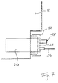
- the container 10 is prefabricated in the area of the outlet opening 18, that with a simple and waterproof union nut 52 the pressure pump 24 is inserted into the container 10 and can be screwed tight. By this measure is supported by additional sealing inserts permanent and reliable and leakproof attachment of the liquid pump possible, while at the same time easy disassembly is guaranteed for exchange purposes.
- the pump 24 is with power cables shown separately schematically in Figure 1 54 via a switching unit 56 to the solar cell device 22 connected.
- the power cables 54 are attached to the container 10 that the use is not affected.
- the pump 24 is from their output so dimensioned that on the one hand the solar cell device 22 provides the corresponding performance and on the other the water pressure is sufficient to empty the container 10 and to offer an optimal operating pressure.
- On the outside Part of the pump 24 has a flange 58 attached to it which is a flexible hose 34 that when emptying the guide the liquid to be emptied is attached can. The connection can be guaranteed by a push-on connection become.
- This correspondingly long flexible hose 34 is with a Nozzle 36 provided so that the liquid is convenient and light and especially also when keeping up at their place of use, like the garden, the grave or something else can be.
- the pump 24 is preferred by the switch unit 56 is designed as a toggle switch, and in the upper area of the Container 10 is placed in or put out of operation. This cable connection is also laid on the container 10, that safe use is given.
- the container 10 can so in terms of its own weight be constructed so that it can easily be used in the respective locations can be transported. Especially the handle, which allows the use as a "watering can” it, the container according to the invention easily for the purposes of his Transport to the respective site.
- the container 10 according to the invention can also in particular Leisure and camping area used as a water transporter become. This allows the water to be easily transported over long distances and well kept and easily removed become.
- the container 10 according to the invention is also for drinking water supply suitable for example in emergency areas, in a decentralized water supply should. There are particularly large refugee camps Water distribution problems due to large water collection vehicles usually only have a few delivery points.
- the container 10 according to the invention has a solar-powered one Cooling unit on that over the solar cell device 22 is supplied with power and installed on the container 10 is so that the food is cooled drinking water and is kept fresh.
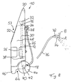
- the retrofit of the invention is for the leisure area Container 10 in a shower device 40 according to FIG. 5 possible, which is very easy to use.
- Preferred by one Conical bracket 62 becomes the shower device 40 by means of a locking screw 64 in the upper area attached to the side of the handle 20 and fixed in position.
- the locking screw 64 is inserted into the opening a stable rod 66 is introduced, the one in the upper area Has holder for receiving the hose 34.
- the shower device 40 By inserting the hose 34 into the holder 62 of the rod 66 creates a shower device 40, depending on the body size can be adjusted by the locking screw 64.
- the shower device 40 can be arranged at the end Nozzle 36 or operated with a normal caster, so that an individual setting is possible.
- the solar powered pump 24 secures the water supply and provides the necessary pressure for the shower process.
- the container is equipped with a suction pump. This is for example necessary in the scope if for example Garden owners do not have a tap available, but get their water from lakes, rivers or streams, for example.
- the container according to the invention is a very use-oriented one Construction that is inexpensive to manufacture and ensures permanent and reliable use. Solar energy is used to be inexpensive and environmentally friendly to provide a pouring container, that can be used in many ways.
- not shown of the container according to the invention are the vehicle roles of dimensioned in such a way that easily predetermined or predefinable step heights when transporting the container can be overcome.
- FIG. 8 There is a difference in the container 10 shown in FIG. 8 a flexible hose to the container according to FIG. 2 76 with a spray head 74 in the lower area of the container 10 connected.
- the same components have the same reference numerals like the components of FIG. 2 and will not be repeated explained.
- the liquid pump device as a two-part device formed with a first liquid pump unit 70, the lower area inside the container 10 is arranged and to which the flexible hose 76 is connected and with a second liquid pump unit 72 present in the area of the spray head 74 and is not shown in detail.
- the flexible hose 76 is on a holding unit 78 releasably attachable to the container 10, the Holding unit 78 is designed so that when attached Spray head 74 which is directed essentially upwards.
- the first Liquid pump unit 70 switches when the spray head 74 is held inclined downward (position A in Fig. 8th; shown in dashed lines). In this position of the spray head the first liquid pump unit 70 is supplied with current and pumps water out of the inside of the container. As soon as the spray head is taken up (position B in Fig. 8; shown in dashed lines), the power supply becomes first liquid pump unit 70 interrupted. Thereby a pleasant pouring process can be accomplished without that awkward to pour or to turn off the water Switching units located on the container are actuated Need to become. In addition, the operating position when casting depending on the length of the flexible Hose 76 be away from the container.
- the container can either be filled using a suction pump or through the funnel through a tap.
- a level indicator unit through which the filling can be observed and which the shows the respective filling quantity.
- the solar unit removably attached to the housing.
- the standard type is powered by accumulators, which are preferred are rechargeable.
- the solar unit is available as an additional module, for example in a prefabricated one Recesses on the housing is clipped and in addition connected to the battery.
Landscapes
- Engineering & Computer Science (AREA)
- Life Sciences & Earth Sciences (AREA)
- Public Health (AREA)
- Water Supply & Treatment (AREA)
- Health & Medical Sciences (AREA)
- Environmental Sciences (AREA)
- Hydrology & Water Resources (AREA)
- General Health & Medical Sciences (AREA)
- Epidemiology (AREA)
- Sustainable Development (AREA)
- Sustainable Energy (AREA)
- Mechanical Engineering (AREA)
- General Engineering & Computer Science (AREA)
- Bathtubs, Showers, And Their Attachments (AREA)
- Details Of Rigid Or Semi-Rigid Containers (AREA)
- Devices For Dispensing Beverages (AREA)
- Reciprocating Pumps (AREA)
Abstract
Description
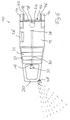
- Fig. 1
- schematische Seitenansicht eines Behältnisses mit flexiblem Einfüllschlauch und flexiblem Auslaßschlauch mit einer Druckpumpe,
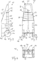
- Fig. 2
- Seitenansicht des Behältnis gemäß Figur 1 ohne die flexiblen Schläuche,
- Fig. 3
- Vorderansicht des Behältnis gemäß Figur 2,
- Fig. 4
- Draufsicht auf das Behältnis gemäß Figur 2,
- Fig. 5
- schematische Ansicht eines Behältnis mit angeschlossener Duschvorrichtung,
- Fig. 6
- schematische Ansicht des Einsatzes eines Behältnis gemäß Figur 2 als Gießkanne,
- Fig. 7
- schematische Detailansicht im Anschlußbereich der Druckpumpe und
- Fig. 8
- schematische Seitenansicht eines Behältnis mit zwei Flüssigkeitspumpeneinheiten.
Claims (18)
- Behältnis (10) zum Speichern, Transportieren und Ausbringen von Flüssigkeit, insbesondere Gießwasser oder Trinkwasser, miteiner Hohlkörpereinheit (12),unterseitig an der Hohlkörpereinheit vorhandenen Fahrzeugrollen (14),einer Einlaßöffnung (16),einer Auslaßöffnung (18) undeiner Handhabe zum rollenden Ziehen des Behältnis (10)
dadurch gekennzeichnet, daßaußenseitig an dem Behältnis eine Solarzelleneinrichtung (22) angeordnet ist,eine Flüssigkeitspumpeneinrichtung (24) vorhanden ist zum bedarfsweise Abpumpen oder Ansaugen der im Inneren der Hohlkörpereinheit (12) gespeicherten bzw. zu speichernden Flüssigkeit unddie Solarzelleneinrichtung (22) ihre erzeugte elektrische Leistung zumindest teilweise an die Flüssigkeitspumpeneinrichtung (24) abgibt. - Behältnis nach Anspruch 1,
dadurch gekennzeichnet, daß
die Solarzelleneinrichtung ihre elektrische Leistung an eine Stromspeichereinheit abgibt, an die die Flüssigkeitspumpeneinrichtung angeschlossen ist. - Behältnis nach Anspruch 1 und/oder 2,
dadurch gekennzeichnet, daß
das Behältnis (10) einen Tragegriff (26) und diametral zu dem Tragegriff (26) angeordnete Gießausnehmungen (28), insbesondere im Eckbereich der Handhabe (20), vorhanden sind, so daß das Behältnis (10) wie eine Gießkanne zum Gießen benutzt werden kann. - Behältnis nach einem oder mehreren der vorstehenden Ansprüche,
dadurch gekennzeichnet, daß
im Einlaßbereich (16) ein bis zu einem Anschlag aus der Hohlkörpereinheit (12) herausziehbarer flexibler Schlauch (30) vorhanden ist. - Behältnis in Anspruch 4,
dadurch gekennzeichnet, daß
das Einfüllende des Schlauches (30) trichterförmig ausgebildet ist. - Behältnis nach einem oder mehreren der vorstehenden Ansprüche,
dadurch gekennzeichnet, daß
ein Kälteaggregat vorhanden ist, an das die Solarzelleneinheit zumindest teilweise im Bedarfsfall ihre elektrische Energie abgibt. - Behältnis nach einem oder mehreren der vorstehenden Ansprüche,
dadurch gekennzeichnet, daß
das Behältnis und/oder die Fahrzeugrollen aus Kunststoff bestehen. - Behältnis nach einem oder mehreren der vorstehenden Ansprüche,
dadurch gekennzeichnet, daß
an der Auslaßöffnung (18) eine Schlauchanschlußeinheit insbesondere zum Anschließen eines flexiblen Schlauches (34) angeordnet ist. - Behältnis nach einem oder mehreren der vorstehenden Ansprüche,
dadurch gekennzeichnet, daß
die als Griffeinheit ausgebildete Handhabe in einer Höhe vorhanden ist, in der sie von der Bedienperson problemlos ergriffen werden kann. - Behältnis nach einem oder mehreren der vorstehenden Ansprüche,
dadurch gekennzeichnet, daß
die Hohlkörpereinheit im wesentlichen eine Quaderform aufweist. - Behältnis nach einem oder mehreren der vorstehenden Ansprüche,
dadurch gekennzeichnet, daß
das Volumen der Hohlkörpereinheit (12) 20 bis 50 l (Liter), insbesondere ca. 35 l (Liter), beträgt. - Behältnis nach einem oder mehreren der vorstehenden Ansprüche,
dadurch gekennzeichnet, daß
das Behältnis eine Stromanschlußeinheit aufweist, die von der Solarzelleneinrichtung mit Strom beaufschlagt wird und an die externe Stromverbrauchseinheiten angeschlossen werden können. - Behältnis nach einem oder mehreren der vorstehenden Ansprüche,
gekennzeichnet durch
eine am Behältnis lösbar befestigbare Duscheinheit. - Behältnis nach einem oder mehreren der vorstehenden Ansprüche,
dadurch gekennzeichnet, daß
die Flüssigkeitspumpeneinrichtung eine erste Flüssigkeitspumpeneinheit (70) zum Abpumpen und eine zweite Flüssigkeitspumpeneinheit (72) zum Ansaugen aufweist. - Behältnis nach Anspruch 14,
dadurch gekennzeichnet, daß
die erste Flüssigkeitspumpeneinheit (70) in oder am Gehäuse und die zweite Flüssigkeitspumpeneinheit (72) im Bereich des freien Endes eines flexiblen, mit dem Inneren des Gehäuses kommunizierenden Schlauches (76) angeordnet ist. - Behältnis nach Anspruch 14 und/oder 15,
dadurch gekennzeichnet, daß
die Flüssigkeitspumpeneinheiten jeweils als Kreiselpumpenaggregate ausgebildet sind. - Behältnis nach einem oder mehreren der vorstehenden Ansprüche,
dadurch gekennzeichnet, daß
im Bereich des freien Endes eines mit dem Inneren des Gehäuses kommunizierenden Schlauches eine Neigungsschalteinheit vorhanden ist, wobei die Flüssigkeitspumpeneinrichtung beziehungsweise die Flüssigkeitspumpeneinheiten in Abhängigkeit der Neigung der Neigungsschalteinheit schaltbar ist beziehungsweise sind. - Behältnis nach dem Oberbegriff von Anspruch 1,
dadurch gekennzeichnet, daßeine Akkumulatoreneinheit vorhanden ist,eine Flüssigkeitspumpeneinrichtung (24) vorhanden ist zum bedarfsweise Abpumpen oder Ansaugen der im Inneren der Hohlkörpereinheit (12) gespeicherten bzw. zu speichernden Flüssigkeit unddie Akkumulatoreneinheit ihre erzeugte elektrische Leistung zumindest teilweise an die Flüssigkeitspumpeneinrichtung (24) abgibt,an der Hohlkörpereinheit eine Lagereinheit zum lösbaren Befestigen einer Solarzelleneinrichtung vorhanden ist.
Applications Claiming Priority (5)
| Application Number | Priority Date | Filing Date | Title |
|---|---|---|---|
| DE29500710U | 1995-01-18 | ||
| DE29500710U DE29500710U1 (de) | 1995-01-18 | 1995-01-18 | Behältnis zum Speichern, Transportieren und Ausbringen von Flüssigkeit, insbesondere Gießwasser oder Trinkwasser |
| DE29511629U | 1995-07-19 | ||
| DE29511629U DE29511629U1 (de) | 1995-01-18 | 1995-07-19 | Behältnis zum Speichern, Transportieren und Ausbringen von Flüssigkeiten, insbesondere Gießwasser oder Trinkwasser |
| PCT/DE1996/000009 WO1996022013A1 (de) | 1995-01-18 | 1996-01-05 | Behältnis zum speichern, transportieren und ausbringen von flüssigkeit, insbesondere giesswasser oder trinkwasser |
Publications (2)
| Publication Number | Publication Date |
|---|---|
| EP0804064A1 EP0804064A1 (de) | 1997-11-05 |
| EP0804064B1 true EP0804064B1 (de) | 1999-03-24 |
Family
ID=26057502
Family Applications (1)
| Application Number | Title | Priority Date | Filing Date |
|---|---|---|---|
| EP96900250A Expired - Lifetime EP0804064B1 (de) | 1995-01-18 | 1996-01-05 | Behältnis zum speichern, transportieren und ausbringen von flüssigkeit, insbesondere giesswasser oder trinkwasser |
Country Status (5)
| Country | Link |
|---|---|
| US (1) | US5961048A (de) |
| EP (1) | EP0804064B1 (de) |
| AU (1) | AU4384496A (de) |
| ES (1) | ES2132869T3 (de) |
| WO (1) | WO1996022013A1 (de) |
Families Citing this family (26)
| Publication number | Priority date | Publication date | Assignee | Title |
|---|---|---|---|---|
| IT1288061B1 (it) * | 1996-12-17 | 1998-09-10 | Lorenzo Schia | Dispositivo per la nebulizzazione di sostanze liquide |
| IT1297575B1 (it) * | 1997-12-11 | 1999-12-17 | Calipso Srl | Sistema di alimentazione elettrica per box doccia o colonna attrezzata multifunzione |
| ITPA980005A1 (it) * | 1998-02-26 | 1999-08-26 | Giuseppe Fuca | Contenitore su ruote per l'irrigazione automatica dei vasi da giardino e da appartamento. |
| US6047898A (en) * | 1998-05-29 | 2000-04-11 | Alert Services, Inc. | Portable fountain |
| DE29916317U1 (de) * | 1999-09-16 | 1999-12-30 | Koch, Ludwig, 64319 Pfungstadt | Verfahrbare Speichervorrichtung |
| DE10106463A1 (de) * | 2001-02-13 | 2002-08-14 | Hirschmann Laborgeraete Gmbh | Digitalbürette und Verfahren zum Anzeigen des Dosiervolumens einer solchen Digitalbürette |
| DE10123096C1 (de) * | 2001-05-08 | 2002-09-19 | Michael Schwenke | Gießrohr |
| US6981613B1 (en) * | 2002-12-06 | 2006-01-03 | Cullen Kamisugi | Portable pressurized liquid storage system |
| GB0317019D0 (en) * | 2003-07-23 | 2003-08-27 | Hancock John | A roller |
| US7418832B2 (en) * | 2003-10-21 | 2008-09-02 | William R Ferrono | Portable mister for adjusting ambient temperature |
| WO2006029477A1 (en) * | 2004-09-17 | 2006-03-23 | George Bito | Portable liquid dispensing apparatus |
| KR100678841B1 (ko) | 2005-05-21 | 2007-02-05 | 이홍복 | 이동식 스프링클러 |
| US7464735B2 (en) * | 2005-06-08 | 2008-12-16 | Kelcamax Innovations, Llc | Funnel stand with retractable hose |
| US20080203117A1 (en) * | 2007-02-26 | 2008-08-28 | Townsend Robert L | Fresh water tote a long |
| AT504339B8 (de) * | 2007-03-15 | 2008-09-15 | Schmidt Franz | Giesskanne |
| US7789329B2 (en) * | 2008-04-29 | 2010-09-07 | Chapin Manufacturing, Inc. | Filtering apparatus for inlet fluid into a pressure chamber of a sprayer |
| US8714411B2 (en) | 2010-12-02 | 2014-05-06 | Back Road Ventures, Inc. | Portable fluid treatment and dispensing system |
| ITMO20120268A1 (it) * | 2012-10-31 | 2014-05-01 | Fabrizio Comastri | Sistema di irrigazione. |
| CN102941174A (zh) * | 2012-11-17 | 2013-02-27 | 陈海 | 电动喷雾器 |
| US9415410B2 (en) | 2013-03-15 | 2016-08-16 | Chapin Manufacturing, Inc. | Clog retarding filtering apparatus for inlet fluid into a pressure chamber of a sprayer |
| DE102013009795A1 (de) * | 2013-06-12 | 2014-12-18 | Stephan Krüger | Vorrichtung zum Befüllen von Gießkannen |
| CN105660318A (zh) * | 2016-04-08 | 2016-06-15 | 赵静 | 一种双管式喷水器 |
| CN106037562A (zh) * | 2016-07-14 | 2016-10-26 | 殷永生 | 简易淋浴装置 |
| CN106376434A (zh) * | 2016-08-29 | 2017-02-08 | 山东胜伟园林科技有限公司 | 一种基于物联网的视频扫描喷灌系统 |
| US11529024B2 (en) * | 2020-01-31 | 2022-12-20 | Outdoor Culture Inc. | Portable solar shower with vacuum insulated water tank |
| US12214368B1 (en) * | 2021-04-28 | 2025-02-04 | EZ Hose LLC | Hose motion sensor valve system |
Family Cites Families (19)
| Publication number | Priority date | Publication date | Assignee | Title |
|---|---|---|---|---|
| FR1453606A (fr) * | 1965-11-09 | 1966-09-23 | Appareil à douche portatif à usage individuel | |
| CH557203A (de) * | 1972-08-31 | 1974-12-31 | Graef Helmut | Gartenspritzgeraet. |
| DE2404341A1 (de) * | 1974-01-30 | 1975-07-31 | Fischer & Co Industrieberatung | Behaelter sowie zubehoer- und werkzeughalterungen zum tragen und mittels untersatz fahrbar |
| US3940065A (en) * | 1975-03-14 | 1976-02-24 | Graco Inc. | Portable spraying apparatus |
| US3939503A (en) * | 1975-04-16 | 1976-02-24 | Nazworth Harold W | Portable emergency safety shower |
| US4269329A (en) * | 1978-05-19 | 1981-05-26 | Keller Terry M | Plant-watering device |
| DE2851793A1 (de) * | 1978-11-30 | 1980-06-12 | Ulrich Dipl Ing Luboschik | Solarer dusch- und warmwasserkollektor |
| US4567563A (en) * | 1980-12-30 | 1986-01-28 | Energy Management Corporation | Irrigation control system |
| US4700892A (en) * | 1986-10-10 | 1987-10-20 | Blue Mountain Products, Inc. | Misting and watering can |
| US4945672A (en) * | 1988-11-02 | 1990-08-07 | Raia John A | Water circulating and aerating device for live bait containers |
| DE8901123U1 (de) * | 1989-01-30 | 1989-03-23 | Gerdes GmbH, 5014 Kerpen | Tragbarer Wasserspender |
| US5104016A (en) * | 1990-02-12 | 1992-04-14 | Bikestream, Inc. | Pressurized potable beverage drinking system |
| US5111538A (en) * | 1990-06-04 | 1992-05-12 | Chapman Donald L | Knockdown portable hotwater shower and shower head therefor |
| US5040726A (en) * | 1990-06-25 | 1991-08-20 | Dimitri Amir T | Solar energy powered water fountain |
| US5154317A (en) * | 1990-07-09 | 1992-10-13 | Roppolo Iii Michael A | Portable liquid dispenser |
| DE9104697U1 (de) * | 1991-04-17 | 1991-07-18 | Ellwart, Heinrich | Gießkanne |
| US5506565A (en) * | 1993-06-25 | 1996-04-09 | Andrew De Leon; Joseph | Device for signaling the felling of a tree and a system for forest conservation |
| US5484538A (en) * | 1993-09-14 | 1996-01-16 | Texavia International, Inc. | Multiple service water purifier and dispenser and process of purifying water |
| DE29500710U1 (de) * | 1995-01-18 | 1995-03-30 | Prieschl, Herbert, 74626 Bretzfeld | Behältnis zum Speichern, Transportieren und Ausbringen von Flüssigkeit, insbesondere Gießwasser oder Trinkwasser |
-
1996
- 1996-01-05 EP EP96900250A patent/EP0804064B1/de not_active Expired - Lifetime
- 1996-01-05 AU AU43844/96A patent/AU4384496A/en not_active Abandoned
- 1996-01-05 ES ES96900250T patent/ES2132869T3/es not_active Expired - Lifetime
- 1996-01-05 WO PCT/DE1996/000009 patent/WO1996022013A1/de not_active Ceased
- 1996-01-05 US US08/875,801 patent/US5961048A/en not_active Expired - Fee Related
Also Published As
| Publication number | Publication date |
|---|---|
| US5961048A (en) | 1999-10-05 |
| ES2132869T3 (es) | 1999-08-16 |
| EP0804064A1 (de) | 1997-11-05 |
| WO1996022013A1 (de) | 1996-07-25 |
| AU4384496A (en) | 1996-08-07 |
Similar Documents
| Publication | Publication Date | Title |
|---|---|---|
| EP0804064B1 (de) | Behältnis zum speichern, transportieren und ausbringen von flüssigkeit, insbesondere giesswasser oder trinkwasser | |
| DE69426661T2 (de) | Raumsparende Vakuumtoilettenanordnung | |
| DE4231826A1 (de) | Einrichtung zur Feinzerstäubung von Flüssigkeiten | |
| DE102018006973B3 (de) | Vorrichtung zur Ver- und/oder Entsorgung von Flüssigkeiten in Wohnwagen und/oder Wohnmobilen | |
| DE29908357U1 (de) | Oberflächenpumpe, insbesondere Gartenpumpe | |
| DE29511629U1 (de) | Behältnis zum Speichern, Transportieren und Ausbringen von Flüssigkeiten, insbesondere Gießwasser oder Trinkwasser | |
| DE9403745U1 (de) | Hochdruckreiniger | |
| DE29802380U1 (de) | Transportables Heizgerät | |
| DE202009010329U1 (de) | Mobile Reinigungsvorrichtung | |
| DE20115721U1 (de) | Zusammenfaltbare Duschzelle | |
| DE8811746U1 (de) | Krankenwaschvorrichtung | |
| DE202018003530U1 (de) | Anordnung zur Aufnahme einer Reinigungsflüssigkeit | |
| EP0804897A2 (de) | Bodenreinigungsmaschine, insbesondere Scheuersaugmaschine | |
| DE60110280T2 (de) | Konstruktion eines Vakuumbehälters | |
| DE69721722T2 (de) | Kombinierter Vakuum- und Lagerbehälter | |
| DE29719205U1 (de) | Mobile Flüssigkeitsversorgungsanlage | |
| DE3529604C2 (de) | Vorrichtung zum Befeuchten und/oder Reinigen von Luft | |
| EP2071940B1 (de) | Vorrichtung zum Transportieren und Ausbringen von Fluessigkeit | |
| DE102025126613A1 (de) | Reinigungsgerät | |
| DE102025126617A1 (de) | Saugdüse, Handstück und Reinigungsgerät | |
| WO2026082957A1 (de) | Reinigungsgerät | |
| EP4619172A1 (de) | Druckreinigungssystem | |
| DE69215087T2 (de) | Transportable Flüssigkeitabgabevorrichtung | |
| DE102025126616A1 (de) | Reinigungsgerät und Verfahren zum Reinigen einer Oberfläche mit einem Reinigungsgerät | |
| EP1069057A1 (de) | Behälter zur Aufnahme kompostierbarer Materialien |
Legal Events
| Date | Code | Title | Description |
|---|---|---|---|
| PUAI | Public reference made under article 153(3) epc to a published international application that has entered the european phase |
Free format text: ORIGINAL CODE: 0009012 |
|
| 17P | Request for examination filed |
Effective date: 19970724 |
|
| AK | Designated contracting states |
Kind code of ref document: A1 Designated state(s): DE ES FR GB IT |
|
| GRAG | Despatch of communication of intention to grant |
Free format text: ORIGINAL CODE: EPIDOS AGRA |
|
| 17Q | First examination report despatched |
Effective date: 19980209 |
|
| GRAG | Despatch of communication of intention to grant |
Free format text: ORIGINAL CODE: EPIDOS AGRA |
|
| GRAH | Despatch of communication of intention to grant a patent |
Free format text: ORIGINAL CODE: EPIDOS IGRA |
|
| GRAH | Despatch of communication of intention to grant a patent |
Free format text: ORIGINAL CODE: EPIDOS IGRA |
|
| GRAH | Despatch of communication of intention to grant a patent |
Free format text: ORIGINAL CODE: EPIDOS IGRA |
|
| GRAA | (expected) grant |
Free format text: ORIGINAL CODE: 0009210 |
|
| AK | Designated contracting states |
Kind code of ref document: B1 Designated state(s): DE ES FR GB IT |
|
| REF | Corresponds to: |
Ref document number: 59601500 Country of ref document: DE Date of ref document: 19990429 |
|
| ITF | It: translation for a ep patent filed | ||
| GBT | Gb: translation of ep patent filed (gb section 77(6)(a)/1977) |
Effective date: 19990429 |
|
| ET | Fr: translation filed | ||
| REG | Reference to a national code |
Ref country code: ES Ref legal event code: FG2A Ref document number: 2132869 Country of ref document: ES Kind code of ref document: T3 |
|
| PLBE | No opposition filed within time limit |
Free format text: ORIGINAL CODE: 0009261 |
|
| STAA | Information on the status of an ep patent application or granted ep patent |
Free format text: STATUS: NO OPPOSITION FILED WITHIN TIME LIMIT |
|
| 26N | No opposition filed | ||
| REG | Reference to a national code |
Ref country code: GB Ref legal event code: IF02 |
|
| PGFP | Annual fee paid to national office [announced via postgrant information from national office to epo] |
Ref country code: GB Payment date: 20021212 Year of fee payment: 8 |
|
| PGFP | Annual fee paid to national office [announced via postgrant information from national office to epo] |
Ref country code: FR Payment date: 20030120 Year of fee payment: 8 |
|
| PGFP | Annual fee paid to national office [announced via postgrant information from national office to epo] |
Ref country code: ES Payment date: 20030130 Year of fee payment: 8 |
|
| PG25 | Lapsed in a contracting state [announced via postgrant information from national office to epo] |
Ref country code: GB Free format text: LAPSE BECAUSE OF NON-PAYMENT OF DUE FEES Effective date: 20040105 |
|
| PG25 | Lapsed in a contracting state [announced via postgrant information from national office to epo] |
Ref country code: ES Free format text: LAPSE BECAUSE OF NON-PAYMENT OF DUE FEES Effective date: 20040107 |
|
| PGFP | Annual fee paid to national office [announced via postgrant information from national office to epo] |
Ref country code: DE Payment date: 20040119 Year of fee payment: 9 |
|
| GBPC | Gb: european patent ceased through non-payment of renewal fee |
Effective date: 20040105 |
|
| PG25 | Lapsed in a contracting state [announced via postgrant information from national office to epo] |
Ref country code: FR Free format text: LAPSE BECAUSE OF NON-PAYMENT OF DUE FEES Effective date: 20040930 |
|
| REG | Reference to a national code |
Ref country code: FR Ref legal event code: ST |
|
| PG25 | Lapsed in a contracting state [announced via postgrant information from national office to epo] |
Ref country code: IT Free format text: LAPSE BECAUSE OF NON-PAYMENT OF DUE FEES Effective date: 20050105 |
|
| REG | Reference to a national code |
Ref country code: ES Ref legal event code: FD2A Effective date: 20040107 |
|
| PG25 | Lapsed in a contracting state [announced via postgrant information from national office to epo] |
Ref country code: DE Free format text: LAPSE BECAUSE OF NON-PAYMENT OF DUE FEES Effective date: 20050802 |