EP0804064B1 - Container for storing, transporting and dispensing liquid, especially water for drinking or watering - Google Patents
Container for storing, transporting and dispensing liquid, especially water for drinking or watering Download PDFInfo
- Publication number
- EP0804064B1 EP0804064B1 EP96900250A EP96900250A EP0804064B1 EP 0804064 B1 EP0804064 B1 EP 0804064B1 EP 96900250 A EP96900250 A EP 96900250A EP 96900250 A EP96900250 A EP 96900250A EP 0804064 B1 EP0804064 B1 EP 0804064B1
- Authority
- EP
- European Patent Office
- Prior art keywords
- container
- unit
- liquid pump
- hollow body
- solar cell
- Prior art date
- Legal status (The legal status is an assumption and is not a legal conclusion. Google has not performed a legal analysis and makes no representation as to the accuracy of the status listed.)
- Expired - Lifetime
Links
Images


Classifications
-
- B—PERFORMING OPERATIONS; TRANSPORTING
- B05—SPRAYING OR ATOMISING IN GENERAL; APPLYING FLUENT MATERIALS TO SURFACES, IN GENERAL
- B05B—SPRAYING APPARATUS; ATOMISING APPARATUS; NOZZLES
- B05B9/00—Spraying apparatus for discharge of liquids or other fluent material, without essentially mixing with gas or vapour
- B05B9/007—At least a part of the apparatus, e.g. a container, being provided with means, e.g. wheels, for allowing its displacement relative to the ground
-
- A—HUMAN NECESSITIES
- A01—AGRICULTURE; FORESTRY; ANIMAL HUSBANDRY; HUNTING; TRAPPING; FISHING
- A01G—HORTICULTURE; CULTIVATION OF VEGETABLES, FLOWERS, RICE, FRUIT, VINES, HOPS OR SEAWEED; FORESTRY; WATERING
- A01G25/00—Watering gardens, fields, sports grounds or the like
- A01G25/09—Watering arrangements making use of movable installations on wheels or the like
-
- A—HUMAN NECESSITIES
- A01—AGRICULTURE; FORESTRY; ANIMAL HUSBANDRY; HUNTING; TRAPPING; FISHING
- A01G—HORTICULTURE; CULTIVATION OF VEGETABLES, FLOWERS, RICE, FRUIT, VINES, HOPS OR SEAWEED; FORESTRY; WATERING
- A01G25/00—Watering gardens, fields, sports grounds or the like
- A01G25/14—Hand watering devices, e.g. watering cans
-
- A—HUMAN NECESSITIES
- A47—FURNITURE; DOMESTIC ARTICLES OR APPLIANCES; COFFEE MILLS; SPICE MILLS; SUCTION CLEANERS IN GENERAL
- A47K—SANITARY EQUIPMENT NOT OTHERWISE PROVIDED FOR; TOILET ACCESSORIES
- A47K3/00—Baths; Douches; Appurtenances therefor
- A47K3/28—Showers or bathing douches
- A47K3/283—Fixed showers
- A47K3/285—Free-standing or hanging showers without a cabinet
-
- B—PERFORMING OPERATIONS; TRANSPORTING
- B05—SPRAYING OR ATOMISING IN GENERAL; APPLYING FLUENT MATERIALS TO SURFACES, IN GENERAL
- B05B—SPRAYING APPARATUS; ATOMISING APPARATUS; NOZZLES
- B05B9/00—Spraying apparatus for discharge of liquids or other fluent material, without essentially mixing with gas or vapour
- B05B9/03—Spraying apparatus for discharge of liquids or other fluent material, without essentially mixing with gas or vapour characterised by means for supplying liquid or other fluent material
- B05B9/04—Spraying apparatus for discharge of liquids or other fluent material, without essentially mixing with gas or vapour characterised by means for supplying liquid or other fluent material with pressurised or compressible container; with pump
- B05B9/0403—Spraying apparatus for discharge of liquids or other fluent material, without essentially mixing with gas or vapour characterised by means for supplying liquid or other fluent material with pressurised or compressible container; with pump with pumps for liquids or other fluent material
-
- E—FIXED CONSTRUCTIONS
- E03—WATER SUPPLY; SEWERAGE
- E03B—INSTALLATIONS OR METHODS FOR OBTAINING, COLLECTING, OR DISTRIBUTING WATER
- E03B9/00—Methods or installations for drawing-off water
- E03B9/02—Hydrants; Arrangements of valves therein; Keys for hydrants
- E03B9/20—Pillar fountains or like apparatus for dispensing drinking water
-
- F—MECHANICAL ENGINEERING; LIGHTING; HEATING; WEAPONS; BLASTING
- F04—POSITIVE - DISPLACEMENT MACHINES FOR LIQUIDS; PUMPS FOR LIQUIDS OR ELASTIC FLUIDS
- F04B—POSITIVE-DISPLACEMENT MACHINES FOR LIQUIDS; PUMPS
- F04B17/00—Pumps characterised by combination with, or adaptation to, specific driving engines or motors
- F04B17/006—Solar operated
-
- Y—GENERAL TAGGING OF NEW TECHNOLOGICAL DEVELOPMENTS; GENERAL TAGGING OF CROSS-SECTIONAL TECHNOLOGIES SPANNING OVER SEVERAL SECTIONS OF THE IPC; TECHNICAL SUBJECTS COVERED BY FORMER USPC CROSS-REFERENCE ART COLLECTIONS [XRACs] AND DIGESTS
- Y02—TECHNOLOGIES OR APPLICATIONS FOR MITIGATION OR ADAPTATION AGAINST CLIMATE CHANGE
- Y02P—CLIMATE CHANGE MITIGATION TECHNOLOGIES IN THE PRODUCTION OR PROCESSING OF GOODS
- Y02P60/00—Technologies relating to agriculture, livestock or agroalimentary industries
- Y02P60/12—Technologies relating to agriculture, livestock or agroalimentary industries using renewable energies, e.g. solar water pumping
Definitions
- the present invention relates to a container for storage, Transporting and dispensing liquid, in particular Pouring water or drinking water, with a hollow body unit, vehicle rollers on the underside of the hollow body unit, an inlet opening, an outlet opening and a handle for rolling pulling the container.
- German utility model G 91 04 697.1 there is a watering can described, which is characterized in that casters are present, which are opposite in the can spout End region of the lower can side are arranged and the can spout extended as an operating lever is.
- This measure makes handling or transport the watering can improved.
- the problem remains that the watering can must be raised for watering, so that too increased effort is required here during the casting process itself is.
- the can spout is relatively long designed so that these can either be removed during casting must or is a hindrance to casting due to its length.
- the present invention has the technical problem or based on the task of a compared to the state of the art To specify technology-improved container of the type mentioned at the outset, which has a simple structure, a light one Transport ensured and pouring or taking water designed light and effective.
- the container according to the invention is characterized by the features of the independent Claim 1 given. Advantageous configurations and further developments are the subject of the dependent claims.
- the container according to the invention for storing, transporting and application of liquid is accordingly characterized from that on the outside of the container a solar cell device is arranged, a liquid pump device is available for pumping or sucking in the Inside the hollow body unit stored or to be stored Liquid and the solar cell device its generated electrical power at least partially to the liquid pump device delivers.
- a light plastic container is preferred for the container used, with a particular ease of movement the wheels must be observed. This allows the liquid (water) can be transported with little effort. At the same time will carry the heavy fluid load both bypassed during the transport process as well as during the casting process and the body becomes obsolete due to the loss of one-sided stress spared.
- a particularly preferred embodiment of the invention Container is characterized in that in the inlet area can be pulled out of the hollow body unit up to a stop flexible hose is available. This will make one allows easy filling.
- the flexible hose is made pulled out of the container and can easily be filled the water point or the tap are brought up.
- Another embodiment is a removable in the hose Strainer attached to keep floating materials away.
- the hollow body unit has a volume in the range from 20 to 40 l (liter), in particular approx. 35 l (liter).
- a particularly flexible embodiment of the invention Container is characterized in that the container has a Carrying handle and casting recesses arranged diametrically to the carrying handle, especially in the corner area of the handle are so that the container is like a watering can for watering can be used.
- solar cells are commercially available kind used that the necessary and sufficient Supply electricity for the built-in liquid pump device.
- the current is directly to the pump via built-in cables delivered.
- the pump can be used as a pressure pump or as a suction pump be trained.
- a pressure pump is used when the Liquid is used for pouring or removing.
- An additional suction pump is used if water from a sampling point must be sucked in.
- a particularly preferred embodiment of the invention Container is characterized in that the solar cell device their electrical power to a power storage unit emits to which the liquid pump device is connected is. This means that there is always an adequate one Amount of electrical energy available when needed for example by operating a simple switch device can be requested.
- the container according to the invention is provided with additional equipment still versatile in addition to the garden and cemetery area in the leisure area and to secure the drinking water supply applicable. So it is possible by means of an appropriate Holding device to connect a shower device or an aggregate for cooling the contents of the container To supply solar cell device with electricity, thus the possibility for drinking water supply, for example in the third world is possible. In addition, it can be done as already mentioned above the use of a solar powered suction pump be provided so that the container for example can be filled from troughs or watercourses.
- Devices for mixing can also be used in the hollow body unit of the container contents are provided by the Solar cell device can be powered, so too a container consisting of various components can be mixed homogeneously.
- a preferred embodiment of the container according to the invention is characterized in that the liquid pump device a first liquid pump unit for pumping and has a second liquid pump unit for suction, Another embodiment is characterized by that the first liquid pump unit in or on Housing and the second liquid pump unit in the area the free end of a flexible, with the inside of the housing communicating hose is arranged.
- the liquid pump units are each preferred as a centrifugal pump is formed. Arranging one at a time Centrifugal pump for pumping and a second centrifugal pump for suction brings a permanently reliable function in the With regard to the drive energy obtained from solar energy or the current intensity to be implemented thereby.
- the first centrifugal pump for emptying the container is located itself in the container and is placed so that the pump gyro emptied the container. In this process it will Water from the tank through the centrifugal pump into a drain hose pressed.
- the second centrifugal pump for filling of the container sits at the free end area of the flexible Drain hose and is installed so that by the Centrifugal pump sucked the water and into the container is pressed.
- Both pumps are designed so that the Drain the water through the suction pump without Resistance can flow through. In suction mode it will Water then also pumped through the pump without resistance pushed through and gets into the container. Through the Using two centrifugal pumps it is possible to use one Pump the liquid through the other without additional Pumping effort.
- a particularly preferred embodiment of the invention Container is characterized in that in the area of free end of a communicating with the inside of the housing Hose an inclination switch unit is present, the liquid pump device or the Liquid pump units depending on the inclination of the Tilt switch unit are switchable.
- the end region of the hose is preferred as a spray head trained in which the tilt switch unit is attached.
- the tilt switch unit is arranged so that the circuit for operating the first, for example Liquid pump unit only closes when the spray head from the vertical or from the horizontal Position is inclined downwards. Only then will the circuit closed and the pump can run. It becomes reliable prevents accidental start-up by a main switch on the housing to the start position the container is emptied without this being desired. Provided the spray head is properly attached to the container emptying not possible.
- the pumping pump is always switched on when the spray head is facing down.
- this is an advantageous operation of the container guaranteed as such since when spraying or Do not water this process with plants, for example the main switch on the housing must be interrupted, but discharging water from the tilt of the tilt switch unit is determined. Tilting it down will spread the water and point it upwards, d. H. beyond the horizontal, then through the tilt switch the circuit is interrupted and the pump stops.
- This is very advantageous and pleasant because it makes it easy Spraying or pouring can be interrupted. Also must one is not close to the container for pouring.
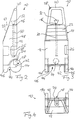
- a container 10 for storage is shown schematically in FIG. Transporting and dispensing liquid, in particular Irrigation water, shown.
- the container 10 has a hollow body unit 12, which in principle is cuboid and a cross-sectional area that tapers linearly upwards having.
- a handle 20 is formed, which is designed so that in A handle is created in the upper area, which is ergonomic the correct height for the average person.
- the container 10 is designed so that the Center of gravity of the filled container 10 relatively far below is easy to transport and good stability is possible.
- On the underside 44 of the container 10 are parallel spaced two vehicle roles in the side area 14 rotatably arranged about a common axis of rotation 42. These vehicle rollers 14 are used to transport the container 10.
- the vehicle rollers run smoothly and can in particular made of solid rubber in the running area.
- the container 10 is formed on the underside so that two are spaced apart arranged projection units 46 are present, so that the container 10 in the vertical shown in Figure 1 Form can be safely parked, in that it is one hand on the projection units 46 and the spaced support existing vehicle rollers 14 to the projection unit can.
- the protrusion units 46 and the vehicle rollers 14 are arranged so spaced that the filled container stands very stable.
- the projection units 46 are integrally formed on the underside 44 of the container 12.
- the container 10 is formed on a side wall 48 so that a handle 26 is formed.
- the container 10 with one hand of the operator from the vertical into the horizontal position and is therefore easy to carry.
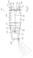
- the handle is diametrically opposite Side at the top of the container 10, d. H. in the Corner area of the handle 20, a pouring opening with pouring recesses 28 attached so that the container 10 also manually how to empty a normal watering can.
- hose 30 mounted at one end with a funnel 32, a filter screen, not shown and provided with a stop 38 at its other end is.
- the hose can be used to fill the container 10 30 via a guide ring, not shown, from the container 10 are pulled out to the stop 38.
- the container 10 next to a water point 50 the is shown schematically in FIG. 1 as a tap, so that then with the hose 30 and the fixed Funnel 32 the container 10 can be filled with water can.
- the built-in sieve, not shown, is easily removable trained and can be cleaned of floating materials become.
- the one not required in the hollow body unit 12 Condition existing hose 30 allows that no outside extra storage holder for the hose attached must become.
- the hose is designed so that the hose 30 from the container 10 by bending the Stop can also be removed and renewed can.
- the container 10 itself is preferably a plastic container manufactured so that an inexpensive manufacturing process by spraying or blowing.
- the container volume is designed so that it is for the respective Use case makes sense.
- the volume can range from approx. 20 l (Liter) fluctuate up to 50 l (liter).
- a container with larger volumes can be constructed easily.
- chamfered upper region 53 of the container 10 is a solar cell device 22 attached on the outside.
- the solar cell device 22 consists of individual solar cell elements or solar film elements. The attachment is designed so that it is permanent.
- the solar cell device 22 is by a not shown in the drawing circumferential bead of the container 10 protected from bumps.
- the size of the solar cell device 22 and the power is dimensioned in such a way that sufficient current is used is available.
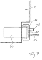
- the container 10 is prefabricated in the area of the outlet opening 18, that with a simple and waterproof union nut 52 the pressure pump 24 is inserted into the container 10 and can be screwed tight. By this measure is supported by additional sealing inserts permanent and reliable and leakproof attachment of the liquid pump possible, while at the same time easy disassembly is guaranteed for exchange purposes.
- the pump 24 is with power cables shown separately schematically in Figure 1 54 via a switching unit 56 to the solar cell device 22 connected.
- the power cables 54 are attached to the container 10 that the use is not affected.
- the pump 24 is from their output so dimensioned that on the one hand the solar cell device 22 provides the corresponding performance and on the other the water pressure is sufficient to empty the container 10 and to offer an optimal operating pressure.
- On the outside Part of the pump 24 has a flange 58 attached to it which is a flexible hose 34 that when emptying the guide the liquid to be emptied is attached can. The connection can be guaranteed by a push-on connection become.
- This correspondingly long flexible hose 34 is with a Nozzle 36 provided so that the liquid is convenient and light and especially also when keeping up at their place of use, like the garden, the grave or something else can be.
- the pump 24 is preferred by the switch unit 56 is designed as a toggle switch, and in the upper area of the Container 10 is placed in or put out of operation. This cable connection is also laid on the container 10, that safe use is given.
- the container 10 can so in terms of its own weight be constructed so that it can easily be used in the respective locations can be transported. Especially the handle, which allows the use as a "watering can” it, the container according to the invention easily for the purposes of his Transport to the respective site.
- the container 10 according to the invention can also in particular Leisure and camping area used as a water transporter become. This allows the water to be easily transported over long distances and well kept and easily removed become.
- the container 10 according to the invention is also for drinking water supply suitable for example in emergency areas, in a decentralized water supply should. There are particularly large refugee camps Water distribution problems due to large water collection vehicles usually only have a few delivery points.
- the container 10 according to the invention has a solar-powered one Cooling unit on that over the solar cell device 22 is supplied with power and installed on the container 10 is so that the food is cooled drinking water and is kept fresh.
- the retrofit of the invention is for the leisure area Container 10 in a shower device 40 according to FIG. 5 possible, which is very easy to use.
- Preferred by one Conical bracket 62 becomes the shower device 40 by means of a locking screw 64 in the upper area attached to the side of the handle 20 and fixed in position.
- the locking screw 64 is inserted into the opening a stable rod 66 is introduced, the one in the upper area Has holder for receiving the hose 34.
- the shower device 40 By inserting the hose 34 into the holder 62 of the rod 66 creates a shower device 40, depending on the body size can be adjusted by the locking screw 64.
- the shower device 40 can be arranged at the end Nozzle 36 or operated with a normal caster, so that an individual setting is possible.
- the solar powered pump 24 secures the water supply and provides the necessary pressure for the shower process.
- the container is equipped with a suction pump. This is for example necessary in the scope if for example Garden owners do not have a tap available, but get their water from lakes, rivers or streams, for example.
- the container according to the invention is a very use-oriented one Construction that is inexpensive to manufacture and ensures permanent and reliable use. Solar energy is used to be inexpensive and environmentally friendly to provide a pouring container, that can be used in many ways.
- not shown of the container according to the invention are the vehicle roles of dimensioned in such a way that easily predetermined or predefinable step heights when transporting the container can be overcome.
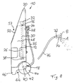
- FIG. 8 There is a difference in the container 10 shown in FIG. 8 a flexible hose to the container according to FIG. 2 76 with a spray head 74 in the lower area of the container 10 connected.
- the same components have the same reference numerals like the components of FIG. 2 and will not be repeated explained.
- the liquid pump device as a two-part device formed with a first liquid pump unit 70, the lower area inside the container 10 is arranged and to which the flexible hose 76 is connected and with a second liquid pump unit 72 present in the area of the spray head 74 and is not shown in detail.
- the flexible hose 76 is on a holding unit 78 releasably attachable to the container 10, the Holding unit 78 is designed so that when attached Spray head 74 which is directed essentially upwards.
- the first Liquid pump unit 70 switches when the spray head 74 is held inclined downward (position A in Fig. 8th; shown in dashed lines). In this position of the spray head the first liquid pump unit 70 is supplied with current and pumps water out of the inside of the container. As soon as the spray head is taken up (position B in Fig. 8; shown in dashed lines), the power supply becomes first liquid pump unit 70 interrupted. Thereby a pleasant pouring process can be accomplished without that awkward to pour or to turn off the water Switching units located on the container are actuated Need to become. In addition, the operating position when casting depending on the length of the flexible Hose 76 be away from the container.
- the container can either be filled using a suction pump or through the funnel through a tap.
- a level indicator unit through which the filling can be observed and which the shows the respective filling quantity.
- the solar unit removably attached to the housing.
- the standard type is powered by accumulators, which are preferred are rechargeable.
- the solar unit is available as an additional module, for example in a prefabricated one Recesses on the housing is clipped and in addition connected to the battery.
Abstract
Description
Die vorliegende Erfindung betrifft ein Behältnis zum Speichern, Transportieren und Ausbringen von Flüssigkeit, insbesondere Gießwasser oder Trinkwasser, mit einer Hohlkörpereinheit, unterseitig an der Hohlkörpereinheit vorhandenen Fahrzeugrollen, einer Einlaßöffnung, einer Auslaßöffnung und einer Handhabe zum rollenden Ziehen des Behältnis.The present invention relates to a container for storage, Transporting and dispensing liquid, in particular Pouring water or drinking water, with a hollow body unit, vehicle rollers on the underside of the hollow body unit, an inlet opening, an outlet opening and a handle for rolling pulling the container.
Das Gießen in den normalen Gießkannen mit zum Beispiel 10 oder 15 l (Liter) Inhalt erfordert einen relativ hohen Kraftaufwand und ist sehr beschwerlich. Für schwache oder ältere Menschen ist dies oft eine kaum zu lösende Aufgabe, insbesondere dann, wenn die Wasserstelle vom Einsatzort weit entfernt ist. Diese Aufgabe ist vielfältig anzutreffen, zum Beispiel im häuslichen Gartenbereich, in Schrebergärten, auf Friedhöfen, aber auch im landwirtschaftlichen oder gärtnerischen Bereich.Pouring in normal watering cans with 10 for example or 15 l (liter) of content requires a relatively high level of effort and is very difficult. For weak or elderly This is often a difficult task for humans, especially then when the water point is far away from the place of use is. This task can be found in many different ways, for example in the home garden area, in allotments, in cemeteries, but also in the agricultural or horticultural sector.
In dem deutschen Gebrauchsmuster G 91 04 697.1 ist eine Gießkanne beschrieben, die sich dadurch auszeichnet, daß Fahrrollen vorhanden sind, die in dem Kannenausguß gegenüberliegenden Endbereich der Kannenunterkörperseite angeordnet sind und der Kannenausguß verlängert als Betätigungshebel ausgebildet ist. Durch diese Maßnahme wird die Handhabung bzw. der Transport der Gießkanne verbessert. Jedoch bleibt das Problem, daß die Gießkanne zum Gießen angehoben werden muß, so daß auch hier beim Gießvorgang selbst ein erhöhter Kraftaufwand erforderlich ist. Darüber hinaus ist der Kannenausguß relativ lang gestaltet, so daß dieser beim Gießen entweder abgenommen werden muß oder infolge seiner Länge beim Gießen hinderlich ist.In the German utility model G 91 04 697.1 there is a watering can described, which is characterized in that casters are present, which are opposite in the can spout End region of the lower can side are arranged and the can spout extended as an operating lever is. This measure makes handling or transport the watering can improved. However, the problem remains that the watering can must be raised for watering, so that too increased effort is required here during the casting process itself is. In addition, the can spout is relatively long designed so that these can either be removed during casting must or is a hindrance to casting due to its length.
Der vorliegenden Erfindung liegt das technische Problem bzw. die Aufgabe zugrunde, ein gegenüber dem genannten Stand der Technik verbessertes Behältnis der eingangs genannten Art anzugeben, das einen einfachen Aufbau aufweist, einen leichten Transport gewährleistet und das Gießen oder Wasserentnehmen leicht und effektiv gestaltet.The present invention has the technical problem or based on the task of a compared to the state of the art To specify technology-improved container of the type mentioned at the outset, which has a simple structure, a light one Transport ensured and pouring or taking water designed light and effective.
Das erfindungsgemäße Behältnis ist durch die Merkmale des unabhängigen
Anspruchs 1 gegeben. Vorteilhafte Ausgestaltungen
und Weiterbildungen sind Gegenstand der abhängigen Ansprüche.The container according to the invention is characterized by the features of the
Das erfindungsgemäße Behältnis zum Speichern, Transportieren und Ausbringen von Flüssigkeit zeichnet sich demgemäß dadurch aus, daß außenseitig an dem Behältnis eine Solarzelleneinrichtung angeordnet ist, eine Flüssigkeitspumpeneinrichtung vorhanden ist zum bedarfsweise Abpumpen oder Ansaugen der im Inneren der Hohlkörpereinheit gespeicherten bzw. zu speichernden Flüssigkeit und die Solarzelleneinrichtung ihre erzeugte elektrische Leistung zumindest teilweise an die Flüssigkeitspumpeneinrichtung abgibt.The container according to the invention for storing, transporting and application of liquid is accordingly characterized from that on the outside of the container a solar cell device is arranged, a liquid pump device is available for pumping or sucking in the Inside the hollow body unit stored or to be stored Liquid and the solar cell device its generated electrical power at least partially to the liquid pump device delivers.
Bevorzugt wird für das Behältnis ein leichter Kunststoffbehälter eingesetzt, wobei auf eine besondere Leichtgängigkeit der Räder zu achten ist. Dadurch kann die Flüssigkeit (Wasser) mit geringem Kraftaufwand transportiert werden. Gleichzeitig wird das Tragen der schweren Flüssigkeitslast sowohl beim Transportvorgang als auch beim Gießvorgang umgangen und der Körper wird durch den Wegfall der einseitigen Belastung geschont. A light plastic container is preferred for the container used, with a particular ease of movement the wheels must be observed. This allows the liquid (water) can be transported with little effort. At the same time will carry the heavy fluid load both bypassed during the transport process as well as during the casting process and the body becomes obsolete due to the loss of one-sided stress spared.
Eine besonders bevorzugte Ausgestaltung des erfindungsgemäßen Behältnis zeichnet sich dadurch aus, daß im Einlaßbereich ein bis zu einem Anschlag aus der Hohlkörpereinheit herausziehbarer flexibler Schlauch vorhanden ist. Dadurch wird eine leichte Befüllung ermöglicht. Der flexible Schlauch wird aus dem Behälter herausgezogen und kann zum Befüllen leicht an die Wasserstelle bzw. den Wasserhahn herangeführt werden. In einer weiteren Ausgestaltung ist im Schlauch ein herausnehmbares Sieb angebracht, damit Schwimmstoffe ferngehalten werden.A particularly preferred embodiment of the invention Container is characterized in that in the inlet area can be pulled out of the hollow body unit up to a stop flexible hose is available. This will make one allows easy filling. The flexible hose is made pulled out of the container and can easily be filled the water point or the tap are brought up. In Another embodiment is a removable in the hose Strainer attached to keep floating materials away.
Die Hohlkörpereinheit weist ein Volumen im Bereich von 20 bis 40 l (Liter), insbesondere ca. 35 l (Liter) auf.The hollow body unit has a volume in the range from 20 to 40 l (liter), in particular approx. 35 l (liter).
Eine besonders flexible Ausgestaltung des erfindungsgemäßen Behältnis zeichnet sich dadurch aus, daß das Behältnis einen Tragegriff und diametral zu dem Tragegriff angeordnete Gießausnehmungen, insbesondere im Eckbereich der Handhabe, vorhanden sind, so daß das Behältnis wie eine Gießkanne zum Gießen benutzt werden kann.A particularly flexible embodiment of the invention Container is characterized in that the container has a Carrying handle and casting recesses arranged diametrically to the carrying handle, especially in the corner area of the handle are so that the container is like a watering can for watering can be used.
Als Solarzelleneinrichtung werden Solarzellen der handelsüblichen Art eingesetzt, die den notwendigen und ausreichenden Strom für die eingebaute Flüssigkeitspumpeneinrichtung liefern. Der Strom wird über eingebaute Kabel direkt zur Pumpe geliefert. Die Pumpe kann als Druckpumpe oder als Saugpumpe ausgebildet sein. Eine Druckpumpe wird eingesetzt, wenn die Flüssigkeit zum Gießen bzw. zum Entnehmen verwendet wird. Eine zusätzliche Saugpumpe wird eingesetzt, falls Wasser von einer Entnahmestelle angesaugt werden muß.As a solar cell device, solar cells are commercially available Kind used that the necessary and sufficient Supply electricity for the built-in liquid pump device. The current is directly to the pump via built-in cables delivered. The pump can be used as a pressure pump or as a suction pump be trained. A pressure pump is used when the Liquid is used for pouring or removing. An additional suction pump is used if water from a sampling point must be sucked in.
Eine besonders bevorzugte Ausgestaltung des erfindungsgemäßen Behältnis zeichnet sich dadurch aus, daß die Solarzelleneinrichtung ihre elektrische Leistung an eine Stromspeichereinheit abgibt, an die die Flüssigkeitspumpeneinrichtung angeschlossen ist. Dadurch steht jederzeit eine ausreichende Menge an elektrischer Energie zur Verfügung, die im Bedarfsfalle beispielsweise durch Betätigung einer einfachen Schaltereinrichtung angefordert werden kann.A particularly preferred embodiment of the invention Container is characterized in that the solar cell device their electrical power to a power storage unit emits to which the liquid pump device is connected is. This means that there is always an adequate one Amount of electrical energy available when needed for example by operating a simple switch device can be requested.
Durch Zusatzausstattungen ist das erfindungsgemäße Behältnis noch vielseitig neben dem Garten- und Friedhofsbereich auch im Freizeitbereich und zur Sicherung der Trinkwasserversorgung einsetzbar. So ist es möglich, mittels einer entsprechenden Haltevorrichtung eine Duschvorrichtung anzuschließen oder ein Aggregat zur Kühlung des Behälterinhaltes über die Solarzelleneinrichtung mit Strom zu versorgen, damit die Möglichkeit zur Trinkwasserversorgung beispielsweise in der dritten Welt möglich ist. Darüber hinaus kann auch wie bereits oben erwähnt der Einsatz einer solarbetriebenen Saugpumpe vorgesehen werden, damit der Behälter auch zum Beispiel aus Trögen oder Wasserläufen gefüllt werden kann.The container according to the invention is provided with additional equipment still versatile in addition to the garden and cemetery area in the leisure area and to secure the drinking water supply applicable. So it is possible by means of an appropriate Holding device to connect a shower device or an aggregate for cooling the contents of the container To supply solar cell device with electricity, thus the possibility for drinking water supply, for example in the third world is possible. In addition, it can be done as already mentioned above the use of a solar powered suction pump be provided so that the container for example can be filled from troughs or watercourses.
Ebenso können in der Hohlkörpereinheit Vorrichtungen zur Mischung des Behälterinhaltes vorgesehen werden, die von der Solarzelleneinrichtung mit Strom versorgt werden, damit auch ein aus verschiedenen Komponenten bestehender Behälterinhalt homogen vermischt werden kann.Devices for mixing can also be used in the hollow body unit of the container contents are provided by the Solar cell device can be powered, so too a container consisting of various components can be mixed homogeneously.
Eine bevorzugte Ausgestaltung des erfindungsgemäßen Behältnisses zeichnet sich dadurch aus, daß die Flüssigkeitspumpeneinrichtung eine erste Flüssigkeitspumpeneinheit zum Abpumpen und eine zweite Flüssigkeitspumpeneinheit zum Ansaugen aufweist, wobei sich eine weitere Ausgestaltung dadurch auszeichnet, daß die erste Flüssigkeitspumpeneinheit in oder am Gehäuse und die zweite Flüssigkeitspumpeneinheit im Bereich des freien Endes eines flexiblen, mit dem Inneren des Gehäuses kommunizierenden Schlauches angeordnet ist.A preferred embodiment of the container according to the invention is characterized in that the liquid pump device a first liquid pump unit for pumping and has a second liquid pump unit for suction, Another embodiment is characterized by that the first liquid pump unit in or on Housing and the second liquid pump unit in the area the free end of a flexible, with the inside of the housing communicating hose is arranged.
Bevorzugt sind die Flüssigkeitspumpeneinheiten jeweils als eine Kreiselpumpe ausgebildet. Das Anordnen von jeweils einer Kreiselpumpe für das Pumpen und einer zweiten Kreiselpumpe für das Saugen bringt eine dauerhaft zuverlässige Funktion im Hinblick auf die durch die Sonnenenergie gewonnene Antriebsenergie beziehungsweise die dadurch umzusetzende Stromstärke. Die erste Kreiselpumpe zum Entleeren des Behälters befindet sich im Behälter selbst und ist so gestellt, daß der Pumpenkreisel den Behälter entleert. Bei diesem Vorgang wird das Wasser aus dem Behälter durch die Kreiselpumpe in einen Entleerungsschlauch gedrückt. Die zweite Kreiselpumpe zum Befüllen des Behälters sitzt am freien Endbereich des flexiblen Entleerungsschlauchs und ist so eingebaut, daß durch die Kreiselpumpenbewegung das Wasser angesaugt und in den Behäl-ter gedrückt wird. Beide Pumpen sind so konstruiert, daß beim Entleerungsvorgang das Wasser durch die saugende Pumpe ohne Widerstand hindurchströmen kann. Beim Saugbetrieb wird das Wasser dann durch die abpumpende Pumpe ebenfalls ohne Widerstand durchgedrückt und gelangt so in den Behälter. Durch die Verwendung von zwei Kreiselpumpen ist es möglich, von einer Pumpe die Flüssigkeit durch die andere, ohne zusätzlichen Kraftaufwand zu pumpen.The liquid pump units are each preferred as a centrifugal pump is formed. Arranging one at a time Centrifugal pump for pumping and a second centrifugal pump for suction brings a permanently reliable function in the With regard to the drive energy obtained from solar energy or the current intensity to be implemented thereby. The first centrifugal pump for emptying the container is located itself in the container and is placed so that the pump gyro emptied the container. In this process it will Water from the tank through the centrifugal pump into a drain hose pressed. The second centrifugal pump for filling of the container sits at the free end area of the flexible Drain hose and is installed so that by the Centrifugal pump sucked the water and into the container is pressed. Both pumps are designed so that the Drain the water through the suction pump without Resistance can flow through. In suction mode it will Water then also pumped through the pump without resistance pushed through and gets into the container. Through the Using two centrifugal pumps it is possible to use one Pump the liquid through the other without additional Pumping effort.
Eine besonders bevorzugte Ausgestaltung des erfindungsgemäßen Behältnisses zeichnet sich dadurch aus, daß im Bereich des freien Endes eines mit dem Inneren des Gehäuses kommunizierenden Schlauches eine Neigungsschalteinheit vorhanden ist, wobei die Flüssigkeitspumpeneinrichtung beziehungsweise die Flüssigkeitspumpeneinheiten in Abhängigkeit der Neigung der Neigungsschalteinheit schaltbar sind.A particularly preferred embodiment of the invention Container is characterized in that in the area of free end of a communicating with the inside of the housing Hose an inclination switch unit is present, the liquid pump device or the Liquid pump units depending on the inclination of the Tilt switch unit are switchable.
Bevorzugt ist der Endbereich des Schlauches als Sprühkopf ausgebildet, in dem die Neigungsschalteinheit angebracht ist. Die Neigungsschalteinheit wird hierbei so angeordnet, daß sich der Stromkreis zum Betreiben beispielsweise der ersten Flüssigkeitspumpeneinheit erst dann schließt, wenn der Sprühkopf von der senkrechten beziehungsweise aus der waagerechten Lage nach unten geneigt wird. Erst dann wird der Stromkreis geschlossen und der Pumpenbetrieb kann laufen. Dabei wird zuverlässig verhindert, daß durch ungewolltes Inbetriebsetzen durch einen Hauptschalter am Gehäuse auf Startstellung sich der Behälter entleert, ohne daß dies gewünscht wird. Sofern der Sprühkopf ordnungsgemäß am Behälter angebracht ist, ist eine Entleerung nicht möglich.The end region of the hose is preferred as a spray head trained in which the tilt switch unit is attached. The tilt switch unit is arranged so that the circuit for operating the first, for example Liquid pump unit only closes when the spray head from the vertical or from the horizontal Position is inclined downwards. Only then will the circuit closed and the pump can run. It becomes reliable prevents accidental start-up by a main switch on the housing to the start position the container is emptied without this being desired. Provided the spray head is properly attached to the container emptying not possible.
In der Regel wird somit die abpumpende Pumpe immer dann geschaltet, wenn der Sprühkopf nach unten zeigt.As a rule, the pumping pump is always switched on when the spray head is facing down.
Insbesondere wird damit eine vorteilhafte Bedienung des Behältnisses als solches gewährleistet, da beim Sprühen oder Gießen beispielsweise von Pflanzen dieser Vorgang nicht mit dem Hauptschalter am Gehäuse unterbrochen werden muß, sondern das Ausbringen von Wasser von der Neigung der Neigungsschaltereinheit bestimmt wird. Neigt man diese nach unten, wird das Wasser ausgebracht und richtet man diese nach oben, d. h. über die Waagerechte hinaus, dann wird durch den Neigungsschalter der Stromkreis unterbrochen und die Pumpe setzt aus. Dies ist sehr vorteilhaft und angenehm, da damit leicht der Sprüh- oder Gießvorgang unterbrochen werden kann. Auch muß man sich nicht zum Gießen in engem Abstand vom Behältnis befinden.In particular, this is an advantageous operation of the container guaranteed as such since when spraying or Do not water this process with plants, for example the main switch on the housing must be interrupted, but discharging water from the tilt of the tilt switch unit is determined. Tilting it down will spread the water and point it upwards, d. H. beyond the horizontal, then through the tilt switch the circuit is interrupted and the pump stops. This is very advantageous and pleasant because it makes it easy Spraying or pouring can be interrupted. Also must one is not close to the container for pouring.
Weitere Ausführungsformen und Vorteile der Erfindung ergeben sich durch die in den Ansprüchen ferner aufgeführten Merkmale sowie durch die nachstehend angegebenen Ausführungsbeispiele. Die Merkmale der Ansprüche können in beliebiger Weise miteinander kombiniert werden, insoweit sie sich nicht offensichtlich gegenseitig ausschließen.Further embodiments and advantages of the invention result themselves by the features listed in the claims and by the exemplary embodiments specified below. The features of the claims can be related to one another in any way be combined as far as they are not obvious exclude each other.
Die Erfindung sowie vorteilhafte Ausführungsformen und Weiterbildungen derselben werden im folgenden anhand der in der Zeichnung dargestellten Beispiele näher beschrieben und erläutert. Die der Beschreibung und der Zeichnung zu entnehmenden Merkmale können einzeln für sich oder zu mehreren in beliebiger Kombination erfindungsgemäß angewandt werden. Es zeigen:
- Fig. 1
- schematische Seitenansicht eines Behältnisses mit flexiblem Einfüllschlauch und flexiblem Auslaßschlauch mit einer Druckpumpe,
- Fig. 2
- Seitenansicht des Behältnis gemäß
Figur 1 ohne die flexiblen Schläuche, - Fig. 3
- Vorderansicht des Behältnis gemäß Figur 2,
- Fig. 4
- Draufsicht auf das Behältnis gemäß Figur 2,
- Fig. 5
- schematische Ansicht eines Behältnis mit angeschlossener Duschvorrichtung,
- Fig. 6
- schematische Ansicht des Einsatzes eines Behältnis gemäß Figur 2 als Gießkanne,
- Fig. 7
- schematische Detailansicht im Anschlußbereich der Druckpumpe und
- Fig. 8
- schematische Seitenansicht eines Behältnis mit zwei Flüssigkeitspumpeneinheiten.
- Fig. 1
- schematic side view of a container with flexible filling hose and flexible outlet hose with a pressure pump,
- Fig. 2
- Side view of the container according to Figure 1 without the flexible hoses,
- Fig. 3
- Front view of the container according to Figure 2,
- Fig. 4
- Top view of the container according to FIG. 2,
- Fig. 5
- schematic view of a container with connected shower device,
- Fig. 6
- schematic view of the use of a container according to FIG. 2 as a watering can,
- Fig. 7
- schematic detailed view in the connection area of the pressure pump and
- Fig. 8
- schematic side view of a container with two liquid pump units.
In Figur 1 ist schematisch ein Behältnis 10 zum Speichern,
Transportieren und Ausbringen von Flüssigkeit, insbesondere
Gießwasser, dargestellt. Das Behältnis 10 weist eine Hohlkörpereinheit
12 auf, die im Prinzip quaderförmig ausgebildet
ist und einen nach oben sich linear verjüngenden Querschnittsbereich
aufweist. An die Hohlkörpereinheit 12 ist
eine Handhabe 20 angeformt, die so ausgebildet ist, daß im
oberen Bereich ein Handgriff entsteht, der in ergonomisch
richtiger Höhe für den Durchschnittsmenschen angeordnet ist.
Das Behältnis 10 ist insgesamt so ausgebildet, daß der
Schwerpunkt des gefüllten Behältnis 10 relativ weit unten
liegt, damit ein leichter Transport und eine gute Standsicherheit
möglich ist. Auf der Unterseite 44 des Behältnis 10
sind parallel beabstandet im Seitenbereich zwei Fahrzeugrollen
14 um eine gemeinsame Drehachse 42 drehbar angeordnet.
Diese Fahrzeugrollen 14 dienen zum Transport des Behältnis
10. Die Fahrzeugrollen sind leichtgängig und können insbesondere
aus Vollgummi im Laufbereich bestehen. Das Behältnis 10
ist unterseitig so ausgeformt, daß zwei beabstandet zueinander
angeordnete Vorsprungseinheiten 46 vorhanden sind, so daß
das Behältnis 10 in der in Figur 1 dargestellten senkrechten
Form sicher abgestellt werden kann, dadurch, daß es sich einerseits
auf die Vorsprungseinheiten 46 und die beabstandet
zur Vorsprungseinheit vorhandenen Fahrzeugrollen 14 abstützen
kann. Die Vorsprungseinheiten 46 und die Fahrzeugrollen 14
sind dabei so beabstandet angeordnet, daß das gefüllte Behältnis
sehr standsicher steht. Die Vorsprungseinheiten 46
sind an die Unterseite 44 des Behältnis 12 einstückig angeformt.A
Das Behältnis 10 ist an einer Seitenwandung 48 so ausgeformt,
daß ein Tragegriff 26 entsteht. Damit kann das Behältnis 10
mit einer Hand der Bedienperson aus der Senkrechten in die
horizontale Lage gebracht werden und ist somit leicht tragbar.
Gemäß Figur 6 ist an der dem Tragegriff diametral gegenüberliegenden
Seite am oberen Ende des Behältnis 10, d. h. im
Eckbereich der Handhabe 20, eine Ausgießöffnung mit Gießausnehmungen
28 angebracht, so daß das Behältnis 10 auch manuell
wie eine normale Gießkanne entleert werden kann.The
Zur Befüllung des Behältnis 10 ist unterhalb der Handhabe 20
in der Behältermitte im Bereich einer Einlaßöffnung 16 ein
flexibler Schlauch 30 montiert, der an seinem einen Ende mit
einem Trichter 32, einem nicht näher dargestellten Filtersieb
und an seinem anderen Ende mit einem Anschlag 38 versehen
ist. Dadurch kann zur Befüllung des Behältnis 10 der Schlauch
30 über einen nicht dargestellten Führungsring aus dem Behältnis
10 bis zum Anschlag 38 herausgezogen werden. Zum Befüllen
ist das Behältnis 10 neben einer Wasserstelle 50, die
in Figur 1 als Wasserhahn schematisch dargestellt ist, abzustellen,
so daß dann mit dem Schlauch 30 und dem festmontierten
Trichter 32 das Behältnis 10 mit Wasser gefüllt werden
kann. Das nicht dargestellte eingebaute Sieb ist leicht herausnehmbar
ausgebildet und kann von Schwimmstoffen gereinigt
werden. Der in der Hohlkörpereinheit 12 im nicht benötigten
Zustand vorhandene Schlauch 30 ermöglicht, daß keine außenanliegende
extra Aufbewahrungshalterung für den Schlauch angebracht
werden muß. Dabei ist der Schlauch so ausgebildet, daß
der Schlauch 30 aus dem Behältnis 10 durch das Verbiegen des
Anschlags auch insgesamt herausgenommen und erneuert werden
kann.For filling the
Das Behältnis 10 selbst wird bevorzugt als Kunststoffbehälter
hergestellt, so daß ein kostengünstiges Herstellungsverfahren
im Spritzverfahren oder Blasverfahren möglich ist. Hierbei
ist das Behältervolumen so ausgelegt, daß es für den jeweiligen
Einsatzfall sinnvoll ist. Das Volumen kann von ca. 20 l
(Liter) bis 50 l (Liter) schwanken. Auch ein Behältnis mit
größerem Volumen kann problemlos konstruiert werden. In dem
abgeschrägten oberen Bereich 53 des Behältnis 10 ist eine Solarzelleneinrichtung
22 außenseitig angebracht. Die Solarzelleneinrichtung
22 besteht aus einzelnen Solarzellenelementen
oder Solarfolienelementen. Dabei ist die Befestigung so ausgebildet,
daß sie dauerhaft ist. Die Solarzelleneinrichtung
22 wird durch einen in der Zeichnung nicht näher dargestellten
umlaufenden Wulst des Behältnisses 10 vor Stößen geschützt.
Die Größe der Solarzelleneinrichtung 22 und die Leistung
wird so dimensioniert, daß genügend Strom zur Anwendung
zur Verfügung steht. The
Auf der gegenüberliegenden Seite der Solarzelleneinrichtung
22 ist im unteren Bereich des Behältnis 10 im Bereich einer
Auslaßöffnung 18 eine Flüssigkeitspumpe 24 vorhanden, die als
Druckpumpe ausgebildet ist.On the opposite side of the
Im Bereich der Auslaßöffnung 18 ist das Behältnis 10 so vorgefertigt,
daß mit einer einfachen und wasserdichten Überwurfmutter
52 die Druckpumpe 24 in das Behältnis 10 eingeführt
und festgeschraubt werden kann. Durch diese Maßnahme
unterstützt durch zusätzlich dichtende Einlagen ist eine
dauerhafte und zuverlässige und dichte Befestigung der Flüssigkeitspumpe
möglich, wobei gleichzeitig eine einfache Demontage
zu Austauschzwecken gewährleistet wird. Die Pumpe 24
wird mit in Figur 1 separat schematisch dargeführten Stromkabeln
54 über eine Schalteinheit 56 an die Solarzelleneinrichtung
22 angeschlossen.The
Die Stromkabel 54 werden so am Behältnis 10 befestigt, daß
die Nutzung nicht beeinträchtigt wird. Die Pumpe 24 wird von
ihrer Leistung so bemessen, daß einerseits die Solarzelleneinrichtung
22 die entsprechende Leistung liefert und zum anderen
der Wasserdruck ausreicht, das Behältnis 10 zu leeren
und einen optimalen Einsatzdruck zu bieten. An dem außenliegenden
Teil der Pumpe 24 ist ein Flansch 58 angebracht, auf
dem ein flexibler Schlauch 34, der beim Entleeren der Führung
der zu entleerenden Flüssigkeit dient, angebracht werden
kann. Die Verbindung kann durch eine Aufsteckverbindung gewährleistet
werden.The
Dieser entsprechend lange flexible Schlauch 34 ist mit einer
Düse 36 versehen, so daß die Flüssigkeit bequem und leicht
und insbesondere auch bei Aufrechthaltung an ihrem Einsatzort,
wie zum Beispiel den Garten, das Grab oder anderes herangebracht
werden kann. This correspondingly long
Die Pumpe 24 wird durch die Schaltereinheit 56, die bevorzugt
als Kippschalter ausgebildet ist, und im oberen Bereich des
Behältnis 10 angeordnet ist in bzw. außer Betrieb gesetzt.
Auch diese Kabelverbindung wird so am Behältnis 10 verlegt,
daß eine sichere Nutzung gegeben ist.The
Das Behältnis 10 kann hinsichtlich seines Eigengewichts so
konstruiert werden, daß es problemlos zu den jeweiligen Einsatzorten
transportiert werden kann. Insbesondere der Tragegriff,
der den Einsatz als "Gießkanne" ermöglicht, erlaubt
es, das erfindungsgemäße Behältnis problemlos zu Zwecken seines
Einsatzes an den jeweiligen Einsatzort zu transportieren.The
Das erfindungsgemäße Behältnis 10 kann insbesondere auch im
Freizeit- und Campingbereich als Wassertransporter eingesetzt
werden. Damit kann leicht das Wasser über weite Strecken herantransportiert
und gut aufbewahrt sowie auch leicht entnommen
werden.The
Das erfindungsgemäße Behältnis 10 ist auch zur Trinkwasserversorgung
zum Beispiel in Notstandsgebieten geeignet, in
denen eine dezentrale Wasserversorgung aufgebaut werden
soll. Insbesondere kommt es in Flüchtlingslagern es zu großen
Problemen der Wasserverteilung, da große Wassersammelfahrzeuge
meist nur wenig Abgabestellen haben. In diesem Zusammenhang
weist das erfindungsgemäße Behältnis 10 ein solargetriebenes
Kühlaggregat auf, das über die Solarzelleneinrichtung
22 mit Strom versorgt wird und an dem Behältnis 10 eingebaut
ist, so daß das Lebensmittel Trinkwasser gekühlt wird
und in frischem Zustand erhalten wird.The
In den Figuren tragen gleiche Bauteile das gleiche Bezugszeichen und werden nicht nochmals erläutert.The same components have the same reference symbols in the figures and will not be explained again.
Für den Freizeitbereich ist die Umrüstung des erfindungsgemäßen
Behältnis 10 in eine Duschvorrichtung 40 gemäß Figur 5
möglich, die sehr leicht zu handhaben ist. Durch eine bevorzugt
konisch verlaufende Halterung 62 wird die Duschvorrichtung
40 mittels einer Feststellschraube 64 im oberen Bereich
seitlich an der Handhabe 20 aufgesteckt und in ihrer Lage fixiert.
Hierzu wird in die Öffnung der Feststellschraube 64
ein stabiler Stab 66 eingeführt, der im oberen Bereich eine
Halterung zur Aufnahme des Schlauches 34 aufweist.The retrofit of the invention is for the
Durch Einlegen des Schlauches 34 in die Halterung 62 des Stabes
66 entsteht eine Duschvorrichtung 40, die je nach Körpergröße
durch die Feststellschraube 64 eingestellt werden kann.
Die Duschvorrichtung 40 kann mittels einer endseitig angeordneten
Düse 36 oder mit einem normalen Gießer betrieben werden,
so daß eine individuelle Einstellung möglich ist. Die
solargetriebene Pumpe 24 sichert die Wasserversorgung und
sorgt für den notwendigen Druck für den Duschvorgang. Durch
das rechtzeitige Befüllen des Behältnis 10 und seiner Lagerung
zum Beispiel im Sonnenbereich kann sich der Behälterinhalt
so erwärmen, daß eine angenehme Wassertemperatur erreicht
wird.By inserting the
In einer nicht dargestellten Ausführungsvariante ist das Behältnis mit einer Saugpumpe ausgestattet. Dies ist zum Beispiel in dem Anwendungsbereich notwendig, wenn zum Beispiel Gartenbesitzer keinen Wasserhahn zur Verfügung haben, sondern ihr Wasser zum Beispiel aus Seen, Flüssen oder Bächen gewinnen.In a variant, not shown, the container is equipped with a suction pump. This is for example necessary in the scope if for example Garden owners do not have a tap available, but get their water from lakes, rivers or streams, for example.
Das erfindungsgemäße Behältnis ist eine sehr gebrauchsorientierte Konstruktion, die kostengünstig herstellbar ist und einen dauerhaften und zuverlässigen Einsatz gewährleistet. Die Sonnenenergie wird eingesetzt, um kostengünstig und umweltfreundlich ein Gießbehältnis zur Verfügung zu stellen, das vielseitig genutzt werden kann. The container according to the invention is a very use-oriented one Construction that is inexpensive to manufacture and ensures permanent and reliable use. Solar energy is used to be inexpensive and environmentally friendly to provide a pouring container, that can be used in many ways.
In einer nicht dargestellten bevorzugten Ausführungsvariante des erfindungsgemäßen Behältnis sind die Fahrzeugrollen von ihrem Durchmesser her so bemessen, daß problemlos vorgegebene oder vorgebbare Stufenhöhen beim Transport des Behältnis überwunden werden können.In a preferred embodiment variant, not shown of the container according to the invention are the vehicle roles of dimensioned in such a way that easily predetermined or predefinable step heights when transporting the container can be overcome.
Neben der Versorgung der Pumpe mit Strom für den obengenannten Anwendungsbereich steht über eine separate Anschlußbuchse die Abgabe von Solarstrom zur Verfügung.In addition to supplying the pump with electricity for the above Area of application is via a separate connection socket the supply of solar power is available.
Damit können weitere externe Stromverbraucher betrieben werden, die sonst eine eigene Solarzelleneinrichtung benötigen würden. Dies können aus heutiger Sicht zum Beispiel sein: Teichpumpen, Solarlampen, Ventilatoren, Kühltaschen, Radios, Kleinkompressoren, Akkus und viele andere im Garten- und Freizeitbereich sowie gewerbliche Anwendungen.This means that additional external power consumers can be operated, who would otherwise need their own solar cell facility would. From today's perspective, these can be, for example: Pond pumps, solar lamps, fans, cool bags, radios, Small compressors, batteries and many others in the garden and Leisure area as well as commercial applications.
Bei dem in Fig. 8 dargestellten Behältnis 10 ist im Unterschied
zu dem Behältnis gemäß Fig. 2 ein flexibler Schlauch
76 mit einem Sprühkopf 74 im unteren Bereich an das Behältnis
10 angeschlossen. Gleiche Bauteile tragen dasselbe Bezugszeichen
wie die Bauteile gemäß Fig. 2 und werden nicht nochmals
erläutert.There is a difference in the
Als weiterer Unterschied ist bei der Ausführungsform gemäß
Fig. 8 die Flüssigkeitspumpeneinrichtung als zweiteilige Einrichtung
ausgebildet mit einer ersten Flüssigkeitspumpeneinheit
70, die im unteren Bereich im Inneren des Behältnisses
10 angeordnet ist und an die der flexible Schlauch 76 angeschlossen
ist, und mit einer zweiten Flüssigkeitspumpeneinheit
72, die im Bereich der Sprühkopfes 74 vorhanden und
nicht näher dargestellt ist. Another difference is in the embodiment according to
Fig. 8, the liquid pump device as a two-part device
formed with a first
Darüberhinaus ist der flexible Schlauch 76 an einer Halteeinheit
78 an dem Behältnis 10 lösbar befestigbar, wobei die
Halteeinheit 78 so ausgebildet ist, daß bei befestigtem
Sprühkopf 74 dieser im wesentlichen nach oben gerichtet ist.In addition, the
Innerhalb des Sprühkopfes 74 ist eine in Fig. 8 nicht näher
dargestellte Neigungsschalteinheit vorhanden, die die erste
Flüssigkeitspumpeneinheit 70 dann schaltet, wenn der Sprühkopf
74 nach unten geneigt gehalten wird (Position A in Fig.
8; gestrichelt dargestellt). In dieser Position des Sprühkopfes
wird die erste Flüssigkeitspumpeneinheit 70 mit Strom beaufschlagt
und pumpt Wasser aus dem Behältnisinneren heraus.
Sobald der Sprühkopf nach oben genommen wird (Position B in
Fig. 8; gestrichelt dargestellt), wird die Stromzufuhr zur
ersten Flüssigkeitspumpeneinheit 70 unterbrochen. Dadurch
läßt sich ein angenehmer Gießvorgang bewerkstelligen, ohne
daß zum Gießen beziehungsweise zum Abstellen des Wassers umständlich
am Behältnis befindliche Schalteinheiten betätigt
werden müssen. Darüberhinaus kann die Betätigungsposition
beim Gießen in Abhängigkeit von der Länge des flexiblen
Schlauches 76 entfernt vom Behältnis sein.Within the
Das Befüllen des Behältnisses kann entweder über eine Saugpumpe oder über einen Wasserhahn durch den Trichter erfolgen. Um eine Überfüllung zu vermeiden, weist eine nicht dargestellte Ausführungsvariante eine Füllstandsanzeigeeinheit auf, durch die die Füllung beobachtet werden kann und die die jeweilige Füllmenge anzeigt.The container can either be filled using a suction pump or through the funnel through a tap. In order to avoid overfilling, one not shown Design variant a level indicator unit through which the filling can be observed and which the shows the respective filling quantity.
Bei einer nicht dargestellten Ausführungsvariante ist die Solareinheit abnehmbar an dem Gehäuse angebracht. Der Standarttyp wird durch Akkumulatoren mit Strom versorgt, die bevorzugt wieder aufladbar ausgebildet sind. Die Solareinheit ist als zusätzlicher Modul lieferbar, der beispielsweise in vorgefertigte Vertiefungen am Gehäuse eingeclipst wird und zusätzlich an den Akku angeschlossen wird.In a variant not shown, the solar unit removably attached to the housing. The standard type is powered by accumulators, which are preferred are rechargeable. The solar unit is available as an additional module, for example in a prefabricated one Recesses on the housing is clipped and in addition connected to the battery.
Claims (18)
- A container (10) for storing, transporting and dispensing liquid, especially water for drinking or watering, witha hollow body unit (12),with vehicle rollers (14) present on the underside of the hollow body unit,with an inlet orifice (16),with an outlet orifice (18) andwith a handle for pulling the container (10) by rolling,
whereina solar cell device (22) is arranged on the outside of the container,there is a liquid pump device (24), for pumping off or sucking in, as required, the liquid stored or to be stored inside the hollow body unit (12), andthe solar cell device (22) transmits its generated electric power at least partially to the liquid pump device (24). - The container as claimed in claim 1, wherein the solar cell device transmits its electric power to a current storage unit, to which the liquid pump device is connected.
- The container as claimed in claim 1 and/or 2, wherein the container (10) has a carrying grip (26) and watering recesses (28) arranged diametrically to the carrying grip (26), especially in the corner region of the handle (20), so that the container (10) can be used as a watering can for watering.
- The container as claimed in one or more of the preceding claims, wherein, in the inlet region (16), there is a flexible hose (30) capable of being pulled out of the hollow body unit (12) as far as a stop.
- The container as claimed in claim 4, wherein the filling end of the hose (30) is of funnel-shaped design.
- The container as claimed in one or more of the preceding claims, wherein there is a refrigerating assembly, to which the solar cell unit at least partially transmits its electric energy, as required.
- The container as claimed in one or more of the preceding claims, wherein the container and/or the vehicle rollers consist of plastic.
- The container as claimed in one or more of the preceding claims, wherein a hose connection unit, especially for connecting a flexible hose (34), is arranged at the outlet orifice (18).
- The container as claimed in one or more of the preceding claims, wherein the handle designed as a grip unit is located at a height at which it can be grasped by the operator without difficulty.
- The container as claimed in one or more of the preceding claims, wherein -the hollow body unit has essentially a parallelepipedic shape.
- The container as claimed in one or more of the preceding claims, wherein the volume of the hollow body unit (12) is 20 to 50 l (liters), especially approximately 35 l (liters)
- The container as claimed in one or more of the preceding claims, wherein the container has a current connection unit which has current applied to it by the solar cell device and to which external current consumption units can be connected.
- The container as claimed in one or more of the preceding claims, wherein a shower unit can be fastened releasibly to the container.
- The container as claimed in one or more of the preceding claims, wherein the liquid pump device has a first liquid pump unit (70) for pumping off and a second liquid pump unit (72) for sucking in.
- The container as claimed in claim 14, wherein the first liquid pump unit (70) is arranged in or on the housing and the second liquid pump unit (72) is arranged in the region of the free end of the flexible hose (76) communicating with the interior of the housing.
- The container as claimed in claim 14 and/or 15, wherein the liquid pump units are designed in each case as centrifugal pump assemblies.
- The container as claimed in one or more of the preceding claims, wherein an inclination switch unit is present in the region of the free end of a hose communicating with the interior of the housing, the liquid pump device or the liquid pump units being capable of being switched in dependence on the inclination of the inclination switch unit.
- The container according to the preamble of claim 1, wherein- an accumulator unit is present,- a liquid pump device (24) is present for pumping off or sucking in, as required, the liquid stored or to be stored inside the hollow body unit (12), and- the accumulator unit transmits its generated electric power at least partially to the liquid pump device (24),- a bearing unit for the releasible fastening of a solar cell device is present on the hollow body unit.
Applications Claiming Priority (5)
| Application Number | Priority Date | Filing Date | Title |
|---|---|---|---|
| DE29500710U DE29500710U1 (en) | 1995-01-18 | 1995-01-18 | Container for storing, transporting and dispensing liquid, especially irrigation water or drinking water |
| DE29500710U | 1995-01-18 | ||
| DE29511629U | 1995-07-19 | ||
| DE29511629U DE29511629U1 (en) | 1995-01-18 | 1995-07-19 | Container for storing, transporting and dispensing liquids, especially irrigation water or drinking water |
| PCT/DE1996/000009 WO1996022013A1 (en) | 1995-01-18 | 1996-01-05 | Container for storing, transporting and dispensing liquid, especially water for drinking or watering |
Publications (2)
| Publication Number | Publication Date |
|---|---|
| EP0804064A1 EP0804064A1 (en) | 1997-11-05 |
| EP0804064B1 true EP0804064B1 (en) | 1999-03-24 |
Family
ID=26057502
Family Applications (1)
| Application Number | Title | Priority Date | Filing Date |
|---|---|---|---|
| EP96900250A Expired - Lifetime EP0804064B1 (en) | 1995-01-18 | 1996-01-05 | Container for storing, transporting and dispensing liquid, especially water for drinking or watering |
Country Status (5)
| Country | Link |
|---|---|
| US (1) | US5961048A (en) |
| EP (1) | EP0804064B1 (en) |
| AU (1) | AU4384496A (en) |
| ES (1) | ES2132869T3 (en) |
| WO (1) | WO1996022013A1 (en) |
Families Citing this family (25)
| Publication number | Priority date | Publication date | Assignee | Title |
|---|---|---|---|---|
| IT1288061B1 (en) * | 1996-12-17 | 1998-09-10 | Lorenzo Schia | DEVICE FOR SPRAYING LIQUID SUBSTANCES |
| IT1297575B1 (en) * | 1997-12-11 | 1999-12-17 | Calipso Srl | ELECTRIC POWER SYSTEM FOR SHOWER ENCLOSURES OR MULTI-FUNCTION EQUIPPED COLUMN |
| ITPA980005A1 (en) * | 1998-02-26 | 1999-08-26 | Giuseppe Fuca | CONTAINER ON WHEELS FOR AUTOMATIC IRRIGATION OF GARDEN AND APARTMENT POTS. |
| US6047898A (en) * | 1998-05-29 | 2000-04-11 | Alert Services, Inc. | Portable fountain |
| DE29916317U1 (en) * | 1999-09-16 | 1999-12-30 | Koch Ludwig | Movable storage device |
| DE10106463A1 (en) * | 2001-02-13 | 2002-08-14 | Hirschmann Laborgeraete Gmbh | Digital burette and method for displaying the dosing volume of such a digital burette |
| DE10123096C1 (en) * | 2001-05-08 | 2002-09-19 | Michael Schwenke | Spray head for garden hose has expanding diffuser nozzle on end of wand to reduce velocity of spray |
| US6981613B1 (en) * | 2002-12-06 | 2006-01-03 | Cullen Kamisugi | Portable pressurized liquid storage system |
| GB0317019D0 (en) * | 2003-07-23 | 2003-08-27 | Hancock John | A roller |
| US7418832B2 (en) * | 2003-10-21 | 2008-09-02 | William R Ferrono | Portable mister for adjusting ambient temperature |
| WO2006029477A1 (en) * | 2004-09-17 | 2006-03-23 | George Bito | Portable liquid dispensing apparatus |
| KR100678841B1 (en) | 2005-05-21 | 2007-02-05 | 이홍복 | Movable sprinkler |
| US7464735B2 (en) * | 2005-06-08 | 2008-12-16 | Kelcamax Innovations, Llc | Funnel stand with retractable hose |
| US20080203117A1 (en) * | 2007-02-26 | 2008-08-28 | Townsend Robert L | Fresh water tote a long |
| AT504339B8 (en) * | 2007-03-15 | 2008-09-15 | Schmidt Franz | WATERING |
| US7789329B2 (en) | 2008-04-29 | 2010-09-07 | Chapin Manufacturing, Inc. | Filtering apparatus for inlet fluid into a pressure chamber of a sprayer |
| US8714411B2 (en) | 2010-12-02 | 2014-05-06 | Back Road Ventures, Inc. | Portable fluid treatment and dispensing system |
| ITMO20120268A1 (en) * | 2012-10-31 | 2014-05-01 | Fabrizio Comastri | IRRIGATION SYSTEM. |
| CN102941174A (en) * | 2012-11-17 | 2013-02-27 | 陈海 | Electric atomizer |
| CA2847198C (en) | 2013-03-15 | 2021-06-08 | Chapin Manufacturing, Inc. | Clog retarding filtering apparatus for inlet fluid into a pressure chamber of a sprayer |
| DE102013009795A1 (en) * | 2013-06-12 | 2014-12-18 | Stephan Krüger | Device for filling watering cans |
| CN105660318A (en) * | 2016-04-08 | 2016-06-15 | 赵静 | Dual-tube water sprayer |
| CN106037562A (en) * | 2016-07-14 | 2016-10-26 | 殷永生 | Simple shower device |
| CN106376434A (en) * | 2016-08-29 | 2017-02-08 | 山东胜伟园林科技有限公司 | Video-scanning irrigating system based on Internet of Things |
| US11529024B2 (en) * | 2020-01-31 | 2022-12-20 | Outdoor Culture Inc. | Portable solar shower with vacuum insulated water tank |
Family Cites Families (19)
| Publication number | Priority date | Publication date | Assignee | Title |
|---|---|---|---|---|
| FR1453606A (en) * | 1965-11-09 | 1966-09-23 | Portable shower device for individual use | |
| CH557203A (en) * | 1972-08-31 | 1974-12-31 | Graef Helmut | GARDEN SPRAYER. |
| DE2404341A1 (en) * | 1974-01-30 | 1975-07-31 | Fischer & Co Industrieberatung | Container trolley for gardening or graveyard use - has two-wheeled chassis with non-spill container, mixing brooms and dipstick |
| US3940065A (en) * | 1975-03-14 | 1976-02-24 | Graco Inc. | Portable spraying apparatus |
| US3939503A (en) * | 1975-04-16 | 1976-02-24 | Nazworth Harold W | Portable emergency safety shower |
| US4269329A (en) * | 1978-05-19 | 1981-05-26 | Keller Terry M | Plant-watering device |
| DE2851793A1 (en) * | 1978-11-30 | 1980-06-12 | Ulrich Dipl Ing Luboschik | Solar shower bath-warm water collector - is connected to support and suspended grip with flexible drain hose containing distributor jets |
| US4567563A (en) * | 1980-12-30 | 1986-01-28 | Energy Management Corporation | Irrigation control system |
| US4700892A (en) * | 1986-10-10 | 1987-10-20 | Blue Mountain Products, Inc. | Misting and watering can |
| US4945672A (en) * | 1988-11-02 | 1990-08-07 | Raia John A | Water circulating and aerating device for live bait containers |
| DE8901123U1 (en) * | 1989-01-30 | 1989-03-23 | Gerdes Gmbh, 5014 Kerpen, De | |
| US5104016A (en) * | 1990-02-12 | 1992-04-14 | Bikestream, Inc. | Pressurized potable beverage drinking system |
| US5111538A (en) * | 1990-06-04 | 1992-05-12 | Chapman Donald L | Knockdown portable hotwater shower and shower head therefor |
| US5040726A (en) * | 1990-06-25 | 1991-08-20 | Dimitri Amir T | Solar energy powered water fountain |
| US5154317A (en) * | 1990-07-09 | 1992-10-13 | Roppolo Iii Michael A | Portable liquid dispenser |
| DE9104697U1 (en) * | 1991-04-17 | 1991-07-18 | Ellwart, Heinrich | |
| US5506565A (en) * | 1993-06-25 | 1996-04-09 | Andrew De Leon; Joseph | Device for signaling the felling of a tree and a system for forest conservation |
| US5484538A (en) * | 1993-09-14 | 1996-01-16 | Texavia International, Inc. | Multiple service water purifier and dispenser and process of purifying water |
| DE29500710U1 (en) * | 1995-01-18 | 1995-03-30 | Prieschl Herbert | Container for storing, transporting and dispensing liquid, especially irrigation water or drinking water |
-
1996
- 1996-01-05 AU AU43844/96A patent/AU4384496A/en not_active Abandoned
- 1996-01-05 ES ES96900250T patent/ES2132869T3/en not_active Expired - Lifetime
- 1996-01-05 EP EP96900250A patent/EP0804064B1/en not_active Expired - Lifetime
- 1996-01-05 WO PCT/DE1996/000009 patent/WO1996022013A1/en active IP Right Grant
- 1996-01-05 US US08/875,801 patent/US5961048A/en not_active Expired - Fee Related
Also Published As
| Publication number | Publication date |
|---|---|
| EP0804064A1 (en) | 1997-11-05 |
| US5961048A (en) | 1999-10-05 |
| ES2132869T3 (en) | 1999-08-16 |
| AU4384496A (en) | 1996-08-07 |
| WO1996022013A1 (en) | 1996-07-25 |
Similar Documents
| Publication | Publication Date | Title |
|---|---|---|
| EP0804064B1 (en) | Container for storing, transporting and dispensing liquid, especially water for drinking or watering | |
| DE602005000117T2 (en) | Drinking fountain for pets | |
| DE60218770T2 (en) | Tank construction for carpet cleaner | |
| DE4231826A1 (en) | Device for atomizing liquids | |
| DE69730875T2 (en) | Self-cleaning vacuum cleaner | |
| EP1010894A2 (en) | Pond insert with pump | |
| WO2009070902A1 (en) | Air humidifier having central opening for filling and water level-controlled closure element | |
| DE69908426T2 (en) | SELF-EMPTYING VACUUM CLEANER | |
| DE1958532A1 (en) | Vapor separator for the fuel tank of motor vehicles | |
| DE19629136A1 (en) | Control device for a feed pump or the like | |
| DE102018006973B3 (en) | Device for supplying and / or disposing of liquids in caravans and / or mobile homes | |
| WO2011009599A1 (en) | Mobile cleaning device | |
| DE202018003530U1 (en) | Arrangement for receiving a cleaning liquid | |
| DE10036462A1 (en) | Filling system for multiple containers has delivery unit and filling unit with number of outlets arranged so that liquid can flow into corresponding number of inflow openings in containers | |
| EP0297526B1 (en) | Wet-dry vacuum cleaner | |
| DE60110280T2 (en) | Construction of a vacuum container | |
| DE69721722T2 (en) | Combined vacuum and storage container | |
| EP0936329A2 (en) | Transportable heater | |
| DE3734458A1 (en) | Oil changing device | |
| EP2071940B1 (en) | Device for transporting and deploying liquid | |
| DE2517497A1 (en) | ELECTRIC COLLECTOR WITH A FILLING AND EXPANSION AREA COMMON TO ALL CELLS, WITH LEVELING DEVICE FOR THE ELECTROLYTE LIQUID IN THE CELL CONTAINERS | |
| DE3529604C2 (en) | Device for humidifying and / or cleaning air | |
| EP0804897A2 (en) | Floor cleaning machine, in particular vacuum scrubbing machine | |
| EP1069057B1 (en) | Receptacle for compostable materials | |
| DE202005019806U1 (en) | Waste oil e.g. lubricating oil, trapping/collecting device for e.g. passenger car, has vacuum pump to produce negative pressure in oil collecting container, where one inflow nozzle has control valve for its opening or closing |
Legal Events
| Date | Code | Title | Description |
|---|---|---|---|
| PUAI | Public reference made under article 153(3) epc to a published international application that has entered the european phase |
Free format text: ORIGINAL CODE: 0009012 |
|
| 17P | Request for examination filed |
Effective date: 19970724 |
|
| AK | Designated contracting states |
Kind code of ref document: A1 Designated state(s): DE ES FR GB IT |
|
| GRAG | Despatch of communication of intention to grant |
Free format text: ORIGINAL CODE: EPIDOS AGRA |
|
| 17Q | First examination report despatched |
Effective date: 19980209 |
|
| GRAG | Despatch of communication of intention to grant |
Free format text: ORIGINAL CODE: EPIDOS AGRA |
|
| GRAH | Despatch of communication of intention to grant a patent |
Free format text: ORIGINAL CODE: EPIDOS IGRA |
|
| GRAH | Despatch of communication of intention to grant a patent |
Free format text: ORIGINAL CODE: EPIDOS IGRA |
|
| GRAH | Despatch of communication of intention to grant a patent |
Free format text: ORIGINAL CODE: EPIDOS IGRA |
|
| GRAA | (expected) grant |
Free format text: ORIGINAL CODE: 0009210 |
|
| AK | Designated contracting states |
Kind code of ref document: B1 Designated state(s): DE ES FR GB IT |
|
| REF | Corresponds to: |
Ref document number: 59601500 Country of ref document: DE Date of ref document: 19990429 |
|
| ITF | It: translation for a ep patent filed |
Owner name: DE DOMINICIS & MAYER S.R.L. |
|
| GBT | Gb: translation of ep patent filed (gb section 77(6)(a)/1977) |
Effective date: 19990429 |
|
| ET | Fr: translation filed | ||
| REG | Reference to a national code |
Ref country code: ES Ref legal event code: FG2A Ref document number: 2132869 Country of ref document: ES Kind code of ref document: T3 |
|
| PLBE | No opposition filed within time limit |
Free format text: ORIGINAL CODE: 0009261 |
|
| STAA | Information on the status of an ep patent application or granted ep patent |
Free format text: STATUS: NO OPPOSITION FILED WITHIN TIME LIMIT |
|
| 26N | No opposition filed | ||
| REG | Reference to a national code |
Ref country code: GB Ref legal event code: IF02 |
|
| PGFP | Annual fee paid to national office [announced via postgrant information from national office to epo] |
Ref country code: GB Payment date: 20021212 Year of fee payment: 8 |
|
| PGFP | Annual fee paid to national office [announced via postgrant information from national office to epo] |
Ref country code: FR Payment date: 20030120 Year of fee payment: 8 |
|
| PGFP | Annual fee paid to national office [announced via postgrant information from national office to epo] |
Ref country code: ES Payment date: 20030130 Year of fee payment: 8 |
|
| PG25 | Lapsed in a contracting state [announced via postgrant information from national office to epo] |
Ref country code: GB Free format text: LAPSE BECAUSE OF NON-PAYMENT OF DUE FEES Effective date: 20040105 |
|
| PG25 | Lapsed in a contracting state [announced via postgrant information from national office to epo] |
Ref country code: ES Free format text: LAPSE BECAUSE OF NON-PAYMENT OF DUE FEES Effective date: 20040107 |
|
| PGFP | Annual fee paid to national office [announced via postgrant information from national office to epo] |
Ref country code: DE Payment date: 20040119 Year of fee payment: 9 |
|
| GBPC | Gb: european patent ceased through non-payment of renewal fee |
Effective date: 20040105 |
|
| PG25 | Lapsed in a contracting state [announced via postgrant information from national office to epo] |
Ref country code: FR Free format text: LAPSE BECAUSE OF NON-PAYMENT OF DUE FEES Effective date: 20040930 |
|
| REG | Reference to a national code |
Ref country code: FR Ref legal event code: ST |
|
| PG25 | Lapsed in a contracting state [announced via postgrant information from national office to epo] |
Ref country code: IT Free format text: LAPSE BECAUSE OF NON-PAYMENT OF DUE FEES Effective date: 20050105 |
|
| REG | Reference to a national code |
Ref country code: ES Ref legal event code: FD2A Effective date: 20040107 |
|
| PG25 | Lapsed in a contracting state [announced via postgrant information from national office to epo] |
Ref country code: DE Free format text: LAPSE BECAUSE OF NON-PAYMENT OF DUE FEES Effective date: 20050802 |