EP0804036A2 - Dispositif de codage d'images - Google Patents
Dispositif de codage d'images Download PDFInfo
- Publication number
- EP0804036A2 EP0804036A2 EP97201674A EP97201674A EP0804036A2 EP 0804036 A2 EP0804036 A2 EP 0804036A2 EP 97201674 A EP97201674 A EP 97201674A EP 97201674 A EP97201674 A EP 97201674A EP 0804036 A2 EP0804036 A2 EP 0804036A2
- Authority
- EP
- European Patent Office
- Prior art keywords
- quantization
- data
- output
- converted data
- encoding
- Prior art date
- Legal status (The legal status is an assumption and is not a legal conclusion. Google has not performed a legal analysis and makes no representation as to the accuracy of the status listed.)
- Granted
Links
Images


Classifications
-
- H—ELECTRICITY
- H04—ELECTRIC COMMUNICATION TECHNIQUE
- H04N—PICTORIAL COMMUNICATION, e.g. TELEVISION
- H04N19/00—Methods or arrangements for coding, decoding, compressing or decompressing digital video signals
- H04N19/10—Methods or arrangements for coding, decoding, compressing or decompressing digital video signals using adaptive coding
- H04N19/189—Methods or arrangements for coding, decoding, compressing or decompressing digital video signals using adaptive coding characterised by the adaptation method, adaptation tool or adaptation type used for the adaptive coding
- H04N19/192—Methods or arrangements for coding, decoding, compressing or decompressing digital video signals using adaptive coding characterised by the adaptation method, adaptation tool or adaptation type used for the adaptive coding the adaptation method, adaptation tool or adaptation type being iterative or recursive
-
- H—ELECTRICITY
- H04—ELECTRIC COMMUNICATION TECHNIQUE
- H04N—PICTORIAL COMMUNICATION, e.g. TELEVISION
- H04N19/00—Methods or arrangements for coding, decoding, compressing or decompressing digital video signals
- H04N19/10—Methods or arrangements for coding, decoding, compressing or decompressing digital video signals using adaptive coding
- H04N19/102—Methods or arrangements for coding, decoding, compressing or decompressing digital video signals using adaptive coding characterised by the element, parameter or selection affected or controlled by the adaptive coding
- H04N19/124—Quantisation
- H04N19/126—Details of normalisation or weighting functions, e.g. normalisation matrices or variable uniform quantisers
-
- H—ELECTRICITY
- H04—ELECTRIC COMMUNICATION TECHNIQUE
- H04N—PICTORIAL COMMUNICATION, e.g. TELEVISION
- H04N19/00—Methods or arrangements for coding, decoding, compressing or decompressing digital video signals
- H04N19/10—Methods or arrangements for coding, decoding, compressing or decompressing digital video signals using adaptive coding
- H04N19/169—Methods or arrangements for coding, decoding, compressing or decompressing digital video signals using adaptive coding characterised by the coding unit, i.e. the structural portion or semantic portion of the video signal being the object or the subject of the adaptive coding
- H04N19/17—Methods or arrangements for coding, decoding, compressing or decompressing digital video signals using adaptive coding characterised by the coding unit, i.e. the structural portion or semantic portion of the video signal being the object or the subject of the adaptive coding the unit being an image region, e.g. an object
- H04N19/176—Methods or arrangements for coding, decoding, compressing or decompressing digital video signals using adaptive coding characterised by the coding unit, i.e. the structural portion or semantic portion of the video signal being the object or the subject of the adaptive coding the unit being an image region, e.g. an object the region being a block, e.g. a macroblock
-
- H—ELECTRICITY
- H04—ELECTRIC COMMUNICATION TECHNIQUE
- H04N—PICTORIAL COMMUNICATION, e.g. TELEVISION
- H04N19/00—Methods or arrangements for coding, decoding, compressing or decompressing digital video signals
- H04N19/10—Methods or arrangements for coding, decoding, compressing or decompressing digital video signals using adaptive coding
- H04N19/189—Methods or arrangements for coding, decoding, compressing or decompressing digital video signals using adaptive coding characterised by the adaptation method, adaptation tool or adaptation type used for the adaptive coding
- H04N19/196—Methods or arrangements for coding, decoding, compressing or decompressing digital video signals using adaptive coding characterised by the adaptation method, adaptation tool or adaptation type used for the adaptive coding being specially adapted for the computation of encoding parameters, e.g. by averaging previously computed encoding parameters
-
- H—ELECTRICITY
- H04—ELECTRIC COMMUNICATION TECHNIQUE
- H04N—PICTORIAL COMMUNICATION, e.g. TELEVISION
- H04N19/00—Methods or arrangements for coding, decoding, compressing or decompressing digital video signals
- H04N19/60—Methods or arrangements for coding, decoding, compressing or decompressing digital video signals using transform coding
-
- H—ELECTRICITY
- H04—ELECTRIC COMMUNICATION TECHNIQUE
- H04N—PICTORIAL COMMUNICATION, e.g. TELEVISION
- H04N19/00—Methods or arrangements for coding, decoding, compressing or decompressing digital video signals
- H04N19/10—Methods or arrangements for coding, decoding, compressing or decompressing digital video signals using adaptive coding
- H04N19/102—Methods or arrangements for coding, decoding, compressing or decompressing digital video signals using adaptive coding characterised by the element, parameter or selection affected or controlled by the adaptive coding
- H04N19/124—Quantisation
-
- H—ELECTRICITY
- H04—ELECTRIC COMMUNICATION TECHNIQUE
- H04N—PICTORIAL COMMUNICATION, e.g. TELEVISION
- H04N19/00—Methods or arrangements for coding, decoding, compressing or decompressing digital video signals
- H04N19/10—Methods or arrangements for coding, decoding, compressing or decompressing digital video signals using adaptive coding
- H04N19/134—Methods or arrangements for coding, decoding, compressing or decompressing digital video signals using adaptive coding characterised by the element, parameter or criterion affecting or controlling the adaptive coding
- H04N19/146—Data rate or code amount at the encoder output
- H04N19/149—Data rate or code amount at the encoder output by estimating the code amount by means of a model, e.g. mathematical model or statistical model
-
- H—ELECTRICITY
- H04—ELECTRIC COMMUNICATION TECHNIQUE
- H04N—PICTORIAL COMMUNICATION, e.g. TELEVISION
- H04N19/00—Methods or arrangements for coding, decoding, compressing or decompressing digital video signals
- H04N19/10—Methods or arrangements for coding, decoding, compressing or decompressing digital video signals using adaptive coding
- H04N19/134—Methods or arrangements for coding, decoding, compressing or decompressing digital video signals using adaptive coding characterised by the element, parameter or criterion affecting or controlling the adaptive coding
- H04N19/146—Data rate or code amount at the encoder output
- H04N19/15—Data rate or code amount at the encoder output by monitoring actual compressed data size at the memory before deciding storage at the transmission buffer
-
- H—ELECTRICITY
- H04—ELECTRIC COMMUNICATION TECHNIQUE
- H04N—PICTORIAL COMMUNICATION, e.g. TELEVISION
- H04N19/00—Methods or arrangements for coding, decoding, compressing or decompressing digital video signals
- H04N19/30—Methods or arrangements for coding, decoding, compressing or decompressing digital video signals using hierarchical techniques, e.g. scalability
Definitions
- the present invention relates to an image encoding apparatus and, more particularly, to an image encoding apparatus for quantizing conversion data obtained by converting image information onto a frequency region, and variable-length coding the quantized conversion data.
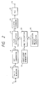
- Fig. 2 is a schematic block diagram for explaining an arrangement of a conventional encoding method using DCT conversion
- Figs. 3 to 6 are views for explaining processing of the encoding method shown in Fig. 2.
- An input terminal 2 receives a digital image signal to be encoded, which signal is obtained by raster scanning.
- the image signal input to the terminal 2 is input to an 8 x 8 blocking circuit 4, and is two-dimensionally divided into pixel blocks each consisting of (8 x 8) pixels.
- the image signal is output to the next circuit in units of pixel blocks.
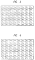
- a DCT conversion circuit 6 DCT-converts the image signal from the blocking circuit 4, and outputs an (8 x 8) data matrix for a frequency region. More specifically, a pixel block consisting of image data D 11 to D 88 , as shown in Fig. 3, is converted into a data matrix including X 11 to X 88 , as shown in Fig. 4, by the circuit 6.
- X 11 represents a DC component in the horizontal and vertical directions of the pixel block, i.e., an average value of this pixel block. If X 11 to X 88 are generally represented by X ij , a component represented by X ij has a higher frequency in the vertical direction as i is larger, and has a higher frequency in the horizontal direction as j is larger.
- the data matrix output from the DCT conversion circuit 6 is input to a linear quantization circuit 8.
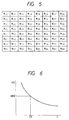
- a quantization matrix generation circuit 18 generates a quantization matrix (W 11 to W 88 ; Fig. 5) indicating weighting coefficients of quantization step sizes for DCT coefficients X 11 to X 88 , and a coefficient generation circuit 16 generates a coefficient C.
- the quantization matrix (W 11 to W 88 ), and the coefficient C are input to a multiplication circuit 20.
- the multiplication circuit 20 calculates (W ij x C), and quantization steps of the linear quantization circuit 8 are determined by outputs Q 11 to Q 88 from the multiplication circuit 20. Note that the coefficient C has a positive value, and controls the image quality and generation data amount.
- the linear quantization circuit 8 calculates X ij /Q ij , and outputs the calculation results. Assume that the outputs from the linear quantization circuit 8 are represented by G 11 to G 88 .
- the quantized conversion data G 11 to G 88 are output from a zigzag scanning circuit 10 sequentially from DC components.
- the zigzag scanning circuit 10 outputs, to a variable length coding circuit (VLC) 12, the data G 11 to G 88 in the order of G 11 , G 12 , G 21 , G 31 , G 22 , G 13 , G 14 , G 23 , G 32 , G 41 ,..., G 85 , G 86 , G 77 , G 68 , G 78 , G 87 , and G 88 .
- VLC variable length coding circuit
- the VLC 12 calculates a predicted value for, e.g., a DC component G 11 among adjacent pixel blocks, and Huffman-encodes a predicted error from the predicted value. Alternatively, the VLC 12 performs equal-length coding of only this DC component. On the other hand, the VLC encodes AC components G 12 to G 88 other than the DC component G 11 while zigzag-scanning quantization outputs from low-frequency components to high-frequency components.
- the VLC then adds an equal-length code indicating the position of a value in a group.
- variable length codes obtained in this manner can be expected to have a very high compression ratio. Assuming a compression ratio between 1/2 to 1/9 as an average, an image almost free from image quality degradation can be decoded.
- a transmission path generally has a predetermined transmission capacity per unit time.
- a code to be output has a fixed number of bits in units of frames or in units of pixel blocks.
- the above-mentioned JPEG, and the like propose a method of predicting a coefficient C0 for obtaining a desired total bit count NB0. More specifically, a given coefficient C1 is encoded, and a total bit count nb1 of the obtained code is calculated. A predicted value C2 of C0 is calculated based on nb1 and C1. This calculation can be predicted since the logarithmic curve shown in Fig. 6 passes (C1, nb1).
- an encoding amount including several % of an error from the desired total bit count NB0 can be obtained.
- processing for repetitively performing encoding to determine the value of the coefficient C0 is time-consuming, and is not suitable for an encoding apparatus, which must transmit one frame during a predetermined period of time like in transmission of motion pictures.
- an image signal having a very high bit rate such as a high-definition television signal is to be processed, such processing is impossible.
- the present invention has been made in consideration of the above situation, and has as its object to provide an image encoding apparatus for quantizing conversion data obtained by converting image information onto a frequency region, and encoding the quantized conversion data, wherein the image encoding apparatus can perform high-speed processing, and can set a data amount in units of frames to be a desired data amount.
- an image encoding apparatus comprises conversion means for converting image information into data on a frequency region, parallel output means for parallelly outputting the converted data to output the converted data of a plurality of channels, quantization means for respectively quantizing the converted data of the plurality of channels output from the parallel output means; operation means for calculating a data amount to be obtained when one of the converted data of the plurality of channels output from the quantization means is encoded, coefficient generation means for generating a quantization coefficient for controlling a quantization step of converted data of other channels of the quantization means, and encoding means for encoding at least one of the converted data of the plurality of channels output from the quantization means.
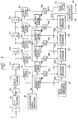
- Fig. 1 is a block diagram showing an arrangement of an encoding apparatus according to the first embodiment of the present invention wherein the present invention is applied to a transmission apparatus for transmitting a television signal.
- an input terminal 20 receives a television signal.
- the television signal input from the terminal 20 is converted into 8-bit digital data by an A/D converter 22, and is divided into (8 x 8) pixel blocks by an (8 x 8) blocking circuit 26 for performing the same operation as that in the blocking circuit shown in Fig. 2.
- the television signal is supplied to a DCT conversion circuit 28 in units of blocks.
- Pixel data D 11 to D 88 of each block are converted by the DCT conversion circuit 28 into a data matrix (X 11 to X 88 ) for a frequency region in the same manner as in Fig. 2, and the data matrix is supplied to a zigzag scanning circuit 30.
- the zigzag scanning circuit 30 performs the same operation as the zigzag scanning circuit 10 shown in Fig.
- a quantization matrix generation circuit 36 generates the above-mentioned quantization matrix (W 11 to W 88 ).
- quantization matrix data W 11 to W 88 are generated in the order corresponding to the zigzag scanning, and are supplied to multiplication circuits 38a to 38e.
- the multiplication circuit 38a receives an initial coefficient C1 as the above-mentioned coefficient (control coefficient) C from an initial coefficient generation circuit.
- the initial coefficient C1 is set to be "1".
- the quantization circuit 32a obtains quantization codes G1 11 to G1 88 based on the control coefficient C1. These quantized conversion codes G1 11 to G1 88 are input to a VLC 40a.
- VLCs 40a to 40d do not output actual encoded data, but output only pieces of total bit count information nb1 to nb4 in units of frames obtained upon execution of the same processing as in the VLC 12 in Fig. 2.
- the total bit count information nb1 output from the VLC 40a is input to a coefficient operation circuit 44a.
- Coefficient operation circuits 44a to 44d predict a control coefficient C0 corresponding to a desired total bit count NB0 using the pieces of total bit count information nb1 to nb4 from the VLCs 40a to 40d, the initial coefficient C1, and outputs C2 to C4 from the coefficient operation circuits 44a to 44c, and respectively output control coefficients C2 to C5.
- the coefficient operation circuits 44a to 44d output the control coefficients C2 to C5, obtained based on conversion data for one frame input to the quantization circuits 32a to 32d, at the input timing of conversion data for the next frame to the quantization circuits 32a to 32d.
- circuits (1FDLs) 34a to 34d delay the outputs from the zigzag scanning circuit 30 by one frame period. Therefore, the control coefficient C2 output from the coefficient operation circuit 44a is input to the multiplication circuit 38b at the input timing of conversion data for one frame, which are used for obtaining the control coefficient C2, to the quantization circuit 32b.
- the multiplication circuit 38b calculates (W ij x C), and inputs the result to the quantization circuit 32b. More specifically, the quantization circuit 32b performs the second quantization for a given frame, and obtains quantization codes G2 11 to G2 88 based on the control coefficient C2.
- the quantized conversion codes G2 11 to G2 88 are input to the VLC 40b.
- coefficient operation circuits 44b to 44d, the multiplication circuits 38c to 38e, the 1FDLs 34b to 34d, the VLCs 40b to 40d, and the quantization circuits 32c to 32e are respectively the same as those of the coefficient operation circuit 44a, the multiplication circuit 38b, the 1FDL 34a, the VLC 40a, and the quantization circuit 32b. These circuits sequentially update the predicted value of a desired control coefficient for a given frame.
- the predicted value C5 of the control coefficient obtained from the coefficient operation circuit 44d can be caused to converge to a value very close to the control coefficient C0 corresponding to the desired total bit count NB0.
- the control coefficient C5 is supplied to the multiplication circuit 38e as a final control coefficient C.
- the output from the multiplication circuit 38e is supplied to the quantization circuit 32e.
- the quantization circuit 32e quantizes the output from the 1FDL 34d, i.e., conversion data, which are delayed by a total of four frame periods, and supplies the quantized data to a VLC 40e.
- the VLC 40e actually performs encoding that was described earlier with reference to Fig. 2, and outputs encoded data (DATA).
- the encoded data are output from an entry buffer 46 at a predetermined bit rate, and are multiplexed with the final control coefficient C by a multiplexer 48.
- the multiplexed data are then output from a terminal 50 onto a transmission path.
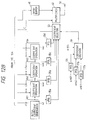
- Fig. 7 is a block diagram showing an arrangement of an encoding apparatus according to the second embodiment of the present invention wherein the present invention is applied to a transmission apparatus for transmitting a television signal.
- a coefficient operation circuit 41 supplies a predicted initial coefficient as the above-mentioned quantization coefficient (control coefficient) C1 to a multiplication circuit 38a. Note that the predicted initial coefficient will be described later.
- the coefficient operation circuit 41 predicts a control coefficient C0 corresponding to a desired total bit count NB0 using pieces of total bit count information nb1 to nb4 from VLCs 40a to 40d, the initial coefficient C1, and outputs C2 to C4 of this operation circuit 41, and outputs control coefficients C2 to C5.
- the coefficient operation circuit 41 outputs the control coefficients C2 to C5, obtained based on conversion data for one frame input to quantization circuits 32a to 32d, at the input timing of conversion data for the next frame to the quantization circuits 32a to 32d.
- the arrangement and operations of the second embodiment are the same as those of the encoding apparatus of the first embodiment, except for the above-mentioned arrangement and operations.
- a value obtained in the immediately preceding frame is used as a control coefficient to be input to the multiplication circuit 38a.
- a convergence time of the control coefficients C2 to C5 until an optimum control coefficient is obtained can be shortened, and a more accurate control coefficient can be obtained.
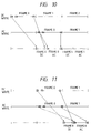
- Fig. 8A shows values C1 to C5 when a control coefficient of a given frame is obtained. As can be seen from Fig. 8A, the control coefficient converges to a target optimum control coefficient value while oscillating.
- Fig. 8B shows values C1 to C5 when a control coefficient of a frame next to the given frame is obtained.
- the initially input value C1 is the control coefficient C2 of the immediately preceding frame, i.e., the value C2 (this value will be referred to as a predicted initial coefficient) shown in Fig. 8A. It can be regarded that an optimum control coefficient of this frame is almost the same as that of the immediately preceding frame. Thus, since the value C1 becomes closer to the optimum control coefficient, the convergence time can be shortened, and a value closer to the optimum control coefficient can be obtained.
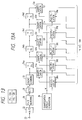
- Fig. 9 is a block diagram showing an arrangement of an encoding apparatus according to the third embodiment of the present invention wherein the present invention is applied to a transmission apparatus for transmitting a television signal.
- VLCs 40a to 40d of this embodiment calculate total data amounts of only AC components after encoding, and output pieces of total bit count information nb1 to nb4 in units of frames.
- DC components are equal-length coded.
- the operations up to a multiplication circuit 38e except for the above-mentioned processing operations of the VLCs 40a to 40d, are the same as those in the first embodiment.
- the processing operations after the multiplication circuit 38e will be described in detail below.
- the output from the multiplication circuit 38e is supplied to a quantization circuit 32e.
- the quantization circuit 32e quantizes outputs from a 1FDL 34d, i.e., at least AC components of conversion data delayed by a total of four frame periods, and supplies quantized data G5 12 to G5 88 to a VLC 40e.
- the VLC 40e actually performs encoding that was described above with reference to Fig. 2, on AC components G5 12 to G5 88 , and outputs encoded data (DATA).
- DC components are separated from the outputs from a 1FDL 34c by a DC extraction circuit 51, and are input to a quantization circuit 52.
- the quantization circuit 52 quantizes a DC component X 11 by a predetermined quantization step independently of the above-mentioned coefficient C, and inputs the quantized component to a coding circuit 54.
- the coding circuit 54 equal-length codes the above-mentioned DC component by, e.g., predicted differential encoding.
- DC component data equal-length coded by the coding circuit 54, and AC component data variable-length coded by the VLC 40e, as described above, are respectively input to buffer memories 56 and 46.
- the read operations of encoded data from the memories 46 and 56 are controlled by a buffer control circuit 58.
- control is made as follows. That is, as for encoded data for a given frame, all the DC component encoded data of the frame are read out first, and then, AC component encoded data of the same frame are read out.
- Fig. 10 is a chart showing the data write timings to the memory 46, i.e., the write timings of AC component encoded data (AC), the data write timings to memory 56, i.e., the write timings of DC component encoded data (DC), and the data read timings from these two memories.
- AC AC component encoded data
- DC DC component encoded data
- DC component encoded data (DATA-2) is quantized by the constant quantization step independently of the above-mentioned coefficient C, quantization can be performed before determination of the final coefficient C in the coefficient operation circuit 44d.
- DC component data are separated and extracted by the DC extraction circuit 51 at the input side of the 1FDL 34d at the final stage, and are quantized by the quantization circuit 52.
- DC component encoded data (DC) of the same frame already stored in the memory 56 can be read out prior to the AC component encoded data (AC).
- Fig. 11 is a chart showing the relationship between read and write timings of data corresponding to AC component encoded data (AC) and DC component encoded data (DC) when the AC and DC component data are quantized and encoded during a single frame period without using the DC extraction circuit 51.
- a memory capacity required when the transmission order of data is changed in units of frames corresponds to two frames according to the conventional arrangement.
- a memory having a capacity for one frame need only be arranged for AC component encoded data (AC) so as to change the data transmission order.
- AC AC component encoded data
- the memories 46 and 56 also have a buffer function for reading out data at a predetermined bit rate.
- the buffer control circuit 58 controls to slightly delay the data read start timing of each frame from the write start timing, so that the read addresses of data from the memory 46 do not overtake write addresses.
- AC component encoded data (AC) and the DC component encoded data (DC) read out from the memories 46 and 56, as described above, are multiplexed by a multiplexer 48 together with the final coefficient C, and the multiplexed data are output from a terminal 60 onto a transmission path at a predetermined bit rate.
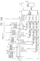
- Fig. 12 is a block diagram showing an arrangement of an encoding apparatus according to the fourth embodiment of the present invention wherein the present invention is applied to a transmission apparatus for transmitting a television signal.
- This embodiment assumes an apparatus, which does not permit that the total bit count of each frame after variable-length coding exceeds a desired total bit count NB0 even slightly.
- a predicted control coefficient is not directly used. This embodiment selects, from control coefficients for a given frame, a control coefficient corresponding to a total bit count after variable-length coding, which is less than and closest to the desired total bit count NB0.
- a four-frame period delay circuit (4FDL) 55a, a three-frame period delay circuit (3FDL) 55b, a two-frame period delay circuit (2FDL) 55c, and a one-frame period delay circuit (1FDL) 55d respectively delay control coefficients C1, C2, C3, and C4.
- the control coefficients C1, C2, C3, and C4 input to a coefficient selector 53 become those for an image of a single frame.
- These coefficients C1 to C4 are input to the coefficient selector 53 at the input timing of an image of the corresponding frame to a quantization circuit 32e through a 1FDL 34d.
- the timings of pieces of total bit count information nb1 to nb4 obtained when quantization and encoding are performed using these control coefficients C1 to C4 are adjusted to each other by a 3FDL 57a, a 2FDL 57b, and a 1FDL 57c. More specifically, the pieces of total bit count (data mount) information nb1 to nb4 corresponding to the control coefficients C1 to C4 input to the coefficient selector 53 are input to a coefficient decision circuit 59 immediately before a period for which these control coefficients C1 to C4 are input to the coefficient selector 53.
- the coefficient decision circuit 59 detects information corresponding to a total bit count, which is less than and closest to the desired total bit count NB0, and supplies 2-bit control information to the coefficient selector 53 according to the detection result.
- the coefficient selector 53 selects a control coefficient corresponding to a total bit count, which is less than and closest to the desired total bit count NB0 upon variable-length coding, from the control coefficients C1 to C4, and outputs the selected coefficient.
- control coefficient output from the coefficient selector 53 is determined as a final control coefficient C, and is supplied to a multiplication circuit 38e.
- the output from the multiplication circuit 38e is supplied to the quantization circuit 32e.
- the quantization circuit 32e quantizes outputs from the 1FDL 34d, i.e., conversion data delayed by a total of four frame periods, and supplies the quantized data to a VLC 40e.
- the VLC 40e actually performs encoding that was described above with reference to Fig. 2, and outputs encoded data (DATA).
- the encoded data are output from an entry buffer 46 at a predetermined bit rate, and are multiplexed with the final control coefficient C by a multiplexer 48.
- the multiplexed data are then output from a terminal 50 onto a transmission path.
- Fig. 13 is a block diagram showing an arrangement of an encoding apparatus according to the fifth embodiment of the present invention wherein the present invention is applied to a transmission apparatus for transmitting a television signal.
- This embodiment assumes an apparatus, which does not permit that the total bit count of each frame after variable-length coding exceeds a desired total bit count NB0 even slightly, like in the above-mentioned fourth embodiment.
- VLCs 40a to 40d of this embodiment output pieces of total bit count information in units of frames, and actually encoded codes.
- Pieces of total bit count information nb1 to nb5 calculated by the VLCs 40a to 40e are input to a rate fixer 43.
- the rate fixer 43 discriminates, from nb1 to nb5 for a single frame, total bit count information corresponding to a total bit count, which is equal to or smaller than and closest to NB0, and determines a control coefficient giving the total bit count and encoded codes as a final control coefficient and encoded codes.
- Data buffers 45a to 45j are used for supplying encoded codes d1 to d4, output from the VLCs 40a to 40d for the same frame as a frame corresponding to an encoded code d5 output from a VLC 40e, to a data selection switch 47 at the same timing as the encoded code d5.
- the data buffers 45a to 45j delay (buffer) control coefficients C1 to C4 giving the four encoded codes d1 to d4 for a single frame, so that these control coefficients are supplied to the data selection switch at the same timing as the encoded codes d1 to d4.
- the rate fixer 43 controls the data selection switch 47 to output one of the encoded code d5 output from the VLC 40e, and the encoded codes d1, d2, d3, and d4 output from the data buffers 45d, 45g, 45i, and 45j as a final encoded code DATA.
- the data selection switch 47 outputs one of the control coefficient C5 output from a coefficient operation circuit 44d, and the control coefficients C1, C2, C3, and C4 output from the data buffers 45d, 45g, 45i, and 45j as a final control coefficient F.
- the encoded code DATA and the control coefficient F are multiplexed by a multiplexer 48, and are output from a terminal 50 onto a transmission path.
- the data transmission order can be changed, i.e., DC component encoded data (DC) can be output prior to AC component data using a small memory capacity.
- DC DC component encoded data
- control coefficient F is determined in units of frames. However, if there is a margin for a processing time, a unit (period) for determining the value of the control coefficient F can be decreased (shortened).
- the coefficient operation circuits 44b to 44d predict the desired control coefficient C0 using the coefficients C2 to C4 output from the coefficient operation circuits 44a to 44c, and the pieces of total bit count information nb2 to nb4 obtained when quantization and variable-length coding are performed according to the coefficients C2 to C4.
- These circuits can more accurately predict the control coefficient using coefficients and total bit count information at the immediately preceding stages in addition to the above-mentioned coefficients and information. For example, if the coefficient operation circuit 44b uses the coefficients C1 and C2 and the pieces of total bit count information nb1 and nb2 so as to calculate the coefficient C3, the coefficient C0 can be predicted more accurately.
- the 1FDLs 34a to 34d are series-connected at the output side of the DCT conversion circuit 28 and the zigzag scanning circuit 30.
- a plurality of 1FDLs may be connected in series at the output side of the (8 x 8) blocking circuit 26 so as to save the memory capacity of the 1FDLs, and the outputs of the 1FDLs may be connected to the DCT conversion circuit and the zigzag scanning circuit.
- the encoded code output from the VLCs 40a to 40e for a single frame can be output.
- the same effect can be obtained in such a manner that the encoded codes from only the VLCs 40d and 40d can be output, or the encoded codes output from the VLCs 40c to 40e can be selectively output.
- the capacity of each data buffer can be decreased as compared to the embodiment shown in Fig. 13, and an increase in hardware size can be suppressed.
Landscapes
- Engineering & Computer Science (AREA)
- Multimedia (AREA)
- Signal Processing (AREA)
- Computing Systems (AREA)
- Theoretical Computer Science (AREA)
- Compression Or Coding Systems Of Tv Signals (AREA)
- Compression, Expansion, Code Conversion, And Decoders (AREA)
Applications Claiming Priority (16)
| Application Number | Priority Date | Filing Date | Title |
|---|---|---|---|
| JP1646691 | 1991-02-07 | ||
| JP16466/91 | 1991-02-07 | ||
| JP03016466A JP3135271B2 (ja) | 1991-02-07 | 1991-02-07 | 符号化装置 |
| JP113189/91 | 1991-05-17 | ||
| JP113226/91 | 1991-05-17 | ||
| JP3113226A JPH04341065A (ja) | 1991-05-17 | 1991-05-17 | 画像符号化装置及びその方法 |
| JP11322691 | 1991-05-17 | ||
| JP11318991A JP3227170B2 (ja) | 1991-05-17 | 1991-05-17 | 画像符号化装置 |
| JP11318991 | 1991-05-17 | ||
| JP28495791A JP3387516B2 (ja) | 1991-10-30 | 1991-10-30 | 画像符号化装置及びその方法 |
| JP28495691 | 1991-10-30 | ||
| JP284956/91 | 1991-10-30 | ||
| JP28495691A JPH05122530A (ja) | 1991-10-30 | 1991-10-30 | 画像符号化装置 |
| JP28495791 | 1991-10-30 | ||
| JP284957/91 | 1991-10-30 | ||
| EP92300851A EP0498578B1 (fr) | 1991-02-07 | 1992-01-31 | Dispositif de codage d'images |
Related Parent Applications (2)
| Application Number | Title | Priority Date | Filing Date |
|---|---|---|---|
| EP92300851.0 Division | 1992-01-31 | ||
| EP92300851A Division EP0498578B1 (fr) | 1991-02-07 | 1992-01-31 | Dispositif de codage d'images |
Publications (3)
| Publication Number | Publication Date |
|---|---|
| EP0804036A2 true EP0804036A2 (fr) | 1997-10-29 |
| EP0804036A3 EP0804036A3 (fr) | 1998-01-21 |
| EP0804036B1 EP0804036B1 (fr) | 2000-09-06 |
Family
ID=27519817
Family Applications (3)
| Application Number | Title | Priority Date | Filing Date |
|---|---|---|---|
| EP98201257A Expired - Lifetime EP0863672B1 (fr) | 1991-02-07 | 1992-01-31 | Appareil de codage d'image |
| EP97201674A Expired - Lifetime EP0804036B1 (fr) | 1991-02-07 | 1992-01-31 | Dispositif de codage d'images |
| EP92300851A Expired - Lifetime EP0498578B1 (fr) | 1991-02-07 | 1992-01-31 | Dispositif de codage d'images |
Family Applications Before (1)
| Application Number | Title | Priority Date | Filing Date |
|---|---|---|---|
| EP98201257A Expired - Lifetime EP0863672B1 (fr) | 1991-02-07 | 1992-01-31 | Appareil de codage d'image |
Family Applications After (1)
| Application Number | Title | Priority Date | Filing Date |
|---|---|---|---|
| EP92300851A Expired - Lifetime EP0498578B1 (fr) | 1991-02-07 | 1992-01-31 | Dispositif de codage d'images |
Country Status (4)
| Country | Link |
|---|---|
| US (4) | US5251029A (fr) |
| EP (3) | EP0863672B1 (fr) |
| DE (3) | DE69232123T2 (fr) |
| SG (4) | SG94708A1 (fr) |
Families Citing this family (30)
| Publication number | Priority date | Publication date | Assignee | Title |
|---|---|---|---|---|
| US5416854A (en) * | 1990-07-31 | 1995-05-16 | Fujitsu Limited | Image data processing method and apparatus |
| US5657399A (en) * | 1991-05-17 | 1997-08-12 | Canon Kabushiki Kaisha | Encoding/decoding apparatus using quantizing steps information |
| US5349384A (en) * | 1992-01-14 | 1994-09-20 | Sony Corporation | Apparatus and methods for transmitting compressed digital image signals |
| JP3166291B2 (ja) * | 1992-04-03 | 2001-05-14 | ソニー株式会社 | 量子化コントロール回路 |
| US5291281A (en) * | 1992-06-18 | 1994-03-01 | General Instrument Corporation | Adaptive coding level control for video compression systems |
| EP1006731B1 (fr) * | 1993-03-29 | 2007-06-13 | Canon Kabushiki Kaisha | Méthode de contrôle de la quantité de données et codeur la mettant en oeuvre |
| US5469208A (en) * | 1993-05-26 | 1995-11-21 | Intel Corporation | Dequantization using decrements and multiply |
| JPH07123269A (ja) * | 1993-10-22 | 1995-05-12 | Fuji Xerox Co Ltd | 画像信号の符号化装置 |
| JP2626521B2 (ja) * | 1993-11-29 | 1997-07-02 | 日本電気株式会社 | 画像符号変換装置 |
| BE1007807A3 (nl) * | 1993-11-30 | 1995-10-24 | Philips Electronics Nv | Inrichting voor het coderen van een videosignaal. |
| BE1007808A3 (nl) * | 1993-11-30 | 1995-10-24 | Philips Electronics Nv | Inrichting voor het coderen van een videosignaal. |
| EP0660619A1 (fr) * | 1993-12-22 | 1995-06-28 | Laboratoires D'electronique Philips S.A.S. | Procédé de codage d'images à longueur variable et dispositif de mise en oeuvre d'un tel procédé |
| US5754235A (en) * | 1994-03-25 | 1998-05-19 | Sanyo Electric Co., Ltd. | Bit-rate conversion circuit for a compressed motion video bitstream |
| JPH07298272A (ja) | 1994-04-28 | 1995-11-10 | Canon Inc | 映像符号化装置 |
| JP3115199B2 (ja) * | 1994-12-16 | 2000-12-04 | 松下電器産業株式会社 | 画像圧縮符号化装置 |
| US5825970A (en) * | 1994-12-20 | 1998-10-20 | Lg Electronics Inc. | Quantization number selecting apparatus for DVCR and method therefor |
| JPH08181987A (ja) * | 1994-12-22 | 1996-07-12 | Canon Inc | 符号化装置 |
| JPH09512410A (ja) * | 1995-02-15 | 1997-12-09 | フィリップス エレクトロニクス ネムローゼ フェンノートシャップ | ビデオ信号の符号変換方法および装置 |
| US5872599A (en) * | 1995-03-08 | 1999-02-16 | Lucent Technologies Inc. | Method and apparatus for selectively discarding data when required in order to achieve a desired Huffman coding rate |
| FI981546A7 (fi) * | 1998-07-03 | 2000-01-04 | Nokia Corp | Tiedonsiirtomenetelmä ja matkapuhelinjärjestelmä |
| JP2003520512A (ja) * | 2000-01-14 | 2003-07-02 | コーニンクレッカ フィリップス エレクトロニクス エヌ ヴィ | 伝送符号化方法及び伝送符号化装置 |
| JP2001285645A (ja) | 2000-01-25 | 2001-10-12 | Canon Inc | 画像入力装置、画像処理装置、画像入力方法、画像処理方法、及び画像入力システム |
| JP4109404B2 (ja) * | 2000-04-26 | 2008-07-02 | 松下電器産業株式会社 | 符号化装置および符号化方法 |
| JP4569840B2 (ja) * | 2007-09-12 | 2010-10-27 | ソニー株式会社 | 画像符号化装置、画像符号化方法 |
| CN101779468B (zh) * | 2008-06-27 | 2012-07-04 | 索尼公司 | 图像处理装置和图像处理方法 |
| US8374451B2 (en) * | 2008-06-27 | 2013-02-12 | Sony Corporation | Image processing device and image processing method for reducing the circuit scale |
| JP2015008387A (ja) | 2013-06-25 | 2015-01-15 | キヤノン株式会社 | 画像処理装置、画像処理方法およびプログラム並びに撮像装置 |
| CN107389211B (zh) * | 2017-06-29 | 2019-03-12 | 西安邮电大学 | 一种二进制码转温度计码电路 |
| JP7193929B2 (ja) | 2018-05-15 | 2022-12-21 | キヤノン株式会社 | 画像処理装置、画像処理方法、及び、プログラム |
| GB2578633B (en) * | 2018-11-02 | 2021-10-13 | Advanced Risc Mach Ltd | Encoding data arrays |
Family Cites Families (11)
| Publication number | Priority date | Publication date | Assignee | Title |
|---|---|---|---|---|
| US4541012A (en) * | 1982-01-04 | 1985-09-10 | Compression Labs, Inc. | Video bandwidth reduction system employing interframe block differencing and transform domain coding |
| JPS62222783A (ja) * | 1986-03-24 | 1987-09-30 | Kokusai Denshin Denwa Co Ltd <Kdd> | 動画像の高能率符号化方式 |
| US4920426A (en) * | 1986-11-10 | 1990-04-24 | Kokusai Denshin Denwa Co., Ltd. | Image coding system coding digital image signals by forming a histogram of a coefficient signal sequence to estimate an amount of information |
| EP0339589A3 (fr) * | 1988-04-28 | 1992-01-02 | Sharp Kabushiki Kaisha | Système de codage par transformation orthogonale pour données d'images |
| US4984076A (en) * | 1988-07-27 | 1991-01-08 | Kabushiki Kaisha Toshiba | Image compression coding system |
| US5073821A (en) * | 1989-01-30 | 1991-12-17 | Matsushita Electric Industrial Co., Ltd. | Orthogonal transform coding apparatus for reducing the amount of coded signals to be processed and transmitted |
| US5128758A (en) * | 1989-06-02 | 1992-07-07 | North American Philips Corporation | Method and apparatus for digitally processing a high definition television augmentation signal |
| EP0401854B1 (fr) * | 1989-06-09 | 1997-08-06 | Matsushita Electric Industrial Co., Ltd. | Dispositif pour codage par transformation orthogonale |
| JP3085465B2 (ja) * | 1989-10-31 | 2000-09-11 | オリンパス光学工業株式会社 | 画像データの符号化装置および符号化方法 |
| US5146324A (en) * | 1990-07-31 | 1992-09-08 | Ampex Corporation | Data compression using a feedforward quantization estimator |
| EP0475251B1 (fr) * | 1990-09-10 | 1997-03-26 | Mitsubishi Denki Kabushiki Kaisha | Dispositif de codage pour des données d'image numériques |
-
1992
- 1992-01-31 SG SG9802913A patent/SG94708A1/en unknown
- 1992-01-31 DE DE69232123T patent/DE69232123T2/de not_active Expired - Fee Related
- 1992-01-31 DE DE69231426T patent/DE69231426T2/de not_active Expired - Lifetime
- 1992-01-31 DE DE69228841T patent/DE69228841T2/de not_active Expired - Lifetime
- 1992-01-31 EP EP98201257A patent/EP0863672B1/fr not_active Expired - Lifetime
- 1992-01-31 SG SG9802904A patent/SG95586A1/en unknown
- 1992-01-31 EP EP97201674A patent/EP0804036B1/fr not_active Expired - Lifetime
- 1992-01-31 EP EP92300851A patent/EP0498578B1/fr not_active Expired - Lifetime
- 1992-01-31 SG SG1996006638A patent/SG43261A1/en unknown
- 1992-01-31 SG SG9802915A patent/SG94709A1/en unknown
- 1992-02-03 US US07/829,404 patent/US5251029A/en not_active Expired - Lifetime
-
1993
- 1993-03-17 US US08/032,633 patent/US5333013A/en not_active Expired - Lifetime
-
1994
- 1994-05-04 US US08/237,891 patent/US5452007A/en not_active Expired - Lifetime
- 1994-11-08 US US08/337,442 patent/US5528298A/en not_active Expired - Lifetime
Also Published As
| Publication number | Publication date |
|---|---|
| DE69232123D1 (de) | 2001-11-15 |
| US5528298A (en) | 1996-06-18 |
| DE69231426D1 (de) | 2000-10-12 |
| EP0804036A3 (fr) | 1998-01-21 |
| EP0863672A3 (fr) | 1998-11-25 |
| EP0498578B1 (fr) | 1999-04-07 |
| EP0804036B1 (fr) | 2000-09-06 |
| US5333013A (en) | 1994-07-26 |
| EP0863672B1 (fr) | 2001-10-10 |
| SG94708A1 (en) | 2003-03-18 |
| SG94709A1 (en) | 2003-03-18 |
| DE69228841D1 (de) | 1999-05-12 |
| US5251029A (en) | 1993-10-05 |
| DE69232123T2 (de) | 2002-05-02 |
| DE69228841T2 (de) | 1999-09-16 |
| US5452007A (en) | 1995-09-19 |
| SG43261A1 (en) | 1997-10-17 |
| EP0863672A2 (fr) | 1998-09-09 |
| EP0498578A2 (fr) | 1992-08-12 |
| SG95586A1 (en) | 2003-04-23 |
| DE69231426T2 (de) | 2001-02-22 |
| EP0498578A3 (en) | 1993-09-15 |
Similar Documents
| Publication | Publication Date | Title |
|---|---|---|
| US5251029A (en) | Image encoding apparatus | |
| JP3109854B2 (ja) | 画像符号化方法及び装置 | |
| US5337049A (en) | Efficient coding signal processor | |
| EP0526201B1 (fr) | Appareil et méthode de transmission de signal vidéo | |
| US5835149A (en) | Bit allocation in a coded video sequence | |
| KR100610520B1 (ko) | 비디오 데이터 부호화 장치, 비디오 데이터 부호화 방법, 비디오데이터 전송 장치 및 비디오 데이터 기록 매체 | |
| JP2504880B2 (ja) | チャンネル帯域幅の割当装置及び割当方法 | |
| EP1012778B1 (fr) | Procede et systeme de regulation de debit basee sur des macroblocs dans un systeme de codage | |
| US5283646A (en) | Quantizer control method and apparatus | |
| EP0562787B1 (fr) | Méthode et dispositif de codage d'image | |
| US5892548A (en) | Adaptive quantizer with modification of high frequency coefficients | |
| JP2000013799A (ja) | 動き補償符号化復号化装置及びその方法 | |
| JPH1093966A (ja) | 画像符号化装置 | |
| US5907362A (en) | Picture coding apparatus | |
| US5644660A (en) | Method and apparatus for efficiently transmitting forced updates in a moving picture codec | |
| US5905578A (en) | Coding apparatus | |
| EP0803163A1 (fr) | Systeme multiplexeur mettant en uvre des codeurs a debit binaire constant | |
| EP0857393A1 (fr) | Dispositif et procede pour la selection d'un mode de codage dans un systeme de codage a base de blocs | |
| JP2793402B2 (ja) | 画像符号化装置 | |
| EP0761048A1 (fr) | Systeme d'attribution dynamique d'une ressource disponible en faible quantite | |
| EP0756789B1 (fr) | Appareil de determination de complexite | |
| WO1999043161A1 (fr) | Identification des differences visuellement perceptibles entre deux images | |
| JP3387516B2 (ja) | 画像符号化装置及びその方法 | |
| JP3397682B2 (ja) | 画像符号化装置 | |
| JP3135271B2 (ja) | 符号化装置 |
Legal Events
| Date | Code | Title | Description |
|---|---|---|---|
| PUAI | Public reference made under article 153(3) epc to a published international application that has entered the european phase |
Free format text: ORIGINAL CODE: 0009012 |
|
| AC | Divisional application: reference to earlier application |
Ref document number: 498578 Country of ref document: EP |
|
| AK | Designated contracting states |
Kind code of ref document: A2 Designated state(s): DE ES FR GB IT NL |
|
| PUAL | Search report despatched |
Free format text: ORIGINAL CODE: 0009013 |
|
| AK | Designated contracting states |
Kind code of ref document: A3 Designated state(s): DE ES FR GB IT NL |
|
| 17P | Request for examination filed |
Effective date: 19980612 |
|
| 17Q | First examination report despatched |
Effective date: 19980811 |
|
| GRAG | Despatch of communication of intention to grant |
Free format text: ORIGINAL CODE: EPIDOS AGRA |
|
| 17Q | First examination report despatched |
Effective date: 19980811 |
|
| GRAG | Despatch of communication of intention to grant |
Free format text: ORIGINAL CODE: EPIDOS AGRA |
|
| GRAH | Despatch of communication of intention to grant a patent |
Free format text: ORIGINAL CODE: EPIDOS IGRA |
|
| GRAH | Despatch of communication of intention to grant a patent |
Free format text: ORIGINAL CODE: EPIDOS IGRA |
|
| GRAA | (expected) grant |
Free format text: ORIGINAL CODE: 0009210 |
|
| AC | Divisional application: reference to earlier application |
Ref document number: 498578 Country of ref document: EP |
|
| AK | Designated contracting states |
Kind code of ref document: B1 Designated state(s): DE ES FR GB IT NL |
|
| PG25 | Lapsed in a contracting state [announced via postgrant information from national office to epo] |
Ref country code: IT Free format text: LAPSE BECAUSE OF FAILURE TO SUBMIT A TRANSLATION OF THE DESCRIPTION OR TO PAY THE FEE WITHIN THE PRE;WARNING: LAPSES OF ITALIAN PATENTS WITH EFFECTIVE DATE BEFORE 2007 MAY HAVE OCCURRED AT ANY TIME BEFORE 2007. THE CORRECT EFFECTIVE DATE MAY BE DIFFERENT FROM THE ONE RECORDED.SCRIBED TIME-LIMIT Effective date: 20000906 Ref country code: ES Free format text: THE PATENT HAS BEEN ANNULLED BY A DECISION OF A NATIONAL AUTHORITY Effective date: 20000906 |
|
| REF | Corresponds to: |
Ref document number: 69231426 Country of ref document: DE Date of ref document: 20001012 |
|
| ET | Fr: translation filed | ||
| PLBE | No opposition filed within time limit |
Free format text: ORIGINAL CODE: 0009261 |
|
| STAA | Information on the status of an ep patent application or granted ep patent |
Free format text: STATUS: NO OPPOSITION FILED WITHIN TIME LIMIT |
|
| 26N | No opposition filed | ||
| REG | Reference to a national code |
Ref country code: GB Ref legal event code: IF02 |
|
| PGFP | Annual fee paid to national office [announced via postgrant information from national office to epo] |
Ref country code: FR Payment date: 20100210 Year of fee payment: 19 |
|
| PGFP | Annual fee paid to national office [announced via postgrant information from national office to epo] |
Ref country code: GB Payment date: 20100126 Year of fee payment: 19 Ref country code: DE Payment date: 20100131 Year of fee payment: 19 |
|
| PGFP | Annual fee paid to national office [announced via postgrant information from national office to epo] |
Ref country code: NL Payment date: 20100118 Year of fee payment: 19 |
|
| REG | Reference to a national code |
Ref country code: NL Ref legal event code: V1 Effective date: 20110801 |
|
| GBPC | Gb: european patent ceased through non-payment of renewal fee |
Effective date: 20110131 |
|
| REG | Reference to a national code |
Ref country code: FR Ref legal event code: ST Effective date: 20110930 |
|
| PG25 | Lapsed in a contracting state [announced via postgrant information from national office to epo] |
Ref country code: FR Free format text: LAPSE BECAUSE OF NON-PAYMENT OF DUE FEES Effective date: 20110131 |
|
| PG25 | Lapsed in a contracting state [announced via postgrant information from national office to epo] |
Ref country code: GB Free format text: LAPSE BECAUSE OF NON-PAYMENT OF DUE FEES Effective date: 20110131 |
|
| PG25 | Lapsed in a contracting state [announced via postgrant information from national office to epo] |
Ref country code: NL Free format text: LAPSE BECAUSE OF NON-PAYMENT OF DUE FEES Effective date: 20110801 |
|
| REG | Reference to a national code |
Ref country code: DE Ref legal event code: R119 Ref document number: 69231426 Country of ref document: DE Effective date: 20110802 |
|
| PG25 | Lapsed in a contracting state [announced via postgrant information from national office to epo] |
Ref country code: DE Free format text: LAPSE BECAUSE OF NON-PAYMENT OF DUE FEES Effective date: 20110802 |