EP0803751B1 - Endhülse für einen Glasfaserstecker - Google Patents
Endhülse für einen Glasfaserstecker Download PDFInfo
- Publication number
- EP0803751B1 EP0803751B1 EP97302726A EP97302726A EP0803751B1 EP 0803751 B1 EP0803751 B1 EP 0803751B1 EP 97302726 A EP97302726 A EP 97302726A EP 97302726 A EP97302726 A EP 97302726A EP 0803751 B1 EP0803751 B1 EP 0803751B1
- Authority
- EP
- European Patent Office
- Prior art keywords
- ferrule
- small
- hole
- diameter hole
- diameter portion
- Prior art date
- Legal status (The legal status is an assumption and is not a legal conclusion. Google has not performed a legal analysis and makes no representation as to the accuracy of the status listed.)
- Expired - Lifetime
Links
- 230000003287 optical effect Effects 0.000 title claims description 29
- 239000013307 optical fiber Substances 0.000 claims description 40
- 230000003139 buffering effect Effects 0.000 claims description 25
- 239000000853 adhesive Substances 0.000 description 14
- 230000001070 adhesive effect Effects 0.000 description 14
- 239000000835 fiber Substances 0.000 description 6
- 230000000694 effects Effects 0.000 description 3
- 238000000034 method Methods 0.000 description 2
- 230000002093 peripheral effect Effects 0.000 description 2
- 230000015572 biosynthetic process Effects 0.000 description 1
- 239000000919 ceramic Substances 0.000 description 1
- 230000002542 deteriorative effect Effects 0.000 description 1
- 239000011521 glass Substances 0.000 description 1
- 239000000463 material Substances 0.000 description 1
- 239000002184 metal Substances 0.000 description 1
- 238000012986 modification Methods 0.000 description 1
- 230000004048 modification Effects 0.000 description 1
- 238000000465 moulding Methods 0.000 description 1
- 239000004033 plastic Substances 0.000 description 1
- 238000005498 polishing Methods 0.000 description 1
- 230000002035 prolonged effect Effects 0.000 description 1
- 238000004904 shortening Methods 0.000 description 1
- 230000003746 surface roughness Effects 0.000 description 1
Images


Classifications
-
- G—PHYSICS
- G02—OPTICS
- G02B—OPTICAL ELEMENTS, SYSTEMS OR APPARATUS
- G02B6/00—Light guides; Structural details of arrangements comprising light guides and other optical elements, e.g. couplings
- G02B6/24—Coupling light guides
- G02B6/36—Mechanical coupling means
- G02B6/38—Mechanical coupling means having fibre to fibre mating means
- G02B6/3807—Dismountable connectors, i.e. comprising plugs
- G02B6/3833—Details of mounting fibres in ferrules; Assembly methods; Manufacture
- G02B6/3834—Means for centering or aligning the light guide within the ferrule
- G02B6/3835—Means for centering or aligning the light guide within the ferrule using discs, bushings or the like
-
- G—PHYSICS
- G02—OPTICS
- G02B—OPTICAL ELEMENTS, SYSTEMS OR APPARATUS
- G02B6/00—Light guides; Structural details of arrangements comprising light guides and other optical elements, e.g. couplings
- G02B6/24—Coupling light guides
- G02B6/36—Mechanical coupling means
- G02B6/38—Mechanical coupling means having fibre to fibre mating means
- G02B6/3807—Dismountable connectors, i.e. comprising plugs
- G02B6/3833—Details of mounting fibres in ferrules; Assembly methods; Manufacture
- G02B6/3855—Details of mounting fibres in ferrules; Assembly methods; Manufacture characterised by the method of anchoring or fixing the fibre within the ferrule
Definitions
- This invention relates to a ferrule for optical connectors.
- the ferrule for optical connectors is used to connect optical fibres directly with each other.
- a conventional ferrule contains an optical fibre inserting hole 101 formed through a ferrule body 100 in its axial direction and an optical fibre inserted into the optical fibre inserting hole 101 is fixed therein by an adhesive.
- An excessive portion of the optical fibre protruding from each end of the ferrule body 100 is cut off and the cut portion thereof is finished to a mirror state so as to be used as a connecting end.
- this connecting end By bringing this connecting end into contact with that of other ferrule body constructed in the same manner, the optical fibres are directly connected with each other.
- the optical fibres are directly connected with each other through the ferrule as described above, the optical fibre must be firmly fixed to the interior of the optical fibre inserting hole 101 in the ferrule with an adhesive so as to have a predetermined fixing strength.
- this fixing strength is closely related to a length L of the optical fibre inserting hole 101 and the longer the length, the larger the fixing strength of the optical fibre in the optical fibre inserting hole 101 is.
- that length L is often selected to be about 10mm.
- the length of the optical fibre inserting hole 101 is prolonged like this, the following difficulties may occur in processing of the optical fibre. That is, the linearity of the optical fibre inserting hole 101 cannot be easily obtained. Further, hole processing for making the optical fibre inserting hole 101 becomes difficult and it takes very long to process the internal surface of the optical fibre inserting hole 101. So that, a funnel type optical connector ferrule as shown in FIG. 8 has been proposed.
- This optical fibre inserting hole is constructed so as to have two steps, a large-diameter hole 102 and a small-diameter hole 103. By holding an optical buffered fibre by the large-diameter hole 102, the length LN at the small-diameter hole 103 for fixing the optical fibre is shortened.
- the tunnel type ferrule can solve the problem of a difficulty in processing by shortening the length LN of the small-diameter hole 103 in which the optical fibre is to be fixed, a sufficient fibre fixing strength cannot be obtained easily and further a deviation in axis between the large-diameter hole 102 and the small-diameter hole 103 may occur. This often reduces the connecting performance of the optical fibre.
- this type of ferrule is processed by centring in which the external diameter thereof is finished to a predetermined size with a small-diameter hole of the ferrule as a centre of this processing.
- both ends of the funnel type ferrule are supported by two conical-shaped centres and then the ferrule is rotated to grind the outer peripheral surface thereof.
- shape accuracy e.g., circularity
- an object of the present invention is to provide a ferrule for optical connectors which has been improved to solve the above described problem of the funnel type optical connector ferrule.
- the invention provides a ferrule for optical connectors as defined in claim 1.
- the diameter of the large-diameter hole may be of an appropriate size to allow the optical buffered fibre to pass therethrough.
- the adhesive goes in between the optical fibre and the small-diameter hole; and at the same time, the adhesive goes in between the optical fibre and the buffering hole.
- the optical fibre is fixed in the ferrule firmly by the adhesive. Because a required fixing strength between the optical fibre and the ferrule mostly depends on this bonding, the length of the small-diameter hole may be short.
- the internal surface of the small-diameter hole determines the accuracy of an optical fibre fixing position in the ferrule and so it is sufficient to finish only the internal surface of the small-diameter hole which may be relatively short, to a predetermined size, this leads to a reduction of processing time for the ferrule.
- a ferrule for optical connectors wherein the internal surface of the large-diameter hole has three lines of protrusions extending along the axial direction thereof. These lines of protrusions are preferred to be provided at intervals of 120°.
- the height of the protrusions should be determined to be an appropriate one in which a circle passing through respective vertexes of three protrusions at an external end of the large-diameter hole does not interfere with the internal surface of the large-diameter hole.
- This structure enables an accurate centring by a conical-shaped centre applied thereto for the following reason when the outer diameter of the ferrule is ground with respect to the centre of the diameter hole to a predetermined size.
- the inner peripheral surface of the small-diameter hole is substantially circular by polishing.
- a conical-shaped centre applied to the outer side end of the large-diameter hole is supported by three protrusions provided thereon such that it is stably supported by three points.
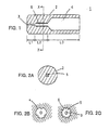
- FIG. 1 is a longitudinal sectional view of a first embodiment of the optical connector ferrule according to the present invention.
- a ferrule 1 for optical connectors has a cylindrical ferrule body 2 having a through-hole for fixing an optical fibre.
- the through-hole comprises a small-diameter hole 3 and a large-diameter hole 4 having a larger diameter than the small-diameter hole 3.
- a buffering hole 5 is provided between the small-diameter hole 3 and the large-diameter hole 4.
- the diameter of the small-diameter hole 3 is determined to be slightly larger than the outer diameter of an optical fibre so that the optical fibre is inserted into it and positioned thereby.
- the small-diameter hole 3 is formed so as to have the same cross section throughout the entire length L1, as shown in Fig. 1.
- the internal surface of the small-diameter hole 3 is polished so as to have a predetermined level of surface roughness.
- the large-diameter hole 4 is formed so as to have a slightly larger diameter than the external diameter of the optical buffered fibre allowing the optical buttered fibre to pass through and have a length of L3, as shown in Fig. 1. It has substantially the same cross section throughout the entire length thereof.
- a buffering hole 5 is formed so as to have a diameter which is larger than the internal diameter of the small-diameter hole 3 and smaller than the internal diameter of the large-diameter hole 4.
- the buffering hole 5 has substantially the same cross section throughout the entire length of L2, as shown in Fig. 1.
- FIG. 2A grooves 6 of concave and convex pattern are formed on the internal wall of the buttering hole 5 so as to form space for holding an adhesive between the optical fibre to be inserted into the buffering hole 5 and the walls of the buffering hole 5.
- This space may be formed appropriately so as to define a volume sufficient for holding a sufficient amount of adhesive for fixing the optical fibre to the ferrule 2 with a predetermined fixing strength.
- the ferrule body 2 may be made of any known material such as ceramic, plastic, glass and metal.
- FIG. 2B shows an enlarged view of the buffering hole 5 in FIG. 2A in the first embodiment
- FIG. 2C shows an enlarged view of a portion in the vicinity of the buttering hole 5 according to a second embodiment.
- the adhesive goes in between the optical fibre and the small-diameter hole 3 and also between the optical fibre and the buffering hole 5.
- adhesive of an amount sufficient for fixing the optical fibre on the internal wall of the buffering hole 5 goes in therebetween.
- This portion provides most of a fixing strength required between the optical fibre and the ferrule 2 and therefore the length L1 of the small-diameter hole 3 may be short.
- the internal surface of the small-diameter hole 3 determines an accuracy of the optical fibre fixing position in the ferrule 2.
- FIG. 3 is a longitudinal sectional view of a third embodiment of the optical connector ferrule according to an invention claimed in claim 2.
- FIG. 4 is a sectional view taken along the line Y-Y indicating a portion to the left therefrom in FIG. 3.
- a ferrule 11 for optical connector shown in Fig. 3 is basically the same as ferrule 1 shown in FIG. 1, the same reference numerals are attached to parts corresponding to each part of FIG. 1 and a description thereof is omitted.
- the ferrule 11 shown in FIG. 3 is different from the ferrule 1 shown in FIG. 1 in that three lines of protrusions 4A, 4B, 4C are formed axially on the internal wall of the large-diameter hole 4.
- the protrusions 4A, 4B, 4C are formed with rectangular sections and at each interval of 120°C on the internal wall of the large-diameter hole 4.
- the ferrule 11 shown in FIG. 3 provides the following effect in addition to an effect provided by the ferrule 1 shown in FIG. 1. That is, when the external surface of the ferrule 2 is ground with respect to the centre of the small-diameter hole 3 to a predetermined size, because the internal surface of the small-diameter hole 3 is in a substantially circular state due to grinding, accurate centring can be conducted by a conical centre (not shown) applied thereto. On the other hand, a conical centre (not shown) applied to an external end 41 of the large-diameter hole 4 is supported at three protrusions 4A to 4C provided thereon such that it is stably supported by three points.
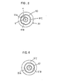
- FIG. 5 is a longitudinal sectional view of a fourth embodiment of the optical connector ferrule. With respect to parts shown in FIG. 5, the same reference numerals are used to designate parts corresponding to FIG. 1 and a description thereof is omitted.
- a ferrule 20 shown in FIG. 5 has three protruded sections 51A, 51B, 51C each having a rectangular cross section and a small protrusion group 60 formed in configuration of a plurality of concave and convex portions.
- the three protruded sections 51A, 51B, 51C and the small protrusions 60 are formed on the internal surface of the large-diameter hole 4 and the buffering hole 5 in the axial direction.
- the three protruded sections 51A, 51B, 51C are preferred to be provided at each interval of 120° like the third embodiment.
- the small protrusion group 60 connecting the three protruded sections 51A, 51B, 51C allows a large amount of adhesive to go in between the optical buffered fibre and the large-diameter hole 4, thereby producing an anchor effect to increase the fixing strength.
- the fixing strength can be increased as in the above described embodiment.
- the shape of the large-diameter hole 4 is continuous with that of the buffering hole 5 so that processing thereof is made easy.
- FIG. 6 shows a fifth embodiment in which respective parts are the same as those of FIG. 5 except that the small protrusion group 61 each have a rectangular cross section, which is smaller than that of the protruded sections 51A, 51B, 51C.
- this invention may also be applied to ferrules in which a target dimension, shape and accuracy may be obtained by only molding processing.
Landscapes
- Physics & Mathematics (AREA)
- General Physics & Mathematics (AREA)
- Optics & Photonics (AREA)
- Mechanical Coupling Of Light Guides (AREA)
Claims (5)
- Faserendhülse (1) für optische Verbinder, die umfaßt: einen Faserendhülsenkörper (2), der mit einem Innendurchlaß versehen ist, der einen Abschnitt mit kleinem Durchmesser (3) und einen Abschnitt mit großem Durchmesser (4) aufweist, wobei der Abschnitt mit kleinem Durchmesser und der Abschnitt mit großem Durchmesser so geformt sind, daß sie ein Durchführen einer Lichtleitfaser erlauben, und miteinander in Verbindung stehen, wobei die Faserendhülse ferner einen Pufferabschnitt (5) mit im wesentlichen konstantem Querschnitt aufweist, dessen Durchmesser größer ist als derjenige des Abschnitts mit kleinem Durchmesser, jedoch kleiner ist als derjenige des Abschnitts mit großem Durchmesser, wobei der Pufferabschnitt zwischen dem Abschnitt mit kleinem Durchmesser und dem Abschnitt mit großem Durchmesser ausgebildet ist, dadurch gekennzeichnet, daß die Innenoberfläche des Pufferabschnitts Rillen (6) aufweist, um somit ein konkaves und konvexes Muster an der Innenoberfläche auszubilden, wobei die Rillen sich längs des Pufferabschnitts, jedoch nicht darüber hinaus erstrecken.
- Faserendhülse für optische Verbinder nach Anspruch 1, bei der die Innenoberfläche des Abschnitts mit großem Durchmesser gerillt ist, um drei Linien von Vorsprüngen (4A, 4B, 4C; 51A, 51B, 51C) auszubilden, die parallel zu dessen Achse verlaufen.
- Faserendhülse für optische Verbinder nach Anspruch 2, bei der die Innenoberfläche des Abschnitts mit großem Durchmesser weiter gerillt ist, um eine kleine Vorsprungsgruppe (60, 61) zwischen den drei Linien von Vorsprüngen (51A, 51B, 51C) auszubilden.
- Faserendhülse für optische Verbinder nach Anspruch 3, bei der die Vorsprünge der drei Linien von Vorsprüngen und die kleine Vorsprungsgruppe jeweils einen rechtwinkligen Querschnitt aufweisen.
- Faserendhülse nach irgendeinem der Ansprüche 2 bis 4, bei der die Rillen, die das konkave und konvexe Muster an der Innenoberfläche des Pufferabschnitts bilden, und die Vorsprünge an der Innenoberfläche des Abschnitts mit großem Durchmesser den gleichen Querschnitt und die gleiche Winkelposition aufweisen.
Applications Claiming Priority (3)
| Application Number | Priority Date | Filing Date | Title |
|---|---|---|---|
| JP99916/96 | 1996-04-22 | ||
| JP9991696 | 1996-04-22 | ||
| JP08099916A JP3128510B2 (ja) | 1996-04-22 | 1996-04-22 | 光コネクタ用フェルール |
Publications (2)
| Publication Number | Publication Date |
|---|---|
| EP0803751A1 EP0803751A1 (de) | 1997-10-29 |
| EP0803751B1 true EP0803751B1 (de) | 2002-09-11 |
Family
ID=14260111
Family Applications (1)
| Application Number | Title | Priority Date | Filing Date |
|---|---|---|---|
| EP97302726A Expired - Lifetime EP0803751B1 (de) | 1996-04-22 | 1997-04-22 | Endhülse für einen Glasfaserstecker |
Country Status (4)
| Country | Link |
|---|---|
| US (1) | US5889909A (de) |
| EP (1) | EP0803751B1 (de) |
| JP (1) | JP3128510B2 (de) |
| DE (1) | DE69715287T2 (de) |
Families Citing this family (8)
| Publication number | Priority date | Publication date | Assignee | Title |
|---|---|---|---|---|
| JP3516256B2 (ja) * | 1998-07-31 | 2004-04-05 | 矢崎総業株式会社 | フェルールの光ファイバ固定構造 |
| JP2000180661A (ja) | 1998-12-10 | 2000-06-30 | Nec Corp | フェルール及びその固定方法 |
| JP2001133658A (ja) * | 1999-11-04 | 2001-05-18 | Dai Ichi Kasei Kk | 光ファイバコネクタ用樹脂製フェルールとその成形金型 |
| US20040008950A1 (en) * | 2001-03-20 | 2004-01-15 | Daiichi Kasei Co., Ltd. | Resin ferrule for use in optical fiber connector and molding die therefor |
| US20040073235A1 (en) * | 2001-10-01 | 2004-04-15 | Lund Robert E. | Surgical article |
| JP2004045805A (ja) * | 2002-07-12 | 2004-02-12 | Yazaki Corp | 光ファイバ接続用のフェルール及び光ファイバとフェルールの溶着方法 |
| DE102007017520A1 (de) | 2007-04-13 | 2008-10-16 | Escha Bauelemente Gmbh | Lichtwellenleitersteckerteil |
| JPWO2024029270A1 (de) * | 2022-08-03 | 2024-02-08 |
Family Cites Families (9)
| Publication number | Priority date | Publication date | Assignee | Title |
|---|---|---|---|---|
| JPS589114A (ja) * | 1981-07-08 | 1983-01-19 | Ritsuo Hasumi | 光フアイバ用プラスチツク製コネクタ |
| JPS6087304A (ja) * | 1983-10-20 | 1985-05-17 | Fujitsu Ltd | 光コネクタ |
| JPS60186811A (ja) * | 1984-03-06 | 1985-09-24 | Toyota Motor Corp | 光コネクタ |
| US4813760A (en) * | 1985-02-26 | 1989-03-21 | E. I. Du Pont De Nemours And Company | Optical connector and plugs therefor |
| JPS6356617A (ja) * | 1986-08-27 | 1988-03-11 | Nippon Telegr & Teleph Corp <Ntt> | 光フアイバコネクタ |
| JPH04298706A (ja) * | 1991-03-28 | 1992-10-22 | Munekata Kk | フェルール |
| DE4219901A1 (de) * | 1992-06-17 | 1993-12-23 | Amp Inc | Lichtwellenleiter-Abschlußhülse |
| EP0784219A1 (de) * | 1996-01-10 | 1997-07-16 | R. Audemars Sa | Stift für optischen Stecker |
| US5732175A (en) * | 1997-01-31 | 1998-03-24 | Litecom, Inc. | Connecting system for fiber optic termination |
-
1996
- 1996-04-22 JP JP08099916A patent/JP3128510B2/ja not_active Expired - Fee Related
-
1997
- 1997-04-21 US US08/839,917 patent/US5889909A/en not_active Expired - Fee Related
- 1997-04-22 EP EP97302726A patent/EP0803751B1/de not_active Expired - Lifetime
- 1997-04-22 DE DE69715287T patent/DE69715287T2/de not_active Expired - Fee Related
Also Published As
| Publication number | Publication date |
|---|---|
| EP0803751A1 (de) | 1997-10-29 |
| DE69715287D1 (de) | 2002-10-17 |
| DE69715287T2 (de) | 2003-01-16 |
| JP3128510B2 (ja) | 2001-01-29 |
| JPH09288225A (ja) | 1997-11-04 |
| US5889909A (en) | 1999-03-30 |
Similar Documents
| Publication | Publication Date | Title |
|---|---|---|
| KR100282998B1 (ko) | 광파이버 연결기용 페룰 및 그 제조방법 | |
| US20030081909A1 (en) | Ferrule | |
| EP0803751B1 (de) | Endhülse für einen Glasfaserstecker | |
| JP4014776B2 (ja) | 光コネクタ | |
| JPH0961632A (ja) | 光減衰ファイバ組立体 | |
| US5909530A (en) | Method for manufacturing ferrule for use with optical fiber connector | |
| US5123072A (en) | Optical fiber connector terminal and method of making same | |
| US5111520A (en) | Optical fiber connector terminal | |
| JPS5827112A (ja) | 光フアイバコネクタプラグ | |
| US5113465A (en) | Optical fiber connector terminal and method of making same | |
| EP0056192A1 (de) | Faseroptische Verbindung, Verfahren zur Herstellung der Verbindung und faseroptisches Kabel zur Verwendung in der Verbindung | |
| JPH01126610A (ja) | 光フアイバーコネクタ及びその製造方法 | |
| JPH06331855A (ja) | 光ファイバフェルール及びその製造方法 | |
| US5119456A (en) | Optical fiber connector terminal and method of making same | |
| JP3722643B2 (ja) | 光ファイバ固定具の加工方法 | |
| KR19990077119A (ko) | 커넥터용 페룰 | |
| JP3215098B2 (ja) | 光減衰ファイバ組立体および光減衰器 | |
| JP2000343391A (ja) | 細孔研磨方法 | |
| EP0154262A2 (de) | Stecker für einen optischen Faserverbinder | |
| JPS60237410A (ja) | 光コネクタの接続スリ−ブ構造 | |
| JPS6187111A (ja) | 光フアイバコネクタ端末構造 | |
| JP2995615B2 (ja) | フェルールおよびフェルール用筒状体 | |
| JPH0435846Y2 (de) | ||
| JPH0473921B2 (de) | ||
| US5111521A (en) | Optical fiber connector terminal and method of making same |
Legal Events
| Date | Code | Title | Description |
|---|---|---|---|
| PUAI | Public reference made under article 153(3) epc to a published international application that has entered the european phase |
Free format text: ORIGINAL CODE: 0009012 |
|
| AK | Designated contracting states |
Kind code of ref document: A1 Designated state(s): DE GB IT |
|
| 17P | Request for examination filed |
Effective date: 19980409 |
|
| GRAG | Despatch of communication of intention to grant |
Free format text: ORIGINAL CODE: EPIDOS AGRA |
|
| 17Q | First examination report despatched |
Effective date: 20020129 |
|
| GRAG | Despatch of communication of intention to grant |
Free format text: ORIGINAL CODE: EPIDOS AGRA |
|
| GRAH | Despatch of communication of intention to grant a patent |
Free format text: ORIGINAL CODE: EPIDOS IGRA |
|
| GRAH | Despatch of communication of intention to grant a patent |
Free format text: ORIGINAL CODE: EPIDOS IGRA |
|
| GRAA | (expected) grant |
Free format text: ORIGINAL CODE: 0009210 |
|
| AK | Designated contracting states |
Kind code of ref document: B1 Designated state(s): DE GB IT |
|
| REG | Reference to a national code |
Ref country code: GB Ref legal event code: FG4D |
|
| REF | Corresponds to: |
Ref document number: 69715287 Country of ref document: DE Date of ref document: 20021017 |
|
| PLBE | No opposition filed within time limit |
Free format text: ORIGINAL CODE: 0009261 |
|
| STAA | Information on the status of an ep patent application or granted ep patent |
Free format text: STATUS: NO OPPOSITION FILED WITHIN TIME LIMIT |
|
| 26N | No opposition filed |
Effective date: 20030612 |
|
| PGFP | Annual fee paid to national office [announced via postgrant information from national office to epo] |
Ref country code: GB Payment date: 20040421 Year of fee payment: 8 |
|
| PGFP | Annual fee paid to national office [announced via postgrant information from national office to epo] |
Ref country code: DE Payment date: 20040429 Year of fee payment: 8 |
|
| PG25 | Lapsed in a contracting state [announced via postgrant information from national office to epo] |
Ref country code: IT Free format text: LAPSE BECAUSE OF NON-PAYMENT OF DUE FEES;WARNING: LAPSES OF ITALIAN PATENTS WITH EFFECTIVE DATE BEFORE 2007 MAY HAVE OCCURRED AT ANY TIME BEFORE 2007. THE CORRECT EFFECTIVE DATE MAY BE DIFFERENT FROM THE ONE RECORDED. Effective date: 20050422 Ref country code: GB Free format text: LAPSE BECAUSE OF NON-PAYMENT OF DUE FEES Effective date: 20050422 |
|
| PG25 | Lapsed in a contracting state [announced via postgrant information from national office to epo] |
Ref country code: DE Free format text: LAPSE BECAUSE OF NON-PAYMENT OF DUE FEES Effective date: 20051101 |
|
| GBPC | Gb: european patent ceased through non-payment of renewal fee |
Effective date: 20050422 |