EP0803396A2 - Siège de véhicule avec un montage de rails de sol - Google Patents
Siège de véhicule avec un montage de rails de sol Download PDFInfo
- Publication number
- EP0803396A2 EP0803396A2 EP97106335A EP97106335A EP0803396A2 EP 0803396 A2 EP0803396 A2 EP 0803396A2 EP 97106335 A EP97106335 A EP 97106335A EP 97106335 A EP97106335 A EP 97106335A EP 0803396 A2 EP0803396 A2 EP 0803396A2
- Authority
- EP
- European Patent Office
- Prior art keywords
- floor
- profile
- seat
- vehicle seat
- rails
- Prior art date
- Legal status (The legal status is an assumption and is not a legal conclusion. Google has not performed a legal analysis and makes no representation as to the accuracy of the status listed.)
- Withdrawn
Links
- 230000000994 depressogenic effect Effects 0.000 claims description 9
- 238000005096 rolling process Methods 0.000 claims description 4
- 239000000969 carrier Substances 0.000 description 3
- 206010017577 Gait disturbance Diseases 0.000 description 1
- 230000005540 biological transmission Effects 0.000 description 1
- 238000011109 contamination Methods 0.000 description 1
- 238000009434 installation Methods 0.000 description 1
- 230000007257 malfunction Effects 0.000 description 1
- 239000000463 material Substances 0.000 description 1
- 238000007493 shaping process Methods 0.000 description 1
Images

Classifications
-
- B—PERFORMING OPERATIONS; TRANSPORTING
- B60—VEHICLES IN GENERAL
- B60N—SEATS SPECIALLY ADAPTED FOR VEHICLES; VEHICLE PASSENGER ACCOMMODATION NOT OTHERWISE PROVIDED FOR
- B60N2/00—Seats specially adapted for vehicles; Arrangement or mounting of seats in vehicles
- B60N2/005—Arrangement or mounting of seats in vehicles, e.g. dismountable auxiliary seats
- B60N2/015—Attaching seats directly to vehicle chassis
- B60N2/01508—Attaching seats directly to vehicle chassis using quick release attachments
- B60N2/01516—Attaching seats directly to vehicle chassis using quick release attachments with locking mechanisms
- B60N2/01583—Attaching seats directly to vehicle chassis using quick release attachments with locking mechanisms locking on transversal elements on the vehicle floor or rail, e.g. transversal rods
Definitions
- the invention relates to a vehicle seat with a floor rail assembly in the passenger compartment (loading space) of a vehicle.
- the vehicle seat e.g. in the form of benches
- the floor rail assembly is a self-contained (uniform) system.
- Such floor rails are designed as an upwardly open U-shaped slide or roller rails, in which the profile edges are drawn somewhat inwards, so that in the floor rails the side members of the seat frame of the vehicle seat are guided in a longitudinally displaceable manner by means of sliders or rollers and in optional positions along the Bottom rail can be locked.
- the locking is usually carried out by means of clamping screws or socket bolts, which are clamped in the U-shaped floor rails or inserted in pre-punched plug holes.
- a disadvantage of such systems is that the floor rails, which are open at the top, must be covered (for example by means of a carpet), particularly when transporting people, so that they do not represent a stumbling block for people or that narrow shoe heels cannot be stepped on. From a technical point of view, it is also desirable to cover the floor rails in order to avoid contamination of the rail running surfaces, which is necessary for precise sliding or roller guidance of the vehicle seats work with relatively narrow guide tolerances, since in this regard the floor rail fastening requires complete freedom from play and rattling, and it must also be ensured that, despite the narrow tolerances, converting the seat arrangements, ie changing and / or moving the seats in the floor rails, is always possible have to be.
- the object of the invention is to propose vehicle seats with a floor rail assembly, which are still free of play and rattle without an expensive precision guide and which are largely insensitive to dirt or the dangers associated with them when transporting people.
- the floor rails have a T-shaped cross-sectional profile
- the upper cover surface is closed and aligned substantially plane-parallel to the vehicle floor
- the side members of the seat each have tie rods, which preferably engage under the T-profile of the floor rails on both sides , wherein for the purpose of locking the vehicle seat, the side girders with the tie rods are pressed upwards by means of a lever mechanism from the floor rails in such a way that the tie rods clamp against the underside of the T-profile of the floor rails in a positive or non-positive manner.
- the proposed T-shaped floor rails can be built very flat, i.e. need only a very low installation height above the vehicle floor, as they are only gripped by the relatively flat tie rods (corresponding to the material thickness) of the side supports of the seat and the other guide means of the side supports (such as gliders or rollers) only run on the upper cover surface of the floor rails .
- the flat T-profiles of the floor rails are only so high in a practical design that they do not protrude from a carpet (or another floor covering) laid on both sides up to the floor rails. They do not pose a trip hazard.
- the upper, closed top surface of the T-profile also ensures that the floor rails become less dirty and that narrower heels cannot be stepped into the floor rails. Additional covering of the floor rails is not necessary.
- the lever mechanism for pushing off the side supports with the tie rods from the floor rails in the desired locking position is preferably carried out as follows according to subclaims 2 and 3.
- a roller In the front area of the side supports, a roller is provided, which rolls when the seat is moved on the cover surfaces of the T-profile of the floor rail, the lever mechanism being provided by the side support itself, which is raised in the rear area when the vehicle seat is moved, which means that front area of the side support is supported exclusively on the front roller, and which is pressed down with its rear area for the purpose of locking the vehicle seat, as a result of which a clamping piece fastened to the side support and positioned near the front roller between the side support and the bottom rail is non-positively is clamped against the top surface of the T-profile of the floor rail.
- Such a lever mechanism has a very large transmission ratio, so that the clamping force of the clamping piece against the floor rail is very high.
- the clamping force is absorbed by the respective tie rod that grips under the T-profile of the floor rail.
- the depressed rear part of the side carrier can latch with the T-profile of the floor rail by means of a releasable latching hook.
- a releasable latching hook Such a direct locking of the rear part of the side carrier on the floor rail is possible because the latching only exists when the seat is locked and the seat is no longer moved on the floor rails in its locked state.
- the rear part of the side brackets i.e. the rear part of the seat
- the rear area of the side brackets in this embodiment has no rollers or sliders or the like. owns.
- a further improved embodiment of the invention provides that the rear regions of the side carriers each have a rolling or sliding carriage which carries this region of the side carriers both in the raised state and in the depressed state.
- the roller or sliding carriage e.g. to arrange a support rod or an extendable gas pressure spring on which the rear part of the side supports is supported in the raised state.
- the rolling or sliding carriage by means of a linkage lever with the rear region of the side carrier is connected in such a way that a pressure piece of the articulation lever moves under a thrust bearing on the slide when the rear region of the side member is depressed and pushes the slide upward from the bottom rail, so that the associated tie rod or braces clamp against the underside of the T-profile of the bottom rail.
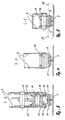
- Fig. 1 shows a simplified representation of the side support 6 of a vehicle seat and the bottom rail 7, which has a T-shaped profile in cross section, as can be seen from FIGS. 3 to 5.
- the roller 8 runs on the top surface of the bottom rail 7.
- the T-profile of the bottom rail is gripped on both sides by a tie rod 9, as shown in FIG. 5.
- the tie rod is fastened on the axis 10 of the roller 8.
- the axis 10 is mounted in the side carrier 6.
- FIG. 4 shows the clamping piece 11 which is non-positively clamped against the top surface of the bottom rail, whereby the tie rods 9 non-positively against the underside of the T-profile of the bottom rail 7 are tense. In this state, the roller 8 is lifted off the top surface of the floor rail (see cross section according to FIG. 5).
- roller carriage 12 In the rear area of the side support there is a roller carriage 12 with the two rollers 13 and 14.
- the roller carriage in turn has two tie rods 15, each of which engages under the T-profile of the bottom rail 7 from the side (see FIG. 3), the Tie rods with the wheel axles of the rollers 13, 14 and / or with the articulation axis 16 are firmly connected or are mounted tensile on these axes.
- the articulation lever 17 is also articulated on the carriage 12, the other end of which is connected to the side support 6 via the articulation axis 18. In this way, the roller carriage 12 is always assigned the position of the side support 6, even when the rear part of the side support 6 is raised (see FIG. 1) and the side support is moved along the bottom rail 7.
- the above-mentioned articulation lever 17 has the special feature that it has a pressure piece 20 by appropriate shaping and by side plates 19 which, when the rear region of the side member 6 is depressed, passes under a thrust bearing (in this case the articulation axis 16) and the carriage 12 upwards from the Bottom rail 7 pushes off so that the associated tie rods 15 brace against the underside of the T-profile of the bottom rail (cf. FIGS. 2 and 3).
- the articulation axis 16 also serves as a catch bolt for a catch hook 21 which is mounted in the rear part of the side support 6 and which, when the rear part is depressed, latches with the catch bolt (articulation axis 16).
- a V-shaped adjusting piece 22 is fastened to the inner sides of the side support 6, which overlap the articulation axis 16 when the rear part of the side support 6 is depressed and adjust with reference to the catch hook.
- the catch hook 21 can be released by means of a Bowden cable 23 against the closing force of the tension spring 24.
- FIG. 5 shows in cross section the advantageous manner in which a T-shaped floor rail can be laid on a vehicle floor with a carpet.
- the carpet which is indicated by the dash-dotted lines 25, can be connected to the T-profile on both sides, so that the floor rails are arranged flush with the floor covering (carpet).
Landscapes
- Engineering & Computer Science (AREA)
- Aviation & Aerospace Engineering (AREA)
- Transportation (AREA)
- Mechanical Engineering (AREA)
- Seats For Vehicles (AREA)
Applications Claiming Priority (2)
| Application Number | Priority Date | Filing Date | Title |
|---|---|---|---|
| DE19617935 | 1996-04-26 | ||
| DE19617935A DE19617935A1 (de) | 1996-04-26 | 1996-04-26 | Fahrzeugsitz mit einer Bodenschienenmontage |
Publications (2)
| Publication Number | Publication Date |
|---|---|
| EP0803396A2 true EP0803396A2 (fr) | 1997-10-29 |
| EP0803396A3 EP0803396A3 (fr) | 1998-10-07 |
Family
ID=7793332
Family Applications (1)
| Application Number | Title | Priority Date | Filing Date |
|---|---|---|---|
| EP97106335A Withdrawn EP0803396A3 (fr) | 1996-04-26 | 1997-04-17 | Siège de véhicule avec un montage de rails de sol |
Country Status (4)
| Country | Link |
|---|---|
| US (1) | US5915778A (fr) |
| EP (1) | EP0803396A3 (fr) |
| JP (1) | JPH1053050A (fr) |
| DE (1) | DE19617935A1 (fr) |
Cited By (5)
| Publication number | Priority date | Publication date | Assignee | Title |
|---|---|---|---|---|
| FR2771348A1 (fr) * | 1997-11-21 | 1999-05-28 | Faure Bertrand Equipements Sa | Ensemble d'assise pour vehicule comportant un siege amovible monte sur glissieres |
| FR2772685A1 (fr) * | 1997-12-22 | 1999-06-25 | Faure Bertrand Equipements Sa | Ensemble d'assise pour vehicule comportant un siege amovible monte sur glissieres |
| EP0925996A1 (fr) * | 1997-12-22 | 1999-06-30 | Bertrand Faure Equipements S.A. | Ensemble d'assise pour véhicule comportant un siège amovible monté sur glissières |
| FR2829440A1 (fr) * | 2001-09-07 | 2003-03-14 | Faurecia Sieges Automobile | Siege de vehicule et ensemble d'assise comportant un tel siege |
| FR2832105A1 (fr) * | 2001-11-09 | 2003-05-16 | Faurecia Sieges Automobile | Siege de vehicule comprenant un dispositif d'assistance et vehicule equipe d'un tel siege |
Families Citing this family (7)
| Publication number | Priority date | Publication date | Assignee | Title |
|---|---|---|---|---|
| US6250704B1 (en) * | 1999-08-12 | 2001-06-26 | Dura Automotive Systems Inc. | Release mechanism for fold and flip seat assembly |
| DE10014722B4 (de) * | 2000-03-24 | 2007-06-06 | Keiper Gmbh & Co.Kg | Befestigungsvorrichtung für einen Fahrzeugsitz |
| KR100340762B1 (ko) * | 2000-06-23 | 2002-06-20 | 허재건 | 자동차용 탈착식 시트 |
| DE10034008B4 (de) * | 2000-07-07 | 2012-04-19 | Volkswagen Ag | Einrichtung zur Verstellung und Arretierung eines in Längsrichtung verschiebbaren Sitzes |
| DE102004036402A1 (de) * | 2004-07-23 | 2006-03-16 | Volkswagen Ag | Sitzarretierung |
| DE102009039809A1 (de) | 2009-09-02 | 2011-03-03 | GM Global Technology Operations, Inc., Detroit | Führungsschiene für einen Kraftfahrzeugsitz eines Kraftfahrzeuges, Sitzanordnung in einem Kraftfahrzeug sowie Kraftfahrzeug |
| US10562409B2 (en) | 2018-07-05 | 2020-02-18 | Ford Global Technologies, Llc | Mounting hardware for vehicle structures |
Citations (1)
| Publication number | Priority date | Publication date | Assignee | Title |
|---|---|---|---|---|
| GB997741A (en) * | 1962-03-22 | 1965-07-07 | American Metal Prod | Seat track |
Family Cites Families (13)
| Publication number | Priority date | Publication date | Assignee | Title |
|---|---|---|---|---|
| DE617530C (de) * | 1933-01-10 | 1935-08-21 | Paul G Ehrhardt | Aus Stahlrohren bestehender, verstellbarer Sitz fuer Fahrzeuge |
| FR2338416A2 (fr) * | 1976-01-16 | 1977-08-12 | Faure Bertrand | Perfectionnements aux glissieres, notamment pour sieges de vehicule |
| DE3106821A1 (de) * | 1981-02-24 | 1982-09-02 | Bayerische Motoren Werke AG, 8000 München | In einem personenkraftwagen angeordneter sitz |
| JPS58108928U (ja) * | 1982-01-21 | 1983-07-25 | 日産自動車株式会社 | シ−トスライド装置 |
| DE3623007A1 (de) * | 1986-07-09 | 1988-01-28 | Keiper Recaro Gmbh Co | Gleitelement fuer sitzschienenpaare von fahrzeugsitzen |
| DE3635336A1 (de) * | 1986-10-17 | 1988-04-28 | Keiper Recaro Gmbh Co | Sitzschienenanordnung zum verbinden eines fahrzeugsitzes mit dem boden eines zugehoerigen fahrzeuges |
| JPH0639232B2 (ja) * | 1990-02-09 | 1994-05-25 | 株式会社大井製作所 | シートスライド装置 |
| JPH0742861Y2 (ja) * | 1991-06-28 | 1995-10-04 | 池田物産株式会社 | シートスライド装置 |
| JP3269208B2 (ja) * | 1993-09-22 | 2002-03-25 | アイシン精機株式会社 | シートのスライド装置 |
| US5368355A (en) * | 1993-10-04 | 1994-11-29 | General Motors Corporation | Vehicle seat having normal usage and storage positions |
| DE4404935B4 (de) * | 1994-02-11 | 2004-05-27 | Brose Fahrzeugteile Gmbh & Co. Kommanditgesellschaft, Coburg | Vorrichtung zum Verbinden eines Fahrzeugsitzes mit einem Fahrzeugboden |
| DE4408686C1 (de) * | 1994-03-15 | 1995-04-27 | Keiper Recaro Gmbh Co | Vorrichtung zum Verbinden eines Längsträgers eines Fahrzeugsitzes mit der Fahrzeugstruktur |
| AUPN395195A0 (en) * | 1995-07-04 | 1995-07-27 | Commonwealth Scientific And Industrial Research Organisation | Adjustable seat mounting mechanism |
-
1996
- 1996-04-26 DE DE19617935A patent/DE19617935A1/de not_active Ceased
-
1997
- 1997-04-17 EP EP97106335A patent/EP0803396A3/fr not_active Withdrawn
- 1997-04-23 JP JP9139051A patent/JPH1053050A/ja active Pending
- 1997-04-25 US US08/845,642 patent/US5915778A/en not_active Expired - Fee Related
Patent Citations (1)
| Publication number | Priority date | Publication date | Assignee | Title |
|---|---|---|---|---|
| GB997741A (en) * | 1962-03-22 | 1965-07-07 | American Metal Prod | Seat track |
Cited By (6)
| Publication number | Priority date | Publication date | Assignee | Title |
|---|---|---|---|---|
| FR2771348A1 (fr) * | 1997-11-21 | 1999-05-28 | Faure Bertrand Equipements Sa | Ensemble d'assise pour vehicule comportant un siege amovible monte sur glissieres |
| FR2772685A1 (fr) * | 1997-12-22 | 1999-06-25 | Faure Bertrand Equipements Sa | Ensemble d'assise pour vehicule comportant un siege amovible monte sur glissieres |
| EP0925996A1 (fr) * | 1997-12-22 | 1999-06-30 | Bertrand Faure Equipements S.A. | Ensemble d'assise pour véhicule comportant un siège amovible monté sur glissières |
| US6357814B1 (en) | 1997-12-22 | 2002-03-19 | Bertrand Faure Equipements Sa | Vehicle seat assembly comprising a removable seat assembled on guide rails |
| FR2829440A1 (fr) * | 2001-09-07 | 2003-03-14 | Faurecia Sieges Automobile | Siege de vehicule et ensemble d'assise comportant un tel siege |
| FR2832105A1 (fr) * | 2001-11-09 | 2003-05-16 | Faurecia Sieges Automobile | Siege de vehicule comprenant un dispositif d'assistance et vehicule equipe d'un tel siege |
Also Published As
| Publication number | Publication date |
|---|---|
| JPH1053050A (ja) | 1998-02-24 |
| DE19617935A1 (de) | 1997-10-30 |
| US5915778A (en) | 1999-06-29 |
| EP0803396A3 (fr) | 1998-10-07 |
Similar Documents
| Publication | Publication Date | Title |
|---|---|---|
| DE3222509C2 (de) | Teleskopführung für eine Lastenpritsche eines Schrägaufzuges für den Transport von Möbeln | |
| DE69403284T2 (de) | Lastträger für ein Kraftfahrzeug | |
| EP0121086B1 (fr) | Wagon de marchandises ferroviaire | |
| EP3599129B1 (fr) | Dispositif de table pour un véhicule automobile | |
| DE19815466A1 (de) | Be- und Entladegerät | |
| DE29810333U1 (de) | Sitzmodul | |
| EP1387775A2 (fr) | Structure de vehicule | |
| DE10036551A1 (de) | Vorrichtung zum Verankern eines Sitzes an einem Fahrzeugboden | |
| DE19617935A1 (de) | Fahrzeugsitz mit einer Bodenschienenmontage | |
| DE3911165A1 (de) | Sitzverschiebe-vorrichtung | |
| DE102015208351A1 (de) | Baueinheit, umfassend eine Sitzeinrichtung und eine Halterung für die Sitzeinrichtung, zur Anordnung in einem Schienenfahrzeug, Verfahren zum Überführen der Sitzeinrichtung von einer Verstaustellung in eine Gebrauchsstellung sowie Schienenfahrzeug mit mindestens einer Baueinheit | |
| EP1522455A2 (fr) | Dispositif de protection de chargement dans les unités de transport | |
| EP2338739B1 (fr) | Chariot de support de charge doté d'une ligne électrique | |
| DE19533374C2 (de) | Ablagefach im Bereich eines Mitteltunnels eines Kraftfahrzeuginnenraumes | |
| DE10312466B4 (de) | Ladesystem für einen Laderaum eines Kraftfahrzeuges | |
| EP3705330A1 (fr) | Structure de bâche pourvue de dispositif d'arrêt de montant coulissant | |
| DE19606196A1 (de) | Be- und Entladevorrichtung | |
| EP0679788A1 (fr) | Chariot ainsi qu'ensemble coulissant et rail | |
| DE202017106515U1 (de) | Ladebodeneinheit für ein Bestattungsfahrzeug | |
| DE102020126426A1 (de) | Aufbau eines Nutzfahrzeugs mit Schiebeverdeck | |
| DE3613461A1 (de) | Tragenlagerungsgestell | |
| EP4147685B1 (fr) | Dispositif de chargement pour cercueils | |
| DE29507027U1 (de) | Mobile Serviceeinrichtung | |
| DE19719292C2 (de) | Haltevorrichtung für eine Leiteranordnung auf einem Fahrzeugdach | |
| DE19930004A1 (de) | Kraftfahrzeug |
Legal Events
| Date | Code | Title | Description |
|---|---|---|---|
| PUAI | Public reference made under article 153(3) epc to a published international application that has entered the european phase |
Free format text: ORIGINAL CODE: 0009012 |
|
| AK | Designated contracting states |
Kind code of ref document: A2 Designated state(s): DE FR GB IT |
|
| PUAL | Search report despatched |
Free format text: ORIGINAL CODE: 0009013 |
|
| AK | Designated contracting states |
Kind code of ref document: A3 Designated state(s): DE FR GB IT |
|
| 17P | Request for examination filed |
Effective date: 19990311 |
|
| 17Q | First examination report despatched |
Effective date: 20050125 |
|
| GRAP | Despatch of communication of intention to grant a patent |
Free format text: ORIGINAL CODE: EPIDOSNIGR1 |
|
| STAA | Information on the status of an ep patent application or granted ep patent |
Free format text: STATUS: THE APPLICATION IS DEEMED TO BE WITHDRAWN |
|
| 18D | Application deemed to be withdrawn |
Effective date: 20060223 |