EP0803396A2 - Vehicle seat with a floor rail assembly - Google Patents
Vehicle seat with a floor rail assembly Download PDFInfo
- Publication number
- EP0803396A2 EP0803396A2 EP97106335A EP97106335A EP0803396A2 EP 0803396 A2 EP0803396 A2 EP 0803396A2 EP 97106335 A EP97106335 A EP 97106335A EP 97106335 A EP97106335 A EP 97106335A EP 0803396 A2 EP0803396 A2 EP 0803396A2
- Authority
- EP
- European Patent Office
- Prior art keywords
- floor
- profile
- seat
- vehicle seat
- rails
- Prior art date
- Legal status (The legal status is an assumption and is not a legal conclusion. Google has not performed a legal analysis and makes no representation as to the accuracy of the status listed.)
- Withdrawn
Links
- 230000000994 depressogenic effect Effects 0.000 claims description 9
- 238000005096 rolling process Methods 0.000 claims description 4
- 239000000969 carrier Substances 0.000 description 3
- 206010017577 Gait disturbance Diseases 0.000 description 1
- 230000005540 biological transmission Effects 0.000 description 1
- 238000011109 contamination Methods 0.000 description 1
- 238000009434 installation Methods 0.000 description 1
- 230000007257 malfunction Effects 0.000 description 1
- 239000000463 material Substances 0.000 description 1
- 238000007493 shaping process Methods 0.000 description 1
Images

Classifications
-
- B—PERFORMING OPERATIONS; TRANSPORTING
- B60—VEHICLES IN GENERAL
- B60N—SEATS SPECIALLY ADAPTED FOR VEHICLES; VEHICLE PASSENGER ACCOMMODATION NOT OTHERWISE PROVIDED FOR
- B60N2/00—Seats specially adapted for vehicles; Arrangement or mounting of seats in vehicles
- B60N2/005—Arrangement or mounting of seats in vehicles, e.g. dismountable auxiliary seats
- B60N2/015—Attaching seats directly to vehicle chassis
- B60N2/01508—Attaching seats directly to vehicle chassis using quick release attachments
- B60N2/01516—Attaching seats directly to vehicle chassis using quick release attachments with locking mechanisms
- B60N2/01583—Attaching seats directly to vehicle chassis using quick release attachments with locking mechanisms locking on transversal elements on the vehicle floor or rail, e.g. transversal rods
Definitions
- the invention relates to a vehicle seat with a floor rail assembly in the passenger compartment (loading space) of a vehicle.
- the vehicle seat e.g. in the form of benches
- the floor rail assembly is a self-contained (uniform) system.
- Such floor rails are designed as an upwardly open U-shaped slide or roller rails, in which the profile edges are drawn somewhat inwards, so that in the floor rails the side members of the seat frame of the vehicle seat are guided in a longitudinally displaceable manner by means of sliders or rollers and in optional positions along the Bottom rail can be locked.
- the locking is usually carried out by means of clamping screws or socket bolts, which are clamped in the U-shaped floor rails or inserted in pre-punched plug holes.
- a disadvantage of such systems is that the floor rails, which are open at the top, must be covered (for example by means of a carpet), particularly when transporting people, so that they do not represent a stumbling block for people or that narrow shoe heels cannot be stepped on. From a technical point of view, it is also desirable to cover the floor rails in order to avoid contamination of the rail running surfaces, which is necessary for precise sliding or roller guidance of the vehicle seats work with relatively narrow guide tolerances, since in this regard the floor rail fastening requires complete freedom from play and rattling, and it must also be ensured that, despite the narrow tolerances, converting the seat arrangements, ie changing and / or moving the seats in the floor rails, is always possible have to be.
- the object of the invention is to propose vehicle seats with a floor rail assembly, which are still free of play and rattle without an expensive precision guide and which are largely insensitive to dirt or the dangers associated with them when transporting people.
- the floor rails have a T-shaped cross-sectional profile
- the upper cover surface is closed and aligned substantially plane-parallel to the vehicle floor
- the side members of the seat each have tie rods, which preferably engage under the T-profile of the floor rails on both sides , wherein for the purpose of locking the vehicle seat, the side girders with the tie rods are pressed upwards by means of a lever mechanism from the floor rails in such a way that the tie rods clamp against the underside of the T-profile of the floor rails in a positive or non-positive manner.
- the proposed T-shaped floor rails can be built very flat, i.e. need only a very low installation height above the vehicle floor, as they are only gripped by the relatively flat tie rods (corresponding to the material thickness) of the side supports of the seat and the other guide means of the side supports (such as gliders or rollers) only run on the upper cover surface of the floor rails .
- the flat T-profiles of the floor rails are only so high in a practical design that they do not protrude from a carpet (or another floor covering) laid on both sides up to the floor rails. They do not pose a trip hazard.
- the upper, closed top surface of the T-profile also ensures that the floor rails become less dirty and that narrower heels cannot be stepped into the floor rails. Additional covering of the floor rails is not necessary.
- the lever mechanism for pushing off the side supports with the tie rods from the floor rails in the desired locking position is preferably carried out as follows according to subclaims 2 and 3.
- a roller In the front area of the side supports, a roller is provided, which rolls when the seat is moved on the cover surfaces of the T-profile of the floor rail, the lever mechanism being provided by the side support itself, which is raised in the rear area when the vehicle seat is moved, which means that front area of the side support is supported exclusively on the front roller, and which is pressed down with its rear area for the purpose of locking the vehicle seat, as a result of which a clamping piece fastened to the side support and positioned near the front roller between the side support and the bottom rail is non-positively is clamped against the top surface of the T-profile of the floor rail.
- Such a lever mechanism has a very large transmission ratio, so that the clamping force of the clamping piece against the floor rail is very high.
- the clamping force is absorbed by the respective tie rod that grips under the T-profile of the floor rail.
- the depressed rear part of the side carrier can latch with the T-profile of the floor rail by means of a releasable latching hook.
- a releasable latching hook Such a direct locking of the rear part of the side carrier on the floor rail is possible because the latching only exists when the seat is locked and the seat is no longer moved on the floor rails in its locked state.
- the rear part of the side brackets i.e. the rear part of the seat
- the rear area of the side brackets in this embodiment has no rollers or sliders or the like. owns.
- a further improved embodiment of the invention provides that the rear regions of the side carriers each have a rolling or sliding carriage which carries this region of the side carriers both in the raised state and in the depressed state.
- the roller or sliding carriage e.g. to arrange a support rod or an extendable gas pressure spring on which the rear part of the side supports is supported in the raised state.
- the rolling or sliding carriage by means of a linkage lever with the rear region of the side carrier is connected in such a way that a pressure piece of the articulation lever moves under a thrust bearing on the slide when the rear region of the side member is depressed and pushes the slide upward from the bottom rail, so that the associated tie rod or braces clamp against the underside of the T-profile of the bottom rail.
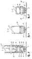
- Fig. 1 shows a simplified representation of the side support 6 of a vehicle seat and the bottom rail 7, which has a T-shaped profile in cross section, as can be seen from FIGS. 3 to 5.
- the roller 8 runs on the top surface of the bottom rail 7.
- the T-profile of the bottom rail is gripped on both sides by a tie rod 9, as shown in FIG. 5.
- the tie rod is fastened on the axis 10 of the roller 8.
- the axis 10 is mounted in the side carrier 6.
- FIG. 4 shows the clamping piece 11 which is non-positively clamped against the top surface of the bottom rail, whereby the tie rods 9 non-positively against the underside of the T-profile of the bottom rail 7 are tense. In this state, the roller 8 is lifted off the top surface of the floor rail (see cross section according to FIG. 5).
- roller carriage 12 In the rear area of the side support there is a roller carriage 12 with the two rollers 13 and 14.
- the roller carriage in turn has two tie rods 15, each of which engages under the T-profile of the bottom rail 7 from the side (see FIG. 3), the Tie rods with the wheel axles of the rollers 13, 14 and / or with the articulation axis 16 are firmly connected or are mounted tensile on these axes.
- the articulation lever 17 is also articulated on the carriage 12, the other end of which is connected to the side support 6 via the articulation axis 18. In this way, the roller carriage 12 is always assigned the position of the side support 6, even when the rear part of the side support 6 is raised (see FIG. 1) and the side support is moved along the bottom rail 7.
- the above-mentioned articulation lever 17 has the special feature that it has a pressure piece 20 by appropriate shaping and by side plates 19 which, when the rear region of the side member 6 is depressed, passes under a thrust bearing (in this case the articulation axis 16) and the carriage 12 upwards from the Bottom rail 7 pushes off so that the associated tie rods 15 brace against the underside of the T-profile of the bottom rail (cf. FIGS. 2 and 3).
- the articulation axis 16 also serves as a catch bolt for a catch hook 21 which is mounted in the rear part of the side support 6 and which, when the rear part is depressed, latches with the catch bolt (articulation axis 16).
- a V-shaped adjusting piece 22 is fastened to the inner sides of the side support 6, which overlap the articulation axis 16 when the rear part of the side support 6 is depressed and adjust with reference to the catch hook.
- the catch hook 21 can be released by means of a Bowden cable 23 against the closing force of the tension spring 24.
- FIG. 5 shows in cross section the advantageous manner in which a T-shaped floor rail can be laid on a vehicle floor with a carpet.
- the carpet which is indicated by the dash-dotted lines 25, can be connected to the T-profile on both sides, so that the floor rails are arranged flush with the floor covering (carpet).
Landscapes
- Engineering & Computer Science (AREA)
- Aviation & Aerospace Engineering (AREA)
- Transportation (AREA)
- Mechanical Engineering (AREA)
- Seats For Vehicles (AREA)
Abstract
Description
Die Erfindung betrifft einen Fahrzeugsitz mit einer Bodenschienenmontage in dem Fahrgastraum (Laderaum) eines Fahrzeuges.The invention relates to a vehicle seat with a floor rail assembly in the passenger compartment (loading space) of a vehicle.
Bei Fahrzeugen mit einem Fahrgastraum und/oder einem Laderaum, der wahlweise mit Fahrzeugsitzen je nach Bedarf in verschiedener Anzahl und/oder Reihenanordnung ausrüstbar oder wahlweise auch von einer Personenbeförderung auf Frachtbeförderung umrüstbar sein soll, bilden der Fahrzeugsitz (z,B. in form von Sitzbänken) mit seiner Bodenschienenmontage ein in sich geschlossenes (einheitliches) System.In vehicles with a passenger compartment and / or a loading space, which can be optionally equipped with vehicle seats in various numbers and / or rows, or optionally also convertible from passenger transport to freight transport, as required the vehicle seat (e.g. in the form of benches) with its floor rail assembly is a self-contained (uniform) system.
Es ist bekannt, bei Fahrzeugsitzen mit einer Bodenschienenmontage mindestens zwei, zueinander parallele Bodenschienen vorzusehen, die auf dem Fahrzeugboden befestigt sind. Solche Bodenschienen sind als nach oben offene U-förmige Gleit- oder Rollschienen ausgebildet, bei denen die Profilränder etwas nach innen eingezogen sind, so daß in den Bodenschienen die Seitenträger des Sitzgestelles des Fahrzeugsitzes mittels Gleitern oder Rollen längsverschiebbar geführt sind und in wahlweisen Positionen entlang der Bodenschiene arretierbar sind. Die Arretierung erfolgt üblicherweise mittels Klemmschrauben oder Steckbolzen, die in den U-förmigen Bodenschienen verklemmt oder in vorgestanzten Stecklöchern eingesteckt werden.It is known to provide at least two parallel floor rails, which are fastened to the vehicle floor, in vehicle seats with a floor rail assembly. Such floor rails are designed as an upwardly open U-shaped slide or roller rails, in which the profile edges are drawn somewhat inwards, so that in the floor rails the side members of the seat frame of the vehicle seat are guided in a longitudinally displaceable manner by means of sliders or rollers and in optional positions along the Bottom rail can be locked. The locking is usually carried out by means of clamping screws or socket bolts, which are clamped in the U-shaped floor rails or inserted in pre-punched plug holes.
Nachteilig bei solchen Systemen ist, daß insbesondere bei der Personenbeförderung die nach oben offenen Bodenschienen abgedeckt werden müssen (z.B. mittels eines Teppichbodens), damit sie für Personen keine Stolperfallen darstellen oder schmalere Schuhabsätze nicht in sie hineingetreten werden können. In technischer Hinsicht ist die Abdeckung der Bodenschienen ebenfalls erwünscht, um Verschmutzungen der Schienenlaufflächen zu vermeiden, die für eine präzise Gleit- oder Rollenführung der Fahrzeugsitze mit relativ engen Führungstoleranzen arbeiten, da diesbezüglich von der Bodenschienenbefestigung eine vollständige Spiel- und Klapperfreiheit verlangt wird und auch gewährleistet bleiben muß, daß trotz der engen Toleranzen das Umrüsten der Sitzanordnungen, d.h. das Auswechseln und/oder Verschieben der Sitze in den Bodenschienen stets leichtgängig möglich sein muß.A disadvantage of such systems is that the floor rails, which are open at the top, must be covered (for example by means of a carpet), particularly when transporting people, so that they do not represent a stumbling block for people or that narrow shoe heels cannot be stepped on. From a technical point of view, it is also desirable to cover the floor rails in order to avoid contamination of the rail running surfaces, which is necessary for precise sliding or roller guidance of the vehicle seats work with relatively narrow guide tolerances, since in this regard the floor rail fastening requires complete freedom from play and rattling, and it must also be ensured that, despite the narrow tolerances, converting the seat arrangements, ie changing and / or moving the seats in the floor rails, is always possible have to be.
Aufgabe der Erfindung ist es, Fahrzeugsitze mit einer Bodenschienenmontage vorzuschlagen, die ohne eine kostenaufwendige Präzisionsführung dennoch spiel- und klapperfrei sind und die weitgehend unempfindlich gegen Verschmutzungen oder von ihnen ausgehenden Gefahren bei der Personenbeförderung sind.The object of the invention is to propose vehicle seats with a floor rail assembly, which are still free of play and rattle without an expensive precision guide and which are largely insensitive to dirt or the dangers associated with them when transporting people.
Diese Aufgabe wird erfindungsgemäß dadurch gelöst, daß die Bodenschienen ein T-förmiges Querschnittsprofil aufweisen, dessen obere Deckfläche geschlossen und im wesentlichen planparallel zum Fahrzeugboden ausgerichtet ist, und daß die Seitenträger des Sitzes jeweils Zuganker aufweisen, die vorzugsweise beidseitig das T-Profil der Bodenschienen untergreifen, wobei zum Zwecke der Arretierung des Fahrzeugsitzes die Seitenträger mit den Zugankern mittels einer Hebelmechanik nach oben von den Bodenschienen abgedrückt werden derart, daß die Zuganker gegen die Unterseite des T-Profils der Bodenschienen form- oder kraftschlüssig verspannen.This object is achieved in that the floor rails have a T-shaped cross-sectional profile, the upper cover surface is closed and aligned substantially plane-parallel to the vehicle floor, and that the side members of the seat each have tie rods, which preferably engage under the T-profile of the floor rails on both sides , wherein for the purpose of locking the vehicle seat, the side girders with the tie rods are pressed upwards by means of a lever mechanism from the floor rails in such a way that the tie rods clamp against the underside of the T-profile of the floor rails in a positive or non-positive manner.
Es ist zunächst ein genereller Vorteil, daß die vorgeschlagenen T-förmigen Bodenschienen sehr flach gebaut sein können, d.h. nur eine sehr geringe Aufbauhöhe über dem Fahrzeugboden benötigen, da sie nur von den (entsprechend der Materialstärke) relativ flachen Zugankern der Seitenträger des Sitzes untergriffen werden und die übrigen Führungsmittel der Seitenträger (wie z.B. Gleiter oder Rollen) nur auf der oberen Deckfläche der Bodenschienen laufen.It is initially a general advantage that the proposed T-shaped floor rails can be built very flat, i.e. need only a very low installation height above the vehicle floor, as they are only gripped by the relatively flat tie rods (corresponding to the material thickness) of the side supports of the seat and the other guide means of the side supports (such as gliders or rollers) only run on the upper cover surface of the floor rails .
Die flachbauenden T-Profile der Bodenschienen sind in einer praxisgerechten Ausführung nur so hoch, daß sie einen beidseitig bis an die Bodenschienen verlegten Teppichboden (oder einen sonstigen Bodenbelag) nicht überragen. Eine Stolpergefahr geht von ihnen nicht aus.The flat T-profiles of the floor rails are only so high in a practical design that they do not protrude from a carpet (or another floor covering) laid on both sides up to the floor rails. They do not pose a trip hazard.
Auch gewährleistet die obere geschlossene Deckfläche des T-Profils, daß die Bodenschienen weniger verschmutzen und daß schmalere Schuhabsätze grundsätzlich nicht in die Bodenschienen hineingetreten werden können. Eine zusätzliche Abdeckung der Bodenschienen ist nicht erforderlich.The upper, closed top surface of the T-profile also ensures that the floor rails become less dirty and that narrower heels cannot be stepped into the floor rails. Additional covering of the floor rails is not necessary.
Die Idee, die Seitenträger des Sitzes (mit den die T-förmigen Bodenschienen untergreifenden Zugankern) zum Zwecke der Arretierung des Sitzes mittels einer Hebelmechnaik von den Bodenschienen abzudrücken, ermöglicht es, in jeder Arretierungsposition des Sitzes eine spiel- und klapperfreie Befestigung des Sitzes auf den Bodenschienen zu erreichen, ohne daß diese als Präzisionsführungen ausgebildet sein müssen. Das verbilligt das System der Bodenschienenmontage erheblich, denn die auf der oberen Deckfläche der Bodenschienen laufenden Gleiter oder Rollen bedürfen nur zum Zwecke der Verschiebung auf den Bodenschienen keine exakte Schienenführung. Zum Verschieben der Sitze genügt eine mit großen Toleranzen gebaute Schienenführung, die mit einem größeren Spiel und entsprechend größeren Klappergeräuschen behaftet ist, aber dafür entsprechend leichtgängiger ist und bleibt. Erst im arretierten Zustand des Sitzes, d.h. im Zustand der Personenbeförderung muß die Befestigung des Sitzes spiel- und klapperfrei sein. Das ist bei dem erfindungsgemäßen Sitz und seiner Bodenschienenmontage gewährleistet.The idea of pushing the side supports of the seat (with the tie rods underneath the T-shaped floor rails) for the purpose of locking the seat by means of a lever mechanism makes it possible to play and rattle-free in any locking position of the seat To achieve attachment of the seat on the floor rails without these need to be designed as precision guides. This considerably reduces the cost of the floor rail assembly system, because the glides or rollers running on the upper surface of the floor rails do not require exact rail guidance only for the purpose of moving them on the floor rails. To move the seats, a rail guide built with large tolerances is sufficient, which has a greater clearance and correspondingly larger rattling noises, but is and remains correspondingly smoother. Only when the seat is locked, ie in the state of passenger transport, must the seat be secured without play and rattling. This is guaranteed with the seat according to the invention and its bottom rail assembly.
Die vorgenannten großen Toleranzen, die die Schienenführung der Sitze erlaubt, ohne daß es bei der Sitzmontage und/oder beim Verschieben von Sitzanordnungen zu Funktionsstörungen kommt, hat auch den Vorteil, daß das neue System Unebenheiten des Fahrzeugbodens, auf dem die Bodenschienen befestigt sind, besser folgen kann.The abovementioned large tolerances, which allow the rails to be guided in the seats without malfunctions occurring during seat assembly and / or when displacing seat arrangements, also have the advantage that the new system improves unevenness in the vehicle floor on which the floor rails are attached can follow.
Die Hebelmechanik zum Abdrücken der Seitenträger mit den Zugankern von der Bodenschienen in der jeweils gewünschten Arretierungsposition ist gemäß den Unteransprüchen 2 und 3 bevorzugt wie folgt ausgeführt.The lever mechanism for pushing off the side supports with the tie rods from the floor rails in the desired locking position is preferably carried out as follows according to subclaims 2 and 3.
Im vorderen Bereich der Seitenträger sind jeweils eine Laufrolle vorgesehen, die beim Verschieben des Sitzes auf den Deckflächen des T-Profils der Bodenschiene abrollt, wobei die Hebelmechanik durch den Seitenträger selbst gegeben ist, der beim Verschieben des Fahrzeugsitzes im hinteren Bereich angehoben wird, wodurch der vordere Bereich des Seitenträgers sich ausschließlich auf der vorderen Rolle abstützt, und der zum Zwecke der Arretierung des Fahrzeugsitzes mit seinem hinteren Bereich niedergedrückt wird, wodurch ein an dem Seitenträger befestigtes Klemmstück, das nahe der vorderen Laufrolle zwischen dem Seitenträger und der Bodenschiene positioniert ist, kraftschlüssig gegen die obere Deckfläche des T-Profils der Bodenschiene geklemmt wird.In the front area of the side supports, a roller is provided, which rolls when the seat is moved on the cover surfaces of the T-profile of the floor rail, the lever mechanism being provided by the side support itself, which is raised in the rear area when the vehicle seat is moved, which means that front area of the side support is supported exclusively on the front roller, and which is pressed down with its rear area for the purpose of locking the vehicle seat, as a result of which a clamping piece fastened to the side support and positioned near the front roller between the side support and the bottom rail is non-positively is clamped against the top surface of the T-profile of the floor rail.
Eine derartige Hebelmechanik hat ein sehr großes Übersetzungsverhältnis, so daß die Klemmkraft des Klemmstückes gegen die Bodenschiene sehr hoch ist. Die Klemmkraft wird durch den jeweiligen Zuganker, der das T-Profil der Bodenschiene untergreift, abgefangen.Such a lever mechanism has a very large transmission ratio, so that the clamping force of the clamping piece against the floor rail is very high. The clamping force is absorbed by the respective tie rod that grips under the T-profile of the floor rail.
Gemäß dem Unteranspruch 3 kann der niedergedrückte hintere Teil des Seitenträgers mittels eines lösbaren Rasthakens mit dem T-Profil der Bodenschiene verrasten. Eine solche direkte Verrastung des hinteren Teils des Seitenträgers auf der Bodenschiene ist möglich, da die Verrastung nur im Arretierungszustand des Sitzes besteht und der Sitz in seinem Arretierungszustand nicht mehr auf den Bodenschienen verschoben wird.According to subclaim 3, the depressed rear part of the side carrier can latch with the T-profile of the floor rail by means of a releasable latching hook. Such a direct locking of the rear part of the side carrier on the floor rail is possible because the latching only exists when the seat is locked and the seat is no longer moved on the floor rails in its locked state.
Andererseits muß bei der vorgenannten Ausführungsform der Erfindung der hintere Teil der Seitenträger (d.h. der hintere Teil des Sitzes) beim Verschieben auf den Bodenschienen im angehobenen Zustand manuell getragen werden, da der hintere Bereich der Seitenträger bei dieser Ausführungsform keine Rollen oder Gleitstücke o.dgl. besitzt.On the other hand, in the aforementioned embodiment of the invention, the rear part of the side brackets (i.e. the rear part of the seat) has to be carried manually when being moved on the floor rails in the raised state, since the rear area of the side brackets in this embodiment has no rollers or sliders or the like. owns.
Nach Anspruch 4 sieht eine weiter verbesserte Ausführungsform der Erfindung vor, daß die hinteren Bereiche der Seitenträger jeweils einen Roll- oder Schiebeschlitten aufweisen, der diesen Bereich der Seitenträger sowohl im angehobenen Zustand als auch im niedergedrückten Zustand trägt. Zu diesem Zweck ist zwischen dem Roll- oder Schiebeschlitten und dem hinteren Bereich der Seitenträger z.B. ein Traggestänge oder eineausfahrbare Gasdruckfeder anzuordnen, auf die sich der hintere Teil der Seitenträger im angehobenen Zustand abstützt.According to claim 4, a further improved embodiment of the invention provides that the rear regions of the side carriers each have a rolling or sliding carriage which carries this region of the side carriers both in the raised state and in the depressed state. For this purpose, between the roller or sliding carriage and the rear area of the side supports e.g. to arrange a support rod or an extendable gas pressure spring on which the rear part of the side supports is supported in the raised state.
Im niedergedrückten Zustand muß der hintere Bereich der Seitenträger mit dem Roll- oder Schiebeschlitten zug- und druckfest verrasten. Damit dies stets funktionssicher erfolgen kann ist nach Anspruch 4 vorgesehen, daß der Roll- oder Schiebeschlitten mittels eines Anlenkhebels mit dem hinteren Bereich des Seitenträgers verbunden ist derart, daß ein Druckstück des Anlenkhebels beim Niederdrücken des hinteren Bereichs des Seitenträgers ein Drucklager am Schlitten unterfährt und den Schlitten nach oben von der Bodenschiene abdrückt, so daß sich der oder die zugeordneten Zuganker gegen die Unterseite des T-Profils der Bodenschiene verspannen.In the depressed state, the rear area of the side carriers must lock with the roller or sliding carriage so that they are tensile and compressive. So that this can always be done reliably, it is provided according to claim 4 that the rolling or sliding carriage by means of a linkage lever with the rear region of the side carrier is connected in such a way that a pressure piece of the articulation lever moves under a thrust bearing on the slide when the rear region of the side member is depressed and pushes the slide upward from the bottom rail, so that the associated tie rod or braces clamp against the underside of the T-profile of the bottom rail.
Nachfolgend wird ein Ausführungsbeispiel der Erfindung anhand der Zeichnungen näher beschrieben. Es zeigen:
- Fig. 1 und 2
- die Seitenansicht eines Seitenträgers eines Fahrzeugsitzes im verschiebbaren Zustand (Fig. 1) und im arretierten Zustand (Fig. 2),
- Fig. 3, 4 und 5
- Querschnitte durch den Seitenträger gemäß Fig. 1 und 2 entlang den Schnittlinien A-A, B-B und C-C.
- 1 and 2
- the side view of a side member of a vehicle seat in the displaceable state (Fig. 1) and in the locked state (Fig. 2),
- 3, 4 and 5
- Cross sections through the side support according to FIGS. 1 and 2 along the section lines AA, BB and CC.
Fig. 1 zeigt in vereinfachter Darstellung den Seitenträger 6 eines Fahrzeugsitzes und die Bodenschiene 7, die im Querschnitt ein T-förmiges Profil besitzt, wie dies aus den Fig. 3 bis 5 ersichtlich ist.Fig. 1 shows a simplified representation of the
Im vorderen Bereich des Seitenträgers 6 und im angehobenen (entarretierten) Zustand des Seitenträgers läuft die Rolle 8 auf der Deckfläche der Bodenschiene 7. Das T-Profil der Bodenschiene wird beidseitig von je einem Zuganker 9 untergriffen, wie dies die Fig. 5 zeigt. Der Zuganker ist auf der Achse 10 der Laufrolle 8 befestigt. Die Achse 10 ist in dem Seitenträger 6 gelagert.In the front area of the
Nahe der vorderen Laufrolle 8 ist zwischen dem Seitenträger 6 und der Bodenschiene 7 ein Klemmstück 11, z.B. ein elastischer Gummiblock, positioniert, der kraftschlüssig gegen die Deckfläche der Bodenschiene 7 geklemmt ist, sobald der hintere Teil des Seitenträgers niedergedrückt ist. Vergl. hierzu Fig. 2 und die Querschnitte gemäß Fig. 4 und Fig. 5. Die Fig. 4 zeigt das Klemmstück 11, das kraftschlüssig gegen die Deckfläche der Bodenschiene geklemmt ist, wodurch die Zuganker 9 kraftschlüssig gegen die Unterseite des T-Profils der Bodenschiene 7 verspannt sind. In diesem Zustand ist die Laufrolle 8 von der Deckfläche der Bodenschiene abgehoben (vergl. Querschnitt gemäß Fig. 5).Near the
Im hinteren Bereich des Seitenträgers befindet sich ein Rollschlitten 12 mit den beiden Laufrollen 13 und 14. Der Rollschlitten besitzt wiederum zwei Zuganker 15, die von der Seite her jeweils das T-Profil der Bodenschiene 7 untergreifen (vergl. Fig. 3), wobei die Zuganker mit den Laufradachsen der Laufrollen 13, 14 und/oder mit der Anlenkachse 16 fest verbunden sind bzw. auf diesen Achsen zugfest gelagert sind.In the rear area of the side support there is a
Mittels der Anlenkachse 16 ist zugleich der Anlenkhebel 17 an dem Schlitten 12 angelenkt, dessen anderes Ende über die Anlenkachse 18 mit dem Seitenträger 6 verbunden ist. Auf diese Weise ist der Rollschlitten 12 dem Seitenträger 6 stets positionsmäßig zugeordnet, auch wenn der hintere Teil des Seitenträgers 6 angehoben ist (vergl. Fig. 1) und der Seitenträger entlang der Bodenschiene 7 verschoben wird.By means of the
Im angehobenen Zustand wird der hintere Teil des Seitenträgers von einer Gasdruckfeder 26 getragen, so daß das manuelle Tragen des hinteren Teils des Sitzes beim Verschieben auf den Bodenschienen entfällt.In the raised state, the rear part of the side member is supported by a
Der vorgenannte Anlenkhebel 17 hat die Besonderheit, daß er durch entsprechende Formgebung und durch Seitenbleche 19 ein Druckstück 20 besitzt, das beim Niederdrücken des hinteren Bereichs des Seitenträgers 6 ein Drucklager (in diesem Fall die Anlenkachse 16) unterfährt und den Schlitten 12 nach oben von der Bodenschiene 7 abdrückt, so daß sich die zugeordneten Zuganker 15 gegen die Unterseite des T-Profils der Bodenschiene verspannen (vergl. hierzu Fig. 2 und Fig. 3).The above-mentioned
Die Anlenkachse 16 dient zugleich als Fangbolzen für einen Fanghaken 21, der im hinteren Teil des Seitenträgers 6 gelagert ist und beim Niederdrücken des hinteren Teils mit dem Fangbolzen (Anlenkachse 16) verrastet. Damit dies störungsfrei erfolgt, ist je ein V-förmiges Justierstück 22 an den Innenseiten des Seitenträgers 6 befestigt, die beim Niederdrücken des hinteren Teils des Seitenträgers 6 die Anlenkachse 16 übergreifen und mit Bezug auf den Fanghaken justieren.The
Der Fanghaken 21 kann mittels eines Bowdenzuges 23 gegen die Schließkraft der Zugfeder 24 gelöst werden.The
Fig. 5 zeigt im Querschnitt, auf welche vorteilhafte Weise eine T-förmige Bodenschiene auf einem Fahrzeugboden mit einem Teppichboden verlegt werden kann. Beidseitig an das T-Profil kann der Teppichboden, der durch die strichpunktierten Linien 25 angedeutet ist, angeschlossen werden, so daß die Bodenschienen nahezu flächenbündig in dem Bodenbelag (Teppichboden) versenkt angeordnet sind. Hierdurch und infolge der nach oben geschlossenen Deckfläche der Bodenschienen ergeben sich die geringsten Gefahren für Personen und/oder die Verschmutzung der Bodenschienen. Da Teppichböden üblicherweise mit einem hochstehenden, jedoch leicht deformierbaren Flor oder einer Teppichschlinge versehen sind, behindert ein direkt an das Profil der Bodenschiene anschließender Teppichboden in keiner Weise die Fanghaken 9 und 15, die beim Verschieben eines Fahrzeugsitzes auf den Bodenschienen den Flor bzw. die Schlingen des Teppichbodens leicht zurückdrücken.FIG. 5 shows in cross section the advantageous manner in which a T-shaped floor rail can be laid on a vehicle floor with a carpet. The carpet, which is indicated by the dash-dotted
Claims (4)
dadurch gekennzeichnet,
characterized,
dadurch gekennzeichnet,
characterized,
dadurch gekennzeichnet,
characterized,
dadurch gekennzeichnet,
characterized,
Applications Claiming Priority (2)
| Application Number | Priority Date | Filing Date | Title |
|---|---|---|---|
| DE19617935A DE19617935A1 (en) | 1996-04-26 | 1996-04-26 | Vehicle seat with a floor rail assembly |
| DE19617935 | 1996-04-26 |
Publications (2)
| Publication Number | Publication Date |
|---|---|
| EP0803396A2 true EP0803396A2 (en) | 1997-10-29 |
| EP0803396A3 EP0803396A3 (en) | 1998-10-07 |
Family
ID=7793332
Family Applications (1)
| Application Number | Title | Priority Date | Filing Date |
|---|---|---|---|
| EP97106335A Withdrawn EP0803396A3 (en) | 1996-04-26 | 1997-04-17 | Vehicle seat with a floor rail assembly |
Country Status (4)
| Country | Link |
|---|---|
| US (1) | US5915778A (en) |
| EP (1) | EP0803396A3 (en) |
| JP (1) | JPH1053050A (en) |
| DE (1) | DE19617935A1 (en) |
Cited By (5)
| Publication number | Priority date | Publication date | Assignee | Title |
|---|---|---|---|---|
| FR2771348A1 (en) * | 1997-11-21 | 1999-05-28 | Faure Bertrand Equipements Sa | Securing assembly for fixing removable vehicle seat on to slide |
| FR2772685A1 (en) * | 1997-12-22 | 1999-06-25 | Faure Bertrand Equipements Sa | Removable vehicle seat mounted on guide rails |
| EP0925996A1 (en) * | 1997-12-22 | 1999-06-30 | Bertrand Faure Equipements S.A. | Vehicle seat assembly with removable seat mounted on slides |
| FR2829440A1 (en) * | 2001-09-07 | 2003-03-14 | Faurecia Sieges Automobile | Vehicle seat comprises seat part pivoted at front around rotational axis, two lockable rear bases and fold down back able to unlock bases when folded forwards |
| FR2832105A1 (en) * | 2001-11-09 | 2003-05-16 | Faurecia Sieges Automobile | Vehicle seat comprises seat part and aid device comprising actuator, with one end pivoted on seat part, and connecting rod with one end pivoted on seat part and second end pivoted on actuator second end |
Families Citing this family (7)
| Publication number | Priority date | Publication date | Assignee | Title |
|---|---|---|---|---|
| US6250704B1 (en) * | 1999-08-12 | 2001-06-26 | Dura Automotive Systems Inc. | Release mechanism for fold and flip seat assembly |
| DE10014722B4 (en) * | 2000-03-24 | 2007-06-06 | Keiper Gmbh & Co.Kg | Fastening device for a vehicle seat |
| KR100340762B1 (en) * | 2000-06-23 | 2002-06-20 | 허재건 | Seat being easy to attach and detach for car |
| DE10034008B4 (en) * | 2000-07-07 | 2012-04-19 | Volkswagen Ag | Device for adjusting and locking a longitudinally displaceable seat |
| DE102004036402A1 (en) * | 2004-07-23 | 2006-03-16 | Volkswagen Ag | Car seat locking device, has clamping mechanism provided between lower seat rail section and seat, and elbow levers and deflecting levers stand in effective connection with clamping jaws at rail section |
| DE102009039809A1 (en) | 2009-09-02 | 2011-03-03 | GM Global Technology Operations, Inc., Detroit | Guide rail for motor vehicle seat, has attachment base provided with socket for covering motor vehicle floor mat i.e. carpet, and guiding section arranged above socket, where socket is formed by lip arranged at distance from base |
| US10562409B2 (en) | 2018-07-05 | 2020-02-18 | Ford Global Technologies, Llc | Mounting hardware for vehicle structures |
Citations (1)
| Publication number | Priority date | Publication date | Assignee | Title |
|---|---|---|---|---|
| GB997741A (en) * | 1962-03-22 | 1965-07-07 | American Metal Prod | Seat track |
Family Cites Families (13)
| Publication number | Priority date | Publication date | Assignee | Title |
|---|---|---|---|---|
| DE617530C (en) * | 1933-01-10 | 1935-08-21 | Paul G Ehrhardt | Adjustable seat for vehicles made of steel tubes |
| FR2338416A2 (en) * | 1976-01-16 | 1977-08-12 | Faure Bertrand | IMPROVEMENTS IN SLIDES, ESPECIALLY FOR VEHICLE SEATS |
| DE3106821A1 (en) * | 1981-02-24 | 1982-09-02 | Bayerische Motoren Werke AG, 8000 München | Seat arranged in a passenger vehicle |
| JPS58108928U (en) * | 1982-01-21 | 1983-07-25 | 日産自動車株式会社 | Seat slide device |
| DE3623007A1 (en) * | 1986-07-09 | 1988-01-28 | Keiper Recaro Gmbh Co | Sliding element for pairs of seat rails for vehicle seats |
| DE3635336A1 (en) * | 1986-10-17 | 1988-04-28 | Keiper Recaro Gmbh Co | SEAT RAIL ARRANGEMENT FOR CONNECTING A VEHICLE SEAT TO THE BOTTOM OF AN RELATED VEHICLE |
| JPH0639232B2 (en) * | 1990-02-09 | 1994-05-25 | 株式会社大井製作所 | Seat slide device |
| JPH0742861Y2 (en) * | 1991-06-28 | 1995-10-04 | 池田物産株式会社 | Seat slide device |
| JP3269208B2 (en) * | 1993-09-22 | 2002-03-25 | アイシン精機株式会社 | Sheet slide device |
| US5368355A (en) * | 1993-10-04 | 1994-11-29 | General Motors Corporation | Vehicle seat having normal usage and storage positions |
| DE4404935B4 (en) * | 1994-02-11 | 2004-05-27 | Brose Fahrzeugteile Gmbh & Co. Kommanditgesellschaft, Coburg | Device for connecting a vehicle seat to a vehicle floor |
| DE4408686C1 (en) * | 1994-03-15 | 1995-04-27 | Keiper Recaro Gmbh Co | Device for connecting a longitudinal member of a vehicle seat to the vehicle structure |
| AUPN395195A0 (en) * | 1995-07-04 | 1995-07-27 | Commonwealth Scientific And Industrial Research Organisation | Adjustable seat mounting mechanism |
-
1996
- 1996-04-26 DE DE19617935A patent/DE19617935A1/en not_active Ceased
-
1997
- 1997-04-17 EP EP97106335A patent/EP0803396A3/en not_active Withdrawn
- 1997-04-23 JP JP9139051A patent/JPH1053050A/en active Pending
- 1997-04-25 US US08/845,642 patent/US5915778A/en not_active Expired - Fee Related
Patent Citations (1)
| Publication number | Priority date | Publication date | Assignee | Title |
|---|---|---|---|---|
| GB997741A (en) * | 1962-03-22 | 1965-07-07 | American Metal Prod | Seat track |
Cited By (6)
| Publication number | Priority date | Publication date | Assignee | Title |
|---|---|---|---|---|
| FR2771348A1 (en) * | 1997-11-21 | 1999-05-28 | Faure Bertrand Equipements Sa | Securing assembly for fixing removable vehicle seat on to slide |
| FR2772685A1 (en) * | 1997-12-22 | 1999-06-25 | Faure Bertrand Equipements Sa | Removable vehicle seat mounted on guide rails |
| EP0925996A1 (en) * | 1997-12-22 | 1999-06-30 | Bertrand Faure Equipements S.A. | Vehicle seat assembly with removable seat mounted on slides |
| US6357814B1 (en) | 1997-12-22 | 2002-03-19 | Bertrand Faure Equipements Sa | Vehicle seat assembly comprising a removable seat assembled on guide rails |
| FR2829440A1 (en) * | 2001-09-07 | 2003-03-14 | Faurecia Sieges Automobile | Vehicle seat comprises seat part pivoted at front around rotational axis, two lockable rear bases and fold down back able to unlock bases when folded forwards |
| FR2832105A1 (en) * | 2001-11-09 | 2003-05-16 | Faurecia Sieges Automobile | Vehicle seat comprises seat part and aid device comprising actuator, with one end pivoted on seat part, and connecting rod with one end pivoted on seat part and second end pivoted on actuator second end |
Also Published As
| Publication number | Publication date |
|---|---|
| DE19617935A1 (en) | 1997-10-30 |
| US5915778A (en) | 1999-06-29 |
| JPH1053050A (en) | 1998-02-24 |
| EP0803396A3 (en) | 1998-10-07 |
Similar Documents
| Publication | Publication Date | Title |
|---|---|---|
| DE3222509C2 (en) | Telescopic guide for a load platform of an inclined lift for the transport of furniture | |
| DE69403284T2 (en) | Load carriers for a motor vehicle | |
| EP0121086B1 (en) | Railway freight wagon | |
| EP3599129B1 (en) | Table device for a motor vehicle | |
| DE19815466A1 (en) | Automotive luggage boot with electric motor spindle-driven lifting platform | |
| EP0803396A2 (en) | Vehicle seat with a floor rail assembly | |
| DE29810333U1 (en) | Seating module | |
| EP1387775A2 (en) | Vehicle structure | |
| DE10036551A1 (en) | Car seat anchorage of floor rail and slide uses slide of end hinged elements to permit slide movement even in torqued rail assisted by seat-fitted holder engaging floor rail holes. | |
| DE3911165A1 (en) | SEAT SLIDING DEVICE | |
| EP1522455A2 (en) | Device for securing loads in transportation units | |
| DE19533374C2 (en) | Storage compartment in the area of a central tunnel of a motor vehicle interior | |
| DE10312466B4 (en) | Charging system for a load compartment of a motor vehicle | |
| EP3705330A1 (en) | Canvas cover with middle stanchion locking | |
| DE19606196A1 (en) | Light goods vehicle loading system has telescopic rails within vehicle | |
| EP2338739A1 (en) | Sliding load carrier with an electric circuit | |
| DE102020102186A1 (en) | Locking system for detachable fastening of a stanchion on a utility vehicle | |
| EP0679788A1 (en) | Trolley as well as rail and sliding assembly | |
| DE202017106515U1 (en) | Loading floor unit for a funeral vehicle | |
| DE102020126426A1 (en) | Construction of a commercial vehicle with a sliding roof | |
| DE3613461A1 (en) | Stretcher-bearing frame | |
| EP4147685B1 (en) | Casket loading device | |
| DE29507027U1 (en) | Mobile service facility | |
| DE19719292C2 (en) | Holding device for a conductor arrangement on a vehicle roof | |
| DE19930004A1 (en) | Vehicle with roof rack, having two guides with gap opening outwards in roof region for carrier system |
Legal Events
| Date | Code | Title | Description |
|---|---|---|---|
| PUAI | Public reference made under article 153(3) epc to a published international application that has entered the european phase |
Free format text: ORIGINAL CODE: 0009012 |
|
| AK | Designated contracting states |
Kind code of ref document: A2 Designated state(s): DE FR GB IT |
|
| PUAL | Search report despatched |
Free format text: ORIGINAL CODE: 0009013 |
|
| AK | Designated contracting states |
Kind code of ref document: A3 Designated state(s): DE FR GB IT |
|
| 17P | Request for examination filed |
Effective date: 19990311 |
|
| 17Q | First examination report despatched |
Effective date: 20050125 |
|
| GRAP | Despatch of communication of intention to grant a patent |
Free format text: ORIGINAL CODE: EPIDOSNIGR1 |
|
| STAA | Information on the status of an ep patent application or granted ep patent |
Free format text: STATUS: THE APPLICATION IS DEEMED TO BE WITHDRAWN |
|
| 18D | Application deemed to be withdrawn |
Effective date: 20060223 |