EP0803331B1 - Toggle clamp for car bodywork construction - Google Patents
Toggle clamp for car bodywork construction Download PDFInfo
- Publication number
- EP0803331B1 EP0803331B1 EP97104333A EP97104333A EP0803331B1 EP 0803331 B1 EP0803331 B1 EP 0803331B1 EP 97104333 A EP97104333 A EP 97104333A EP 97104333 A EP97104333 A EP 97104333A EP 0803331 B1 EP0803331 B1 EP 0803331B1
- Authority
- EP
- European Patent Office
- Prior art keywords
- piston rod
- toggle
- grip holder
- section
- switches
- Prior art date
- Legal status (The legal status is an assumption and is not a legal conclusion. Google has not performed a legal analysis and makes no representation as to the accuracy of the status listed.)
- Expired - Lifetime
Links
- 238000010276 construction Methods 0.000 title claims description 4
- 230000001939 inductive effect Effects 0.000 claims description 7
- 238000007789 sealing Methods 0.000 claims description 3
- 239000000428 dust Substances 0.000 claims description 2
- 239000011796 hollow space material Substances 0.000 claims 1
- 238000005516 engineering process Methods 0.000 description 6
- 238000004519 manufacturing process Methods 0.000 description 3
- 238000000034 method Methods 0.000 description 2
- 230000000149 penetrating effect Effects 0.000 description 2
- 229910000831 Steel Inorganic materials 0.000 description 1
- 230000006978 adaptation Effects 0.000 description 1
- XAGFODPZIPBFFR-UHFFFAOYSA-N aluminium Chemical compound [Al] XAGFODPZIPBFFR-UHFFFAOYSA-N 0.000 description 1
- 229910052782 aluminium Inorganic materials 0.000 description 1
- 230000015572 biosynthetic process Effects 0.000 description 1
- 230000000295 complement effect Effects 0.000 description 1
- 230000002950 deficient Effects 0.000 description 1
- 238000005553 drilling Methods 0.000 description 1
- 238000005755 formation reaction Methods 0.000 description 1
- 238000001746 injection moulding Methods 0.000 description 1
- 239000007788 liquid Substances 0.000 description 1
- 230000007257 malfunction Effects 0.000 description 1
- 239000012778 molding material Substances 0.000 description 1
- 239000007921 spray Substances 0.000 description 1
- 239000010959 steel Substances 0.000 description 1
Images
Classifications
-
- B—PERFORMING OPERATIONS; TRANSPORTING
- B25—HAND TOOLS; PORTABLE POWER-DRIVEN TOOLS; MANIPULATORS
- B25B—TOOLS OR BENCH DEVICES NOT OTHERWISE PROVIDED FOR, FOR FASTENING, CONNECTING, DISENGAGING OR HOLDING
- B25B5/00—Clamps
- B25B5/16—Details, e.g. jaws, jaw attachments
-
- B—PERFORMING OPERATIONS; TRANSPORTING
- B25—HAND TOOLS; PORTABLE POWER-DRIVEN TOOLS; MANIPULATORS
- B25B—TOOLS OR BENCH DEVICES NOT OTHERWISE PROVIDED FOR, FOR FASTENING, CONNECTING, DISENGAGING OR HOLDING
- B25B5/00—Clamps
- B25B5/06—Arrangements for positively actuating jaws
- B25B5/12—Arrangements for positively actuating jaws using toggle links
- B25B5/122—Arrangements for positively actuating jaws using toggle links with fluid drive
-
- Y—GENERAL TAGGING OF NEW TECHNOLOGICAL DEVELOPMENTS; GENERAL TAGGING OF CROSS-SECTIONAL TECHNOLOGIES SPANNING OVER SEVERAL SECTIONS OF THE IPC; TECHNICAL SUBJECTS COVERED BY FORMER USPC CROSS-REFERENCE ART COLLECTIONS [XRACs] AND DIGESTS
- Y10—TECHNICAL SUBJECTS COVERED BY FORMER USPC
- Y10S—TECHNICAL SUBJECTS COVERED BY FORMER USPC CROSS-REFERENCE ART COLLECTIONS [XRACs] AND DIGESTS
- Y10S269/00—Work holders
- Y10S269/903—Work holder for electrical circuit assemblages or wiring systems
Definitions
- the invention relates to a toggle lever clamping device for the body shop with a rectangular in a cross-section perpendicular to the longitudinal axis of the piston rod cross-section, which is constructed from two housing parts, and with an axially extending to the cylinder-side end of the clamping head, in which an alternating on both sides by means of pressure medium pressure, in particular by air pressure to be acted upon pistons, which are guided in a longitudinally displaceable and sealing manner and which axially engages through the cylinder and a cavity of the clamping head with its piston rod, with a toggle joint arrangement which is coupled to a clamping arm being attached to the free end of the piston rod, with limit switches or Position transmitters in the form of microswitches, inductive switches, pneumatic switches or sensors which are integrated in a space of the clamping head, the switches being adjustable relative to one another and forming a cover for the same End holder are arranged and fastened as an overall interchangeable query cassette in the form of a board in the area of a slot in the
- Such a toggle lever tensioning device forms the subject of the applicant declining DE 93 11 132.0 U1 and the same European Patent application 0 636 449 (94 105 296.1-2302).
- no slot is provided, while in the embodiment 8 the cassette is grown from the side.
- DE-U-90 16 781.3 describes a tensioning device with an adjusting unit, Tension arm, end position interrogation devices and actuator stem with which the tension arm directly or indirectly between the end position sensing elements predetermined end positions is pivotable, previously known.
- the End position query elements are in a separate, with the clamping device Detachably connected housing in addition to an axial in this housing guided and adjustable sensor rod provided with position transmitter, which extends parallel to a housing connection surface and with its upper end protrudes from the housing, between the and the Position rod one with the upper end and the control rod axially fixed Driver crossbar is arranged.
- the end position query elements are in the housing is arranged adjustable in relation to the position transmitter.
- This Clamping device is arranged with a clamping arm in a on the drive unit fork-like head piece pivotally mounted.
- the case is on the Clamping arm side or the side of the device remote from the clamping arm with its housing connection surface arranged, the entrainer from the Guide rod between the fork parts of the head piece to the control rod extends.
- At least in one fork part of the head piece is laterally and parallel to the control rod a longitudinal slot and on the longitudinal slot side of the device arranged the housing, which is between the upper end of the Sensor rod and the actuator cross bar extending through extends the longitudinal slot.
- the control rod is with the tension arm from the drive unit simultaneously rotating and movable in the axial direction.
- the housing is arranged on one of the two sides of the device remote from the swivel range, the driver crossbar with the adjusting rod and / or the tension arm is rotatably connected.
- the connecting rod end of the driver crossbar on the rod side is fork-shaped.
- DE 30 22 376 C2 describes a toggle lever clamping device for clamping of workpieces, in particular body parts, consisting of a Pressure cylinder with double-acting piston and piston rod, previously known, the end of which is provided with a head piece which is in one on the cylinder guided axially attached guide piece and a hinged intermediate member movable with one on the guide piece on one side Swivel-mounted tension lever connected and via a flat guide is supported on the guide piece, this flat guide in one Plane is parallel to the one through the piston rod axis Level and on the side facing away from the swivel joint of the tensioning lever is arranged.
- the flat guide is on a maximum inner surface of the piston rod axis Guide piece arranged.
- a Stroke control element arranged near the flat guide.
- the invention has for its object a toggle lever device in the genre-presupposed kind in such a way that they do not only from the back, but also from all four sides of device parts can be added while maintaining the well-known cassette technology Advantages.
- the query cassette is removed from the Back of the tensioner housing through a narrow, slit-shaped recess inserted into the housing.
- the query cassette is only narrow designed and includes the sensors, the plugs that are wired together and any fastening nuts or screws.
- the cultivation option located there can be fully used means that the toggle clamp device can also be attached from this side.
- the toggle lever tensioning device can thus also be attached from the rear or consoles, brackets etc. located there can be screwed on become. Any limit switches, microswitches, adjustable inductive switches, sensors or the like, to set different opening angles, strokes or the like.
- the interrogation cassette has an approximately L-shaped shape in a section made orthogonal to the longitudinal axis of the piston rod, on the end of which a shape is orthogonal to the longitudinal axis of the L "running flange connects in one piece, with which the query cassette, covering the slot-shaped recess of the housing, is screwed to the housing.
- the rail of the query cassette extends in the longitudinal axis direction of the piston rod, that is to say runs parallel to the latter.
- the limit switches, microswitches, inductive switches or sensors are arranged in a variable position and are damped by a switching flag assigned to the piston rod, that is to say they are swept over when the piston rod is displaced and thereby trigger the various sequential controls.
- Claim 4 describes a further advantageous embodiment of the invention.
- a toggle lever clamping device in a device, for example for the body shop of the motor vehicle industry, requires a precise procedure to ensure that the clamping force is also guaranteed after the clamping arm has been set up.
- a screw is screwed in except for the block in the delivery state of the toggle lever tensioning device. Due to this screw position, the tab of the toggle lever tensioning device is at an angle of approximately 12 degrees. Now that the pressure piece has been attached to the clamping arm, this screw is unscrewed, up to the end stop.
- the toggle lever clamping device can then be moved to the dead center position by pressure medium pressure, for example by pneumatic pressure, as a result of which the full clamping force is applied.
- the toggle lever tensioning device can also be released from this over-dead center position by screwing in, if necessary, in order to enable manual opening or retraction of the toggle lever tensioning device.
- the screw thus serves to set up the tensioning device and to achieve the tensioning force and also to release the toggle lever tensioning device from the dead center or over dead center position ( claim 5 ).
- a threaded plug is provided, which is set as a further end stop of the toggle joint.
- the toggle lever joint moves against a stop, in the present case against a threaded plug, in order to thereby bring the tension arm into a play-free and absolutely fixed position.
- the threaded plug is adjustable from the outside and is therefore easy to assemble in order to compensate for any tolerances of the joint parts.
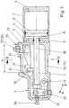
- the reference numeral 1 designates a clamping head on which axially one Cylinder 2 connects.
- the cylinder 2 is facing the clamping head 1 End through a cover 3 and on its opposite end face a bottom cover 4 delimited pressure-tight.
- a piston 6 is longitudinally displaceable in the cylinder 2 via a seal 5 guided longitudinally and sealingly, which is connected to a piston rod 7 is.
- the piston rod 7 passes through a bore 8 in the cover 3 and is sealed with a seal 9 fluid-tight.
- the piston rod 7 passes axially through the clamping head 1 and is at its end connected to a toggle joint assembly 10, which is an unspecified Clamp arm is assigned.
- the tension arm is in direction A or B pivotable about a certain opening angle about an axis 11 fixed to the housing arranged in the clamping head 1.
- the opening angle can be obtuse be.
- the chuck 1 has a housing that in the illustrated embodiment consists of two shell-shaped housing parts 12 and 13 (FIG. 2), which lie on top of each other in a sandwich-like and gap-free manner and thus the piston rod 7, the toggle joint assembly 10 and all other between the Housing parts 12 and 13 objects are dirt and moisture proof encapsulate.
- the housing parts 12 and 13 are through a straight dividing plane 14 (Fig. 2) separated from each other, so that the housing parts 12 and 13 flat through walls 15 and 16, respectively, and by screws (not referred to) are releasably connected. If necessary, can the walls may also be assigned sealing elements (not shown).
- the housing parts 12 and 13 are closed on all sides and have only on one side each have an approximately semicircular recess (not shown), which thus complement each other through a bore through which the piston rod 7 in the space 17 delimited by the housing parts 12 and 13 protrudes.
- the toggle joint arrangement 10 is also arranged in this space 17. The end of the piston rod 7 located within the space 17 and the toggle joint arrangement 10 are thus dirt, dust and spray liquid tight encapsulated to the outside.
- the two shell-shaped housing parts 12 and 13 each have an orthogonally penetrating bore (not shown) through which the axis 11 passes. Instead, the Axis 11 but also in non-penetrating formations of the relevant housing part 12 or 13 may be mounted.
- the two shell-shaped housing parts 12 and 13 guide grooves (not shown) on.
- the guide grooves can be of the same design and with each other in the assembled state, the housing parts 12 and 13 correspond, such that the toggle joint assembly 10 with associated components in Longitudinal axis direction is performed.
- the housing parts 12 and 13 holes for screws, not shown, by means of which the housing parts 12 and 13 can be screwed together in a joint-tight manner.
- the holes of a housing part as through holes be formed while the associated coaxially arranged thereto Holes of the other housing part are blind holes with thread.
- By screwing in bolts can be the housing parts 12 and 13 releasably, but tightly connect.
- the Housing parts 12 and 13 can be made of steel or aluminum or another suitable workpiece, for example also from an injection molding material, consist.
- the walls 15, 16 can be of high quality at the parting plane 14 trained, for example ground or with appropriate surface quality be poured so that they are full and tight on one another.
- the toggle joint arrangement 10 can be assigned fork arms (not shown) be with their ends square or polygonal in cross section designed end portions of the axis 11 are arranged. For this may be provided a tab that against the fork-shaped end of the assigned fork arm attacks and with formally adapted recesses engages around the end sections of the pivot pin and with the relevant one Fork arm is connected by screws (also not shown).
- the housing of the clamping head 1 is in an orthogonal to the longitudinal axis 18 of the piston rod 7 cross section rectangular educated.
- this means that the housing can be namely on the opposite sides of the rectangle either on device parts, for example in the body shop of the automotive industry, grown, for example screwed on.
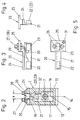
- Fig. 2 shows that in the area of one narrow side of the rectangular Basic shape of the housing, a slot 19 of width X is arranged is (Fig. 1) extends approximately over the length Y and in which a query cassette 20 is arranged.
- This query cassette 20 essentially consists from a guided in an orthogonal to the longitudinal axis 18 of the piston rod 7
- Cross-section L-shaped profile 21 which is designed as a mounting rail and has two spaced switches 22 and 23, respectively
- Microswitches, inductive switches, limit switches or pneumatic switches can be and adjustable in the longitudinal axis direction of the L-profile 21 and are arranged lockable, depending on the desired operating conditions.
- switches 22 and 23 are parallel to the Parting plane 14 extending web of the L-profile 21 attached during this orthogonal transverse web 24 is arranged in the slot 19 and seals it as joint-tight as possible to the outside and thus space 17 also closes to the outside here.
- the crossbar 24 extends over the Length Y (FIG. 1) of the slot 19.
- a flange 25 is suitably made in one piece with the L-shaped profile 21 connected, the present two through holes 26 (Fig. 5) for arrangement of the feeders 27 and 28 for electrical cables 29 and 30, respectively are connected to switches 22 and 23.
- the flange 25 a through hole 31 through which a screw, not shown reaches through, by means of which the query cassette 20 on the clamping head 1 can be exchanged is attached.
- a switching flag 32 is connected to the piston rod 7, which is arranged with a gap distance to the switches 22 and 23 and at damped the reciprocation of the piston rod 7 and thereby switching functions triggers.
- the query cassette 20 with the L-shaped profile 21 within the contours of the housing comes to lie so that it does not interfere with the outside. Only the feeders 27 and 28 protrude above the projection.
- the flange 25 is also on the outside arranged the housing 1. However, this also gives the opportunity to side of the toggle clamp device, i.e. from the back to install any device parts.
- the reference numeral 34 denotes an adjusting screw, which is also is accessible from the outside. Assembling a toggle clamp of the shown construction namely requires a precise procedure to ensure that the clamping force after setting up the clamping arm too is actually guaranteed. To achieve this, the adjusting screw 34 when leaving the manufacturing plant down to the block, i.e. fully screwed in. Due to this screw position, the tab of the toggle joint arrangement is located 10 at an angle of about 12 degrees. Now that Pressure piece was attached to the clamping arm, which later on the workpiece acts, the adjusting screw 34 is unscrewed to a further end stop. The toggle clamp device can now by the appropriate Pressurizing the piston 6 to the dead center position be driven, i.e. apply their maximum resilience.
- the toggle lever clamping device from its dead center position can be easily solved to manually open or retract the To enable Spanners.
- the adjustment screw 34 is also used for setting up of the clamping arm and for achieving the clamping force.
Landscapes
- Engineering & Computer Science (AREA)
- Mechanical Engineering (AREA)
- Jigs For Machine Tools (AREA)
- Clamps And Clips (AREA)
- A Measuring Device Byusing Mechanical Method (AREA)
- Mechanical Control Devices (AREA)
Description
Die Erfindung betrifft eine Kniehebelspannvorrichtung für den Karosseriebau
mit einem in einem orthogonal zur Längsachse der Kolbenstange geführten
Querschnitt rechteckförmigen Spannkopf, der aus zwei Gehäuseteilen aufgebaut
ist, und mit einem sich in axialer Verlängerung an das zylinderseitige Ende
des Spannkopfes anschließenden Zylinder, in dem ein abwechselnd beidseitig
durch Druckmitteldruck, insbesondere durch Luftdruck zu beaufschlagender
Kolben längsverschieblich und dichtend geführt ist, der mit seiner Kolbenstange
den Zylinder und einen Hohlraum des Spannkopfes axial durchgreift, wobei am
freien Ende der Kolbenstange eine Kniehebelgelenkanordnung befestigt ist, die
mit einem Spannarm gekoppelt ist, mit Endschaltern bzw. Stellungsgebern in
Form von Mikroschaltern, induktiven Schaltern, Pneumatikschaltern oder
Sensoren, die in einem Raum des Spannkopfes integriert sind, wobei die
Schalter relativ zueinander einstellbar sind und an einer die Abdeckung für
dieselben bildenden Halterung als insgesamt austauschfähige Abfragekassette
in Form einer Platine im Bereich eines Schlitzes
in axialer Richtung des Spannkopfes angeordnet und befestigt sind, wobei die
Abfragekassette in der Draufsicht eine ![]()
![]()
Eine derartige Kniehebelspannvorrichtung gemäß dem Oberbegriff des unabhängigen Anspruchs 1
bildet Gegenstand der auf die Anmelderin
zurückgehenden DE 93 11 132.0 U1 und der inhaltsgleichen europäischen
Patentanmeldung 0 636 449 (94 105 296.1-2302). Bei der Ausführungsform
nach Fig. 1 ist kein Schlitz vorgesehen, während bei der Ausführungsform
nach Fig. 8 die Kassette von der Seite her angebaut wird.Such a toggle lever tensioning device according to the preamble of
Aus der DE 92 15 151.5 U1 ist eine Spannvorrichtung zum Festspannen von Werkstücken vorbekannt, bestehend aus einem gabelförmigen Kopfstück, an dem der Spannarm schwenkbar gelagert ist, der mit dem Ende einer bewegbaren Stellstange des Vorrichtungsantriebes in Verbindung steht, wobei im Stell-wegsbereich des Endes der Stellstange neben dieser Endstellungsabfrageschalter angeordnet sind und am Ende der Stellstange der Lagerzapfen für Führungsrollen der Stellstange verlängert ist und den Stellungsgeber bildet, der in ein sich parallel zur Stellstange erstreckendes Langloch in den Anordnungsbereich der Endstellungsfühler einragt, wobei das Kopfstück an einer Außenflanke eines seiner Gabelteile mit einer flachen, gegen den Stellwegsbereich des Endes der Stellstange und nach außen offenen Ausnehmungen versehen ist, wobei in der nach außen offenen Ausnehmung der mindestens eine mit zwei Endstellungsfühlern versehenen Endstellungsabfrageschalter angeordnet ist und die Ausnehmung mit dem darin angeordneten Endstellungsabfrageschalter mit einem lösbar am Kopfstück angeordneten Abdeckblech verschlossen ist.DE 92 15 151.5 U1 describes a tensioning device for tightening Known workpieces, consisting of a fork-shaped head piece which the clamping arm is pivotally mounted, the end of a movable Control rod of the device drive is connected, in the range of travel the end of the control rod next to this limit switch are arranged and at the end of the adjusting rod of the bearing pin for Guide rollers of the actuating rod is extended and forms the position transmitter that in an elongated hole extending parallel to the control rod in the arrangement area the end position sensor protrudes, the head piece on an outer flank one of his fork parts with a flat, against the travel range of the end of the adjusting rod and recesses open to the outside is, the at least one with in the recess open to the outside two end position sensors provided end position interrogation switch and the recess with the end position interrogation switch arranged therein closed with a cover plate detachably arranged on the head piece is.
Letztere Bauart benötigt umständlicherweise anzufertigende Hohlräume, in denen die Schalter anzuordnen sind und die Anpassung von besonderen Abdeckblechen. Bei Störungen muß zunächst das Abdeckblech entfernt und die in den Hohlräumen montierten Schalter gelöst und ausgetauscht werden. Die Anordnung dieser speziellen Hohlräume ist kostenträchtig, wobei auch das Austauschen defekter Schalter und deren Montage sehr zeitaufwendig ist.The latter type requires awkward cavities in which the switches are to be arranged and the adaptation of special cover plates. In the event of malfunctions, the cover plate must first be removed and the in the switches mounted in the cavities can be loosened and replaced. The order of these special cavities is costly, as well as replacing them defective switches and their assembly is very time consuming.
Aus dem DE-U-90 16 781.3 ist eine Spannvorrichtung mit Verstellaggregat, Spannarm, Endstellungsabfrageeinrichtungen und Antriebsstellstange, mit der der Spannarm direkt oder indirekt zwischen von den Endstellungsabfrageelementen vorgegebenen Endstellungen verschwenkbar ist, vorbekannt. Die Endstellungsabfrageelemente sind in einem separaten, mit der Spannvorrichtung lösbar verbundenen Gehäuse neben einer in diesem Gehäuse achsial geführten und verstellbaren, mit Stellungsgeber versehenen Fühlerstange angeordnet, die sich parallel zu einer Gehäuseanschlußfläche erstreckt und mit ihrem oberen Ende aus dem Gehäuse herausragt, zwischen dem und der Stellungsstange eine mit dem oberen Ende und der Stellstange achsial fixierte Mitnehmertraverse angeordnet ist. Die Endstellungsabfrageelemente sind in dem Gehäuse in Bezug auf den Stellungsgeber einstellbar angeordnet. Diese Spannvorrichtung ist mit einem Spannarm in einem am Antriebsaggregat angeordneten gabelartigen Kopfstück schwenkbar gelagert. Das Gehäuse ist auf der Spannarmseite oder der spannarmfernen Seite der Vorrichtung mit seiner Gehäuseanschlußfläche angeordnet, wobei sich die Mitnehmertraverse von der Führungsstange zwischen den Gabelteilen des Kopfstückes zur Stellstange erstreckt. Mindestens in einem Gabelteil des Kopfstückes ist seitlich und parallel zur Stellstange ein Längsschlitz und an der Längsschlitzseite der Vorrichtung das Gehäuse angeordnet, wobei die sich zwischen dem oberen Ende der Fühlerstange und der Stellstange erstreckende Mitnehmertraverse sich durch den Längsschlitz erstreckt. Die Stellstange ist mit dem Spannarm vom Antriebsaggregat gleichzeitig drehend und in Achsrichtung bewegbar. Das Gehäuse ist auf einer der beiden schwenkbereichsfernen Seiten der Vorrichtung angeordnet, wobei die Mitnehmertraverse mit der Stellstange und/oder dem Spannarm drehbar verbunden ist. Das stellstangenseitige Anschlußende der Mitnehmertraverse ist gabelartig ausgebildet.DE-U-90 16 781.3 describes a tensioning device with an adjusting unit, Tension arm, end position interrogation devices and actuator stem with which the tension arm directly or indirectly between the end position sensing elements predetermined end positions is pivotable, previously known. The End position query elements are in a separate, with the clamping device Detachably connected housing in addition to an axial in this housing guided and adjustable sensor rod provided with position transmitter, which extends parallel to a housing connection surface and with its upper end protrudes from the housing, between the and the Position rod one with the upper end and the control rod axially fixed Driver crossbar is arranged. The end position query elements are in the housing is arranged adjustable in relation to the position transmitter. This Clamping device is arranged with a clamping arm in a on the drive unit fork-like head piece pivotally mounted. The case is on the Clamping arm side or the side of the device remote from the clamping arm with its housing connection surface arranged, the entrainer from the Guide rod between the fork parts of the head piece to the control rod extends. At least in one fork part of the head piece is laterally and parallel to the control rod a longitudinal slot and on the longitudinal slot side of the device arranged the housing, which is between the upper end of the Sensor rod and the actuator cross bar extending through extends the longitudinal slot. The control rod is with the tension arm from the drive unit simultaneously rotating and movable in the axial direction. The housing is arranged on one of the two sides of the device remote from the swivel range, the driver crossbar with the adjusting rod and / or the tension arm is rotatably connected. The connecting rod end of the driver crossbar on the rod side is fork-shaped.
Aus der DE 30 22 376 C2 ist eine Kniehebelspannvorrichtung zum Festspannen von Werkstücken, insbesondere Karosserieteilen, bestehend aus einem Druckzylinder mit doppelt wirksamem Kolben und Kolbenstange, vorbekannt, deren Ende mit einem Kopfstück versehen ist, das in einem an dem Zylinder axial angesetzten Führungsstück geführt und über ein angelenktes Zwischenglied beweglich mit einem am Führungsstück an einem seitlichen Schwenkgelenk gelagerten Spannhebel verbunden sowie über eine Flachführung am Führungsstück abgestützt ist, wobei diese Flachführung in einer Ebene liegt, die parallel zur einer durch die Kolbenstangenachse gelegten Ebene und auf der zum Schwenkgelenk des Spannhebels abgewandten Seite angeordnet ist. Die Flachführung ist an einer dem Schwenkgelenk gegenüberliegenden, maximal von der Kolbenstangenachse entfernten Innenfläche des Führungsstückes angeordnet. Am freien Ende des Führungsstückes ist ein Hubbegrenzungsstellelement in der Nähe der Flachführung angeordnet.DE 30 22 376 C2 describes a toggle lever clamping device for clamping of workpieces, in particular body parts, consisting of a Pressure cylinder with double-acting piston and piston rod, previously known, the end of which is provided with a head piece which is in one on the cylinder guided axially attached guide piece and a hinged intermediate member movable with one on the guide piece on one side Swivel-mounted tension lever connected and via a flat guide is supported on the guide piece, this flat guide in one Plane is parallel to the one through the piston rod axis Level and on the side facing away from the swivel joint of the tensioning lever is arranged. The flat guide is on a maximum inner surface of the piston rod axis Guide piece arranged. At the free end of the guide piece is a Stroke control element arranged near the flat guide.
Der Erfindung liegt die Aufgabe zugrunde, eine Kniehebelspannvorrichtung der im Gattungsbegriff vorausgesetzten Art dahingehend auszubilden, daß sie nicht nur von der Rückseite, sondern auch von allen vier Seiten an Vorrichtungsteilen anbaubar ist, unter Beibehaltung der von der Kassettentechnik her bekannten Vorteile.The invention has for its object a toggle lever device in the genre-presupposed kind in such a way that they do not only from the back, but also from all four sides of device parts can be added while maintaining the well-known cassette technology Advantages.
Diese Aufgabe wird durch die in Patentanspruch 1 wiedergegebenen Merkmale
gelöst.This object is achieved by the features set out in
Bei der erfindungsgemäßen Spannvorrichtung wird die Abfragekassette von der Rückseite des Spannergehäuses durch eine enge, schlitzförmige Ausnehmung in das Gehäuse eingesteckt. Die Abfragekassette ist demzufolge nur schmal gestaltet und beinhaltet die Sensoren, die Stecker, die miteinander verkabelt sind und etwaige Befestigungsmuttern bzw. Schrauben. Obwohl die Abfragekassette von der Rückseite in eine schlitzförmige Ausnehmung des Gehäuses eingeführt wird, kann die dort befindliche Anbaumöglichkeit voll genutzt, das heißt, die Kniehebelspannvorrichtung auch von dieser Seite angebaut werden. Die Kniehebelspannvorrichtung kann somit auch von der Rückseite befestigt werden bzw. es können dort befindliche Konsolen, Halterungen usw. angeschraubt werden. Auch bei der Erfindung werden etwaige Endschalter, Mikroschalter, induktive Schalter, Sensoren oder dergleichen verstellbar angeordnet, um verschiedene Öffnungswinkel, Hübe oder dergleichen einzustellen. Diese Kassettentechnik ist sehr servicefreundlich, da durch Lösen von zum Beispiel nur einer Schraube die komplette Abfragekassette mit Schalter und Steckern, die in sich komplett verkabelt sind, auszuwechseln ist. Am Lager können somit komplett austauschfähige Abfragekassetten bereitgehalten werden, die sich mit wenigen Handgriffen austauschen lassen. Dadurch sind nur geringe Stillstandszeiten zu erwarten, sollte es erforderlich sein, die Abfragekassette auszutauschen. In the tensioning device according to the invention, the query cassette is removed from the Back of the tensioner housing through a narrow, slit-shaped recess inserted into the housing. As a result, the query cassette is only narrow designed and includes the sensors, the plugs that are wired together and any fastening nuts or screws. Although the query cassette from the back into a slot-shaped recess in the housing is introduced, the cultivation option located there can be fully used means that the toggle clamp device can also be attached from this side. The toggle lever tensioning device can thus also be attached from the rear or consoles, brackets etc. located there can be screwed on become. Any limit switches, microswitches, adjustable inductive switches, sensors or the like, to set different opening angles, strokes or the like. This Cassette technology is very easy to service, because by loosening, for example the complete query cassette with switches and plugs with just one screw, which are completely wired in themselves, must be replaced. So in stock Completely interchangeable query cassettes are kept ready can be replaced in a few simple steps. This means there are only short downtimes expected, it should be necessary to replace the query cassette.
In Patentanspruch 2 ist eine bevorzugte Ausführungsform der Erfindung beschrieben.
Bei dieser Ausführungsform weist die Abfragekassette eine in einem
orthogonal zur Längsachse der Kolbenstange geführten Schnitt etwa L-förmige
Gestalt auf, an der endseitig ein sich orthogonal zur Längsachse des
Gemäß Patentanspruch 3 erstreckt sich die Schiene der Abfragekassette in
Längsachsrichtung der Kolbenstange, verläuft also parallel zu dieser. An dieser
Schiene sind die Endschalter, Mikroschalter, induktive Schalter bzw. Sensoren
lageveränderlich angeordnet und werden von einer der Kolbenstange zugeordneten
Schaltfahne bedämpft, das heißt beim Verschieben der Kolbenstange
überstrichen und lösen dadurch die verschiedenen Folgesteuerungen aus.According to
Patentanspruch 4 beschreibt eine weitere vorteilhafte Ausführungsform der
Erfindung.
Das Montieren einer Kniehebelspannvorrichtung in einer Vorrichtung, zum Beispiel für den Karosseriebau der Kfz-Industrie, erfordert eine genaue Vorgehensweise um sicherzustellen, daß die Spannkraft nach dem Einrichten des Spannarmes auch gewährleistet ist. Um dies zu erreichen, wird erfindungsgemäß eine Schraube im Anlieferungszustand der Kniehebelspannvorrichtung bis auf Block eingeschraubt. Durch diese Schraubstellung befindet sich die Lasche der Kniehebelspannvorrichtung in einem Winkel von etwa 12 Grad. Nachdem nun das Druckstück am Spannarm angebracht worden ist, wird diese Schraube herausgeschraubt, und zwar bis zum Endanschlag. Daraufhin kann die Kniehebelspannvorrichtung durch Druckmitteldruck, zum Beispiel durch Pneumatikdruck, in Übertotpunktlage gefahren werden, wodurch die volle Spannkraft aufgebracht wird. Mit der Schraube kann durch Einschrauben die Kniehebelspannvorrichtung allerdings im Bedarfsfalle auch aus dieser Übertotpunktlage gelöst werden, um ein manuelles Öffnen bzw. Zurückfahren der Kniehebelspannvorrichtung zu ermöglichen. Die Schraube dient somit zum Einrichten der Spannvorrichtung und für die Erzielung der Spannkraft sowie ebenso zum Lösen der Kniehebelspannvorrichtung aus der Totpunkt- bzw. Übertotpunktlage (Patentanspruch 5). The assembly of a toggle lever clamping device in a device, for example for the body shop of the motor vehicle industry, requires a precise procedure to ensure that the clamping force is also guaranteed after the clamping arm has been set up. In order to achieve this, according to the invention, a screw is screwed in except for the block in the delivery state of the toggle lever tensioning device. Due to this screw position, the tab of the toggle lever tensioning device is at an angle of approximately 12 degrees. Now that the pressure piece has been attached to the clamping arm, this screw is unscrewed, up to the end stop. The toggle lever clamping device can then be moved to the dead center position by pressure medium pressure, for example by pneumatic pressure, as a result of which the full clamping force is applied. With the screw, however, the toggle lever tensioning device can also be released from this over-dead center position by screwing in, if necessary, in order to enable manual opening or retraction of the toggle lever tensioning device. The screw thus serves to set up the tensioning device and to achieve the tensioning force and also to release the toggle lever tensioning device from the dead center or over dead center position ( claim 5 ).
Bei der Ausführungsform nach Patentanspruch 6 ist ein Gewindestopfen vorgesehen,
der als weiterer Endanschlag des Kniehebelgelenkes eingestellt wird.
In der Endstellung, also wenn die Kniehebelspannvorrichtung geschlossen ist,
was gleichzeitig in der Regel der Übertotpunktlage entspricht, fährt das Kniehebelgelenk
gegen einen Anschlag, vorliegend gegen einen Gewindestopfen, um
dadurch den Spannarm in eine spielfreie und absolut feststehende Position zu
bringen. Der Gewindestopfen ist von außen verstellbar und somit montagefreundlich,
um etwaige Toleranzen der Gelenkteile ausgleichen zu können.In the embodiment according to
In der Zeichnung ist die Erfindung - teils schematisch - beispielsweise veranschaulicht. Es zeigen:
- Fig. 1
- eine Kniehebelspannvorrichtung, insbesondere für den Karosseriebau, im Axiallängsschnitt;
- Fig. 2
- einen Querschnitt nach der Linie II - II der Fig. 1;
- Fig. 3
- eine Abfragekassette in der Seitenansicht;
- Fig. 4
- eine linke Stirnansicht zu Fig. 3 und
- Fig. 5
- eine Draufsicht zur Fig. 3.
- Fig. 1
- a toggle lever tensioning device, in particular for body construction, in axial longitudinal section;
- Fig. 2
- a cross section along the line II - II of Fig. 1;
- Fig. 3
- a query cassette in side view;
- Fig. 4
- a left front view of Fig. 3 and
- Fig. 5
- 3 shows a top view of FIG. 3.
Mit dem Bezugszeichen 1 ist ein Spannkopf bezeichnet, an dem sich axial ein
Zylinder 2 anschließt. Der Zylinder 2 ist an dem dem Spannkopf 1 zugekehrten
Ende durch einen Deckel 3 und an seiner entgegengesetzten Stirnseite durch
einen Bodendeckel 4 druckmitteldicht abgegrenzt.The
In dem Zylinder 2 ist längsverschieblich über eine Dichtung 5 ein Kolben 6
längsverschieblich und dichtend geführt, der mit einer Kolbenstange 7 verbunden
ist. Die Kolbenstange 7 durchgreift eine Bohrung 8 in dem Deckel 3 und ist
mit einer Dichtung 9 druckmitteldicht abgedichtet.A
Die Kolbenstange 7 durchgreift axial den Spannkopf 1 und ist an ihrem Ende
mit einer Kniehebelgelenkanordnung 10 verbunden, der ein nicht näher bezeichneter
Spannarm zugeordnet ist. Der Spannarm ist in Richtung A bzw. B
um einen gewissen Öffnungswinkel um eine gehäusefeste Achse 11 schwenkbeweglich
im Spannkopf 1 angeordnet. Der Öffnungswinkel kann stumpfwinklig
sein. The
Der Spannkopf 1 weist ein Gehäuse auf, das bei der dargestellten Ausführungsform
aus zwei schalenförmigen Gehäuseteilen 12 bzw. 13 (Fig. 2) besteht,
die sandwichartig und spaltfrei aufeinanderliegen und damit die Kolbenstange
7, die Kniehebelgelenkanordnung 10 und alle sonstigen zwischen den
Gehäuseteilen 12 und 13 befindlichen Gegenstände schmutz- und feuchtigkeitsdicht
kapseln.The
Die Gehäuseteile 12 und 13 sind durch eine geradlinig verlaufende Trennebene
14 (Fig. 2) voneinander getrennt, so daß die Gehäuseteile 12 und 13 flächig
durch Wandungen 15 bzw. 16 aufeinanderliegen und durch Schrauben (nicht
näher bezeichnet) lösbar miteinander verbunden sind. Im Bedarfsfalle können
den Wandungen auch noch Dichtungselemente zugeordnet sein (nicht dargestellt).The
Die Gehäuseteile 12 und 13 sind allseitig geschlossen ausgebildet und weisen
lediglich an ihrer einen Seite je eine etwa halbkreisförmige Aussparung auf
(nicht dargestellt), die sich somit zu einer Bohrung ergänzen, durch die die Kolbenstange
7 in den durch die Gehäuseteile 12 und 13 begrenzten Raum 17
hineinragt. In diesem Raum 17 ist auch die Kniehebelgelenkanordnung 10 angeordnet.
Das innerhalb des Raumes 17 liegende Ende der Kolbenstange 7
und die Kniehebelgelenkanordnung 10 sind damit schmutz-, staub- und spritzflüssigkeitsdicht
nach außen hin abgekapselt. Die beiden schalenförmigen Gehäuseteile
12 und 13 weisen je eine sie orthogonal durchsetzende Bohrung auf
(nicht dargestellt), durch die die Achse 11 hindurchgreitt. Statt dessen kann die
Achse 11 aber auch in nach außen nicht hindurchdringende Ausformungen des
betreffenden Gehäuseteils 12 bzw. 13 gelagert sein. Des weiteren weisen die
beiden schalenförmigen Gehäuseteile 12 und 13 Führungsnuten (nicht dargestellt)
auf. Die Führungsnuten können gleich ausgebildet sein und miteinander
im zusammengebauten Zustand die Gehäuseteile 12 und 13 korrespondieren,
derart, daß die Kniehebelgelenkanordnung 10 mit zugeordneten Bauteilen in
Längsachsrichtung geführt wird. Des weiteren weisen die Gehäuseteile 12 und
13 Bohrungen für nicht dargestellte Schrauben auf, mittels deren die Gehäuseteile
12 und 13 miteinander fugendicht verschraubt werden können. Zum Beispiel
können die Bohrungen eines Gehäuseteils als Durchgangsbohrungen
ausgebildet sein, während dann die zugeordneten koaxial hierzu angeordneten
Bohrungen des anderen Gehäuseteils Sackbohrungen mit Gewinde sind.
Durch Einschrauben von nicht dargestellten Schraubenbolzen lassen sich dadurch
die Gehäuseteile 12 und 13 lösbar, aber dicht miteinander verbinden. Die
Gehäuseteile 12 und 13 können aus Stahl oder Aluminium oder aus einem anderen
geeigneten Werkstück, zum Beispiel auch aus einem Spritzgußmaterial,
bestehen. Die Wandungen 15, 16 können an der Trennebene 14 hochwertig
ausgebildet, zum Beispiel geschliffen oder mit entsprechender Oberflächengüte
gegossen sein, so daß sie satt und fugendicht aufeinanderliegen.The
Der Kniehebelgelenkanordnung 10 können Gabelarme (nicht dargestellt) zugeordnet
sein, die mit ihren Enden auf im Querschnitt quadratischen oder polygonförmig
gestalteten Endabschnitten der Achse 11 angeordnet sind. Hierzu
kann eine Haltelasche vorgesehen sein, die gegen das gabelförmige Ende des
zugeordneten Gabelarmes angreift und mit formmäßig angepaßten Ausnehmungen
die Endabschnitte des Schwenkbolzens umgreift und mit dem betreffenden
Gabelarm durch Schrauben verbunden ist (gleichfalls nicht dargestellt).The toggle
Es kann dem Gabelarm außerdem ein Anschraubteil zugeordnet sein, das zentrisch oder exzentrisch in bezug auf den Gabelarm angeordnet ist.It can also be assigned a screw-on part of the fork arm is arranged centrically or eccentrically with respect to the fork arm.
Wie man aus Fig. 2 erkennt, ist das Gehäuse des Spannkopfes 1 in einem orthogonal
zur Längsachse 18 der Kolbenstange 7 geführten Querschnitt rechteckförmig
ausgebildet. Dadurch kann das Gehäuse prinzipiell an vier Seiten,
nämlich an den jeweils gegenüberliegenden Rechteckseiten wahlweise an Vorrichtungsteilen,
zum Beispiel im Karosseriebau der Kfz-Industrie, angebaut,
zum Beispiel angeschraubt werden.As can be seen from Fig. 2, the housing of the clamping
Die Fig. 2 läßt erkennen, daß im Bereich der einen Schmalseite der rechteckförmigen
Grundgestalt des Gehäuses ein Schlitz 19 der Breite X angeordnet
ist, der sich (Fig. 1) etwa über die Länge Y erstreckt und in dem eine Abfragekassette
20 angeordnet ist. Diese Abfragekassette 20 besteht im wesentlichen
aus einem in einem orthogonal zur Längsachse 18 der Kolbenstange 7 geführten
Querschnitt L-förmigen Profil 21, das als Anbauschiene ausgebildet ist und
zwei mit Abstand zueinander angeordnete Schalter 22 bzw. 23 aufweist, die als
Mikroschalter, induktive Schalter, Endschalter oder Pneumatikschalter ausgebildet
sein können und die in Längsachsrichtung des L-Profils 21 verstellbar
und arretierbar angeordnet sind, je nach den gewünschten Betriebsverhältnissen.
Wie man erkennt, sind diese Schalter 22 und 23 an dem parallel zur
Trennebene 14 verlaufenden Steg des L-Profils 21 befestigt, während der dazu
orthogonal verlaufende Quersteg 24 in dem Schlitz 19 angeordnet ist und
diesen nach außen hin möglichst fugendicht abdichtet und damit den Raum 17
auch hier nach außen hin verschließt. Der Quersteg 24 erstreckt sich über die
Länge Y (Fig. 1) des Schlitzes 19. Fig. 2 shows that in the area of one narrow side of the rectangular
Basic shape of the housing, a
Mit dem L-förmigen Profil 21 ist ein Flansch 25 in geeigneter Weise einstückig
verbunden, der vorliegend zwei Durchgangsbohrungen 26 (Fig. 5) zum Anordnen
der Zuführungen 27 bzw. 28 für elektrische Kabel 29 bzw. 30 aufweist, die
mit den Schaltern 22 und 23 verbunden sind. Außerdem weist der Flansch 25
eine Durchgangsbohrung 31 auf, durch die eine nicht dargestellte Schraube
hindurchgreift, mittels derer die Abfragekassette 20 an dem Spannkopf 1 auswechselbar
befestigt ist. Es können auch mehrere Bohrungen und damit mehrere
Schrauben vorgesehen sein (nicht dargestellt).A
Wie man erkennt, ist mit der Kolbenstange 7 eine Schaltfahne 32 verbunden,
die mit Spaltabstand zu den Schaltern 22 und 23 angeordnet ist und diese bei
der Hin- und Herbewegung der Kolbenstange 7 bedämpft und dadurch Schaltfunktionen
auslöst. Deutlich ist aus Fig. 1 zu erkennen, daß die Abfragekassette
20 mit dem L-förmigen Profil 21 innerhalb der Konturen des Gehäuses zu
liegen kommt, so daß sie nach außen nicht stört. Lediglich die Zuführungen 27
und 28 ragen über die Projektion hervor. Auch ist der Flansch 25 außen an
dem Gehäuse 1 angeordnet. Dadurch besteht aber die Möglichkeit, auch an
dieser Seite die Kniehebelspannvorrichtung, also von der Rückseite her, an
irgendwelchen Vorrichtungsteilen anzubauen. Selbstverständlich kann dies
auch an der gegenüberliegenden Seite und an den beiden gegenüberliegenden
Längsseiten des im Querschnitt rechteckförmigen Gehäuses geschehen, so
daß die Kniehebelspannvorrichtung wahlweise von vier Seiten angebaut und
damit befestigt werden kann. Bei der Erfindung wird somit die Abfragekassette
20 von der Rückseite des Gehäuses in den Schlitz 19 hineingesteckt und befestigt
und stört dadurch in keiner Weise, so daß die Kniehebelspannvorrichtung
- wie erwähnt - auch von dieser Rückseite befestigt werden kann. Die
Kassettentechnik ist dadurch servicefreundlich, da durch Lösen von nur einer
Schraube die komplette Abfragekassette 20 mit Schaltern und Steckern, in sich
komplett verkabelt, ausgewechselt werden kann.As can be seen, a switching
Mit dem Gewindestopfen 33 wird der Endanschlag der Kniehebelgelenkanordnung
10 eingestellt. In der Endstellung, also wenn der Spanner geschlossen
und gleichzeitig in Übertotpunktstellung gefahren ist, fährt die Kniehebelgelenkanordnung
10 gegen den Gewindestopfen 33, um dadurch den Spannarm in
eine spielfreie und absolut feststehende Position zu bringen. Wie man erkennt,
ist dieser Gewindestopfen 33 von außen verstellbar und somit montage- und
servicefreundlich, um Toleranzen in den Gelenkteilen der Kniehebelgelenkanordnung
10 ausgleichen zu können. With the threaded
Mit dem Bezugszeichen 34 ist eine Einstellschraube bezeichnet, die ebenfalls
von außen zugänglich ist. Das Montieren einer Kniehebelspannvorrichtung der
dargestellten Bauweise erfordert nämlich eine genaue Vorgehensweise, um
sicherzustellen, daß die Spannkraft nach dem Einrichten des Spannarms auch
tatsächlich gewährleistet ist. Um dies zu erreichen, wird die Einstellschraube 34
beim Verlassen des Herstellerwerkes bis auf Block, also vollständig eingeschraubt.
Durch diese Schraubstellung befindet sich die Lasche der Kniehebelgelenkanordnung
10 in einem Winkel von etwa 12 Grad. Nachdem nun das
Druckstück am Spannarm angebracht wurde, das später auf das Werkstück
einwirkt, wird die Einstellschraube 34 bis zu einem weiteren Endanschlag herausgeschraubt.
Die Kniehebelspannvorrichtung kann nun durch die entsprechende
Druckmittelbeaufschlagung des Kolbens 6 in die Übertotpunktlage
gefahren werden, das heißt ihre maximale Spannkraft aufbringen. Mit der Einstellschraube
34 kann, zum Beispiel bei Energieverlust, durch Einschrauben
der Einstellschraube 34 die Kniehebelspannvorrichtung aus ihrer Übertotpunktlage
leicht gelöst werden, um ein manuelles Öffnen bzw. Zurückfahren des
Spanners zu ermöglichen. Die Einstellschraube 34 dient auch zum Einrichten
des Spannarmes und für die Erzielung der Spannkraft. The
Die in der Zusammenfassung, in den Patentansprüchen und in der Beschreibung beschriebenen sowie aus der Zeichnung ersichtlichen Merkmale können sowohl einzeln als auch in beliebigen Kombinationen für die Verwirklichung der Erfindung wesentlich sein. The in the summary, in the claims and in the description described features and can be seen from the drawing both individually and in any combination for the realization of the Invention to be essential.
Prospekt der Firma ISI Automation Anlagen- und Komponenten Vertriebs
GmbH -
Prospekt der Firma ISI Manufacturing Inc.
Prospektblätter KG84A32101, KG84A32102, KG84A32103, KG84A32104 der
Firma DE-STA-CO Metallerzeugnisse GmbH betreffend
Prospekt der Firma Sommer Automatic GmbH
Prospektblatt der Firma Fritz Schunk GmbH
Prospektblatt der Firma Fritz Schunk GmbH
Katalog
- 11
- SpannkopfClamping head
- 22nd
- Zylindercylinder
- 33rd
- Deckelcover
- 44th
- BodendeckelBottom cover
- 55
- Dichtungpoetry
- 66
- Kolbenpiston
- 77
- KolbenstangePiston rod
- 88th
- Bohrungdrilling
- 99
- Dichtungpoetry
- 1010th
- KniehebelgelenkanordnungToggle joint arrangement
- 1111
- Achse, gehäusefesteAxis, housing-fixed
- 1212th
- Gehäuseteil, schalenförmigesHousing part, bowl-shaped
- 1313
- Gehäuseteil, schalenförmigesHousing part, bowl-shaped
- 1414
- Trennebene, geradeDividing plane, straight
- 1515
- WandungWall
- 1616
- WandungWall
- 1717th
- Raumroom
- 1818th
- LängsachseLongitudinal axis
- 1919th
- Schlitzslot
- 2020th
- Abfragekassette Query cassette
- 2121
- Profil, L-förmigesProfile, L-shaped
- 2222
- Schalter, induktiver Schalter, Mikroschalter, Sensor, PneumatikschalterSwitches, inductive switches, microswitches, sensors, pneumatic switches
- 2323
- Schalter, induktiver Schalter, Mikroschalter, Sensor, PneumatikschalterSwitches, inductive switches, microswitches, sensors, pneumatic switches
- 2424th
- QuerstegCrossbar
- 2525th
- Flanschflange
- 2626
- DurchgangsbohrungThrough hole
- 2727
- ZuführungFeed
- 2828
- ZuführungFeed
- 2929
- Kabel, elektrischesCable, electrical
- 3030th
- Kabel, elektrischesCable, electrical
- 3131
- DurchgangsbohrungThrough hole
- 3232
- SchaltfahneSwitch flag
- 3333
- Gewindestopfen, Endanschlag, AnschlagThreaded plug, end stop, stop
- 3434
- Einstellschraube, EndanschlagAdjustment screw, end stop
- AA
- Schwenkrichtung des SpannarmsSwivel direction of the tension arm
- BB
- Schwenkrichtung des SpannarmsSwivel direction of the tension arm
- XX
-
Breite des Schlitzes 19Width of the
slot 19 - YY
-
Länge des Schlitzes 19Length of the
slot 19
Claims (6)
- A toggle clamp for car bodywork construction with a rectangular grip holder (1) having a cross-section guided orthogonally in relation to the longitudinal axis (18) of the piston rod (7), said grip holder (1) being constructed from two housing sections (12, 13) and guided with a cylinder (2) attaching in axial extension to the cylinder-side end of the grip holder (1), in which a piston (6) to be acted upon alternately on both sides by pressure medium pressure, especially air pressure, is guided in a longitudinally displaceable and sealing manner and reaches through the cylinder (2) and a hollow space of the grip holder (1) with its piston rod (7) in axial direction; a toggle joint arrangement (10) with a clamping arm coupled thereto being fixed at the free end of the piston rod (7), with limit switches and/or position indicators in the form of microswitches, inductive switches, pneumatic switches or sensors (22, 23) integrated within a space (17) of the grip holder (1); the switches (22, 23) being adjustable relative to one another and arranged and fixed to a mount forming the cover therefor as an altogether interchangeable interrogator cassette (20) in the form of a printed circuit in way of a slot (19) in axial direction of the grip holder (1); the interrogator cassette (20), in top plan view, being of T-shaped configuration and having an attachment rail and a flange (25) to which a section (21) extending with its longtiduinal axis in parallel with the longitudinal axis (18) of the piston rod is linked up; characterized in that the interrogator cassette (20) is plugged through a narrow slot (19) extending in the direction of the longitudinal axis (18) of the piston rod (7) from the rear of the housing of the grip holder (1) and, while maintaining the possibility of attachment of the toggle joint arrangement from all four sides, especially from the rear, in such a manner that the section (21) will seal the slot (19) towards the outside, preferably, joint-tight.
- Toggle clamp as claimed in Claim 1, characterized in that the section (21) is designed in L-shaped configuration in a cross-section guided orthogonally in relation to the longitudinal axis (18) of the piston rod (7), the land of the "L" extending in parallel with the longitudinal axis (18) of the piston rod (7) and the switches (22, 23) being adjustable, while the crossbar (24) closes the slot (19) towards the outside.
- Toggle clamp as claimed in Claims 1 or 2, with a grip holder (1) consisting of two dish-shaped housing sections (12, 13) lying flush on top of each other and encasing the toggle joint arrangement (10), the piston rod (7) and the limit switches (22, 23) in a dirt and dust proof manner towards the outside; characterized in that the two dish-shaped housing sections (12, 13) feature the slot (19) for arranging the interrogator cassette (20) on the one, i.e. the narrower side of the grip holder (1) of rectangular cross-section.
- Toggle clamp as claimed in Claims 2 or 3, characterized in that the section (21) plunges into the slot (19) to such an extent that the one, i.e. the narrower side of the grip holder (1) of rectangular cross-section surmounts the boundary of the L-shaped section (21) which is pointing towards the outside.
- Toggle clamp as claimed in Claim 4 with a limit stop (33) for the toggle joint arrangement (10), primarily in the above-dead-centre position of the toggle joint; characterized in that the limit stop (33) is designed as a stop which is adjustable in its longitudinal axis direction to be actuated from outside, especially as a screw cap (33).
- Toggle clamp as claimed in Claim 5, characterized in that a further adjustable limit stop (34) for manually releasing the toggle joint arrangement (10) from the above-dead-centre position is arranged on the front side of the grip holder (1).
Applications Claiming Priority (2)
| Application Number | Priority Date | Filing Date | Title |
|---|---|---|---|
| DE19616441A DE19616441C1 (en) | 1996-04-25 | 1996-04-25 | Toggle joint clamping device for vehicle bodywork, with grip head |
| DE19616441 | 1996-04-25 |
Publications (2)
| Publication Number | Publication Date |
|---|---|
| EP0803331A1 EP0803331A1 (en) | 1997-10-29 |
| EP0803331B1 true EP0803331B1 (en) | 1999-08-04 |
Family
ID=7792358
Family Applications (1)
| Application Number | Title | Priority Date | Filing Date |
|---|---|---|---|
| EP97104333A Expired - Lifetime EP0803331B1 (en) | 1996-04-25 | 1997-03-14 | Toggle clamp for car bodywork construction |
Country Status (4)
| Country | Link |
|---|---|
| US (1) | US5845897A (en) |
| EP (1) | EP0803331B1 (en) |
| DE (1) | DE19616441C1 (en) |
| ES (1) | ES2135962T3 (en) |
Cited By (1)
| Publication number | Priority date | Publication date | Assignee | Title |
|---|---|---|---|---|
| DE202014102804U1 (en) | 2014-05-22 | 2014-07-29 | Pepperl + Fuchs Gmbh | Encoder for power clamps |
Families Citing this family (66)
| Publication number | Priority date | Publication date | Assignee | Title |
|---|---|---|---|---|
| DE19702203A1 (en) * | 1997-01-23 | 1998-07-30 | Sta Co Mettallerzeugnisse Gmbh | Pneumatic end position interrogation device |
| DE19702204C1 (en) * | 1997-01-23 | 1998-04-23 | Sta Co Mettallerzeugnisse Gmbh | Pneumatic end position testing device |
| FR2769255B1 (en) * | 1997-10-08 | 1999-12-03 | Genus Technologie Ind | HOLDING, POSITIONING, OR TIGHTENING DEVICE |
| DE19751950C1 (en) * | 1997-11-24 | 1999-03-04 | Isi International Sa | Toggle actuated vehicle bodywork clamp |
| DE19801433A1 (en) * | 1998-01-16 | 1999-07-22 | Sta Co Mettallerzeugnisse Gmbh | Jig |
| DE19808631A1 (en) * | 1998-02-28 | 1999-09-02 | Sta Co Mettallerzeugnisse Gmbh | Jig |
| US6192284B1 (en) | 1998-05-15 | 2001-02-20 | Norgren Automotive, Inc. | Clamping arm position sensing apparatus |
| DE19824579C1 (en) * | 1998-06-02 | 1999-06-17 | Tuenkers Maschinenbau Gmbh | Bell-crank lever clamping device or piston and cylinder unit |
| US6189877B1 (en) | 1998-06-26 | 2001-02-20 | Genus Technologies | Device for positioning, holding or gripping |
| FR2780324B1 (en) * | 1998-06-26 | 2000-08-18 | Genus Technologies | POSITIONING, HOLDING OR TIGHTENING DEVICE |
| DE29903281U1 (en) | 1999-02-24 | 1999-07-01 | Festo AG & Co, 73734 Esslingen | Toggle clamp device |
| CN1104999C (en) * | 1999-04-28 | 2003-04-09 | Smc株式会社 | Clamping device |
| JP3634190B2 (en) * | 1999-05-24 | 2005-03-30 | Smc株式会社 | Clamping device |
| DE19930990C1 (en) * | 1999-07-05 | 2000-12-28 | Tuenkers Maschinenbau Gmbh | Driven knee-lever tensioning apparatus especially for use in motor vehicle body manufacture |
| DE19931723C1 (en) * | 1999-07-08 | 2000-09-21 | Tuenkers Maschinenbau Gmbh | Toggle lever clamping assembly for bodywork sections in the automotive industry has a permanent magnet brake to secure the sections on a power failure even when carrying loads |
| DE19931987C1 (en) * | 1999-07-09 | 2000-10-19 | Tuenkers Maschinenbau Gmbh | Early warning system for toggle lever clamps working with bodywork components in the automotive industry has set reference values and an alarm signal is generated if they are breached |
| US6557452B1 (en) | 1999-07-16 | 2003-05-06 | Norgren Automotive, Inc. | Valve and position control system integrable with clamp |
| JP3683447B2 (en) * | 1999-10-15 | 2005-08-17 | Smc株式会社 | Clamping device |
| DE10047798A1 (en) * | 2000-09-23 | 2002-04-18 | Ms Trade Gmbh & Co | Support device for golf club bag has bag-fastened loop with base plate and manually actuated stop, to prevent loop from locking support legs in retracted position |
| US6502880B1 (en) | 2000-03-08 | 2003-01-07 | Btm Corporation | Pin part locator |
| DE10013874B4 (en) * | 2000-03-21 | 2013-04-18 | De-Sta-Co Metallerzeugnisse Gmbh | Toggle clamping device with opening angle limitation |
| US6565074B1 (en) * | 2001-06-26 | 2003-05-20 | Norgren Automotive, Inc. | Rotary clamp having an adjustable pre-stop |
| US6666489B2 (en) | 2001-08-23 | 2003-12-23 | Btm Corporation | Sealed gripper apparatus |
| DE10159874C1 (en) * | 2001-12-06 | 2003-02-27 | Tuenkers Maschinenbau Gmbh | Tool for the construction of vehicle body parts has a worm screw and worm screw wheel, in the transmission between the drive and the toggle lever linkage, with a self-lubricating action |
| EP1355424A1 (en) * | 2002-04-17 | 2003-10-22 | Senstronic, S.A. | Sensor arrangement with wireless sensor units for a clamping mechanism |
| US6786478B2 (en) * | 2002-07-10 | 2004-09-07 | Welker Bearing Company | Locating assembly having an extendable clamping finger |
| US6988440B2 (en) * | 2002-07-18 | 2006-01-24 | Phd, Inc. | Rotary actuator assembly |
| ITMI20021914A1 (en) | 2002-09-10 | 2004-03-11 | Univer Spa | LOCKING DEVICE WITH MANUAL CONTROL LEVER |
| US7114408B2 (en) * | 2003-01-30 | 2006-10-03 | Delaware Capital Formation, Inc. | Drop away leaf pivot unit |
| FR2852873B1 (en) * | 2003-03-24 | 2005-05-27 | Usines Quiri Et Cie Soc D | DEVICE WITH HYDRAULIC DISPLACEMENT CONTROL PROVIDED WITH PNEUMATIC DETECTION MEANS WITH NO LEAKAGE OF THE POSITIONS |
| ITMI20030667A1 (en) * | 2003-04-04 | 2004-10-05 | Univer Spa | LOCKING EQUIPMENT WITH INDEXED LINEAR DEVICE FOR DETECTION OF THE POSITIONS OF THE LOCKING ORGAN |
| BR0301329B1 (en) * | 2003-05-12 | 2011-09-06 | Proximity sensor support, compressor, valve plate and cooler. | |
| US7815176B2 (en) | 2003-09-11 | 2010-10-19 | Phd, Inc. | Lock mechanism for pin clamp assembly |
| KR100520991B1 (en) * | 2003-09-15 | 2005-10-11 | 현대모비스 주식회사 | driving assembly of audio/video system for a vehicle |
| ITTO20030814A1 (en) | 2003-10-16 | 2005-04-17 | Vep Automation Srl | CONTROL UNIT OF THE CORNER END POSITIONS OF THE TIGHTENING ARM OF AN ARTICULATED LEVER CLOSING DEVICE. |
| DE102004007346B3 (en) * | 2003-11-04 | 2005-04-21 | Tünkers Maschinenbau Gmbh | Road vehicle bodywork manufacturing tool with knee joint clamping system and point welding tool has cylinder with working piston and braking piston with piston rod fitting in bore in working piston rod |
| JP2007512142A (en) * | 2003-11-24 | 2007-05-17 | ミサティ ソシエダード リミターダ | Clamp for automated welding equipment |
| DE102004007463A1 (en) * | 2004-02-13 | 2005-09-01 | De-Sta-Co Metallerzeugnisse Gmbh | driving device |
| DE102004007465A1 (en) * | 2004-02-13 | 2005-09-01 | De-Sta-Co Metallerzeugnisse Gmbh | driving device |
| US7516948B2 (en) | 2004-04-02 | 2009-04-14 | Phd, Inc. | Pin clamp accessories |
| US7182326B2 (en) * | 2004-04-02 | 2007-02-27 | Phd, Inc. | Pin clamp |
| DE102004018195B4 (en) * | 2004-04-15 | 2006-12-14 | Tünkers Maschinenbau Gmbh | Toggle clamping device for clamping, clinching, gluing, welding or the like, primarily for use in the bodywork of the automotive industry |
| ITMI20041584A1 (en) * | 2004-08-02 | 2004-11-02 | Univer Spa | SYSTEM FOR THE DETECTION OF OPERATING POSITIONS FOR A RETAINING DEVICE FOR WORKPIECES |
| US7448607B2 (en) | 2004-12-15 | 2008-11-11 | Phd, Inc. | Pin clamp assembly |
| DE102005004908B4 (en) * | 2005-02-02 | 2011-03-17 | Ifm Electronic Gmbh | Stop element for axially limiting the position of a sensor |
| DE102006041707B4 (en) * | 2006-05-10 | 2009-01-02 | Tünkers Maschinenbau Gmbh | Piston-cylinder unit (working cylinder) for clamping, and / or pressing, and / or joining, and / or punching, and / or embossing, and / or punching and / or welding, for example, with the interposition of a toggle joint arrangement |
| DE102006022950A1 (en) * | 2006-05-17 | 2007-11-22 | De-Sta-Co Europe Gmbh | Clamping device for fixing workpieces |
| CA2690801C (en) | 2007-06-19 | 2015-05-26 | Bruce D. Mcintosh | Pin clamp assembly |
| DE202008012622U1 (en) | 2007-08-13 | 2008-12-24 | De-Sta-Co Europe Gmbh | jig |
| EP2303505B1 (en) | 2008-06-18 | 2019-02-27 | PHD, Inc. | Strip off pin clamp |
| DE202008009702U1 (en) | 2008-07-17 | 2008-09-25 | Tünkers Maschinenbau Gmbh | Toggle clamping device, in particular for use in the bodywork of the automotive industry |
| DE202009002141U1 (en) | 2009-02-14 | 2009-04-23 | Tünkers Maschinenbau Gmbh | Device with a via an actuator and a toggle joint assembly driven by a drive in opposite directions lever, the one or more masses is assigned or are, in particular for use in the bodywork of the automotive industry |
| DE102009048510A1 (en) | 2009-10-09 | 2011-04-14 | De-Sta-Co Europe Gmbh | jig |
| DE102009054153A1 (en) | 2009-11-23 | 2011-05-26 | De-Sta-Co Europe Gmbh | jig |
| DE112010005923B4 (en) | 2010-10-06 | 2015-04-02 | Tünkers Maschinenbau Gmbh | Energy-saving piston-cylinder unit for positioning or centering |
| US9453521B1 (en) | 2011-12-30 | 2016-09-27 | Lincoln Global IP | Clamp and method of use |
| DE102012003918C5 (en) * | 2012-02-28 | 2017-03-09 | Springer Gmbh | Drive device for driving a device for gripping and / or clamping a workpiece comprising a piston-cylinder unit with pressure medium channel in the piston rod |
| US10625382B2 (en) | 2012-08-01 | 2020-04-21 | Delaware Capital Formation, Inc. | Toggle lever clamp |
| DE102013107661A1 (en) | 2013-07-18 | 2015-01-22 | Behringer Gmbh | Workpiece clamping device, machine tool and method for clamping a workpiece |
| DE202014103575U1 (en) * | 2014-08-01 | 2014-09-02 | Pepperl + Fuchs Gmbh | Inquiry unit for toggle clamps |
| WO2016173653A1 (en) | 2015-04-29 | 2016-11-03 | Pneumax S.P.A. | Actuating device of the type provided with an actuating element and sensing means for revealing the positioning of the actuating element |
| CN108620916B (en) * | 2018-06-14 | 2023-12-29 | 苏州利航精密制造有限公司 | Aviation part turning clamp |
| US10967472B2 (en) * | 2018-09-18 | 2021-04-06 | Hammill Manufacturing Company, Co-op Tool Divison | Position detection device |
| CN112848829A (en) * | 2021-03-15 | 2021-05-28 | 中国第一汽车股份有限公司 | Device and method for controlling and adjusting assembly angle of front sliding column assembly and steering knuckle assembly |
| CN113953608B (en) * | 2021-10-26 | 2022-08-12 | 首都航天机械有限公司 | Special fixture for V-shaped groove of lock handle for electrosparking |
| DE102022122108B3 (en) * | 2022-09-01 | 2024-01-18 | Destaco Europe Gmbh | Positioning device with actuator and counter stop made of wedge elements |
Family Cites Families (15)
| Publication number | Priority date | Publication date | Assignee | Title |
|---|---|---|---|---|
| US3371953A (en) * | 1967-03-16 | 1968-03-05 | Leland F. Blatt | Gripper |
| US3482831A (en) * | 1967-09-11 | 1969-12-09 | Leland F Blatt | Toggle action jaw type gripper |
| DE3022376C2 (en) * | 1980-06-14 | 1985-08-01 | De-Sta-Co Metallerzeugnisse Gmbh, 6000 Frankfurt | Toggle clamping device for clamping workpieces |
| US4635911A (en) * | 1985-08-30 | 1987-01-13 | Lovrenich Rodger T | Motorized over center clamp |
| US4664364A (en) * | 1986-08-15 | 1987-05-12 | Ozz Industries, Inc. | Proximity switch assembly |
| DE3862562D1 (en) * | 1987-10-29 | 1991-05-29 | Sta Co Mettallerzeugnisse Gmbh | CLAMPING DEVICE. |
| US4905973B1 (en) * | 1989-01-11 | 1994-07-05 | John A Blatt | Power operated clamp with externally mounted adjustable clamp arm |
| US5201838A (en) * | 1989-09-05 | 1993-04-13 | Philippe Roudaut | Position indicator for a piston controlled robot part |
| FR2651543B1 (en) * | 1989-09-05 | 1991-12-06 | Roudaut Philippe | PISTON-CYLINDER ASSEMBLY PROVIDED WITH MEANS FOR DETERMINING AND VALIDATING THE PISTON POSITION. |
| US5072652A (en) * | 1990-11-16 | 1991-12-17 | Blatt John A | Gripping device having impact cushioning means |
| DE9215151U1 (en) * | 1992-05-14 | 1993-01-21 | De-Sta-Co Metallerzeugnisse Gmbh, 6000 Frankfurt | Clamping device |
| DE4236670A1 (en) * | 1992-10-30 | 1994-05-05 | Sta Co Mettallerzeugnisse Gmbh | Clamping device |
| DE9311132U1 (en) * | 1993-07-26 | 1993-09-09 | Tünkers Maschinenbau GmbH, 40880 Ratingen | Toggle clamp device for body construction |
| DE9412722U1 (en) * | 1994-08-06 | 1994-09-29 | DE-STA-CO Metallerzeugnisse GmbH, 61449 Steinbach | Toggle clamp device |
| DE29513586U1 (en) * | 1995-08-24 | 1995-12-07 | Tünkers Maschinenbau GmbH, 40880 Ratingen | Toggle clamp device for body construction |
-
1996
- 1996-04-25 DE DE19616441A patent/DE19616441C1/en not_active Expired - Lifetime
-
1997
- 1997-03-14 EP EP97104333A patent/EP0803331B1/en not_active Expired - Lifetime
- 1997-03-14 ES ES97104333T patent/ES2135962T3/en not_active Expired - Lifetime
- 1997-04-17 US US08/842,829 patent/US5845897A/en not_active Expired - Lifetime
Cited By (5)
| Publication number | Priority date | Publication date | Assignee | Title |
|---|---|---|---|---|
| DE202014102804U1 (en) | 2014-05-22 | 2014-07-29 | Pepperl + Fuchs Gmbh | Encoder for power clamps |
| WO2015177291A1 (en) | 2014-05-22 | 2015-11-26 | Pepperl + Fuchs Gmbh | Sensor for power clamp |
| DE102014107267A1 (en) | 2014-05-22 | 2015-11-26 | Pepperl + Fuchs Gmbh | Encoder for power clamps |
| DE102014107267B4 (en) | 2014-05-22 | 2019-06-13 | Pepperl + Fuchs Gmbh | Toggle clamping device with interrogation unit and interrogation unit for simplified assembly |
| US10688626B2 (en) | 2014-05-22 | 2020-06-23 | Pepperl+Fuchs Gmbh | Sensor for power clamp |
Also Published As
| Publication number | Publication date |
|---|---|
| DE19616441C1 (en) | 1997-06-26 |
| ES2135962T3 (en) | 1999-11-01 |
| EP0803331A1 (en) | 1997-10-29 |
| US5845897A (en) | 1998-12-08 |
Similar Documents
| Publication | Publication Date | Title |
|---|---|---|
| EP0803331B1 (en) | Toggle clamp for car bodywork construction | |
| EP0962285B1 (en) | Toggle clamp, in particular for use in car bodywork construction | |
| DE10159874C1 (en) | Tool for the construction of vehicle body parts has a worm screw and worm screw wheel, in the transmission between the drive and the toggle lever linkage, with a self-lubricating action | |
| EP0769353B1 (en) | Toggle clamp | |
| EP1309426B1 (en) | Toggle clamping device | |
| DE102013001004B3 (en) | Device useful for e.g. clamping, stamping, welding of components used in the car body of motor vehicle industry, comprises elongated adjusting part, sensor device with electrical or inductive sensors or micro-switches and control device | |
| EP2329153A1 (en) | Apparatus driven by compressed air and equipped with dual piston function for use in body construction in the automotive industry | |
| EP0636449B1 (en) | Toggle-lever clamping device for car body work construction | |
| DE102004040606B3 (en) | Crank lever clamping device for vehicle bodywork components has at least one connecting rod, by which first turning axis is coupled | |
| DE202009008068U1 (en) | Device for clamping and / or joining and / or punching and / or embossing and / or welding and / or punching and / or clinching and / or pivoting, in particular for use in the bodywork of the motor vehicle industry and control for such a device and the use Such a device, primarily for the bodywork of the automotive industry | |
| DE20004406U1 (en) | Toggle lever clamping device, in particular for use in body construction in the motor vehicle industry | |
| DE29615157U1 (en) | Toggle lever clamping and gripping device | |
| AT407628B (en) | BRACKET FOR A ROOF SPOILER ARRANGED ON THE CAB OF A TRUCK | |
| DE29701730U1 (en) | Toggle lever clamping device, in particular for use in devices and welding machines in the body shop of the motor vehicle industry | |
| DE29504267U1 (en) | Toggle lever clamping device, in particular for use in body construction in the motor vehicle industry | |
| EP0209869B1 (en) | Pivoting device for a centrifugal traction assembly of a vehicle | |
| DE29718644U1 (en) | Query cassette | |
| DE19525611C2 (en) | Spray gun, in particular paint gun | |
| DE29513586U1 (en) | Toggle clamp device for body construction | |
| DE3831378C2 (en) | Stop device for table saws | |
| DE19930990C1 (en) | Driven knee-lever tensioning apparatus especially for use in motor vehicle body manufacture | |
| DE20301189U1 (en) | Improved mold seat for anchoring the molding tool of a spraying machine | |
| DE20203790U1 (en) | Toggle clamp | |
| DE29822135U1 (en) | Knee lever tensioning device designed as a hand tensioner, in particular for use in body construction in the motor vehicle industry | |
| DE102014014857B3 (en) | Toggle clamping device, in particular for use in the bodywork of the automotive industry |
Legal Events
| Date | Code | Title | Description |
|---|---|---|---|
| PUAI | Public reference made under article 153(3) epc to a published international application that has entered the european phase |
Free format text: ORIGINAL CODE: 0009012 |
|
| 17P | Request for examination filed |
Effective date: 19970326 |
|
| AK | Designated contracting states |
Kind code of ref document: A1 Designated state(s): ES FR GB |
|
| GRAG | Despatch of communication of intention to grant |
Free format text: ORIGINAL CODE: EPIDOS AGRA |
|
| GRAG | Despatch of communication of intention to grant |
Free format text: ORIGINAL CODE: EPIDOS AGRA |
|
| GRAH | Despatch of communication of intention to grant a patent |
Free format text: ORIGINAL CODE: EPIDOS IGRA |
|
| GRAG | Despatch of communication of intention to grant |
Free format text: ORIGINAL CODE: EPIDOS AGRA |
|
| 17Q | First examination report despatched |
Effective date: 19980911 |
|
| GRAH | Despatch of communication of intention to grant a patent |
Free format text: ORIGINAL CODE: EPIDOS IGRA |
|
| GRAG | Despatch of communication of intention to grant |
Free format text: ORIGINAL CODE: EPIDOS AGRA |
|
| GRAA | (expected) grant |
Free format text: ORIGINAL CODE: 0009210 |
|
| AK | Designated contracting states |
Kind code of ref document: B1 Designated state(s): ES FR GB |
|
| REG | Reference to a national code |
Ref country code: ES Ref legal event code: FG2A Ref document number: 2135962 Country of ref document: ES Kind code of ref document: T3 |
|
| ET | Fr: translation filed | ||
| GBT | Gb: translation of ep patent filed (gb section 77(6)(a)/1977) |
Effective date: 19991108 |
|
| PLBQ | Unpublished change to opponent data |
Free format text: ORIGINAL CODE: EPIDOS OPPO |
|
| PLBI | Opposition filed |
Free format text: ORIGINAL CODE: 0009260 |
|
| PLBF | Reply of patent proprietor to notice(s) of opposition |
Free format text: ORIGINAL CODE: EPIDOS OBSO |
|
| 26 | Opposition filed |
Opponent name: DE-STA-CO METALLERZEUGNISSE GMBH Effective date: 20000503 |
|
| PLBF | Reply of patent proprietor to notice(s) of opposition |
Free format text: ORIGINAL CODE: EPIDOS OBSO |
|
| PLBL | Opposition procedure terminated |
Free format text: ORIGINAL CODE: EPIDOS OPPC |
|
| PLBM | Termination of opposition procedure: date of legal effect published |
Free format text: ORIGINAL CODE: 0009276 |
|
| STAA | Information on the status of an ep patent application or granted ep patent |
Free format text: STATUS: OPPOSITION PROCEDURE CLOSED |
|
| REG | Reference to a national code |
Ref country code: GB Ref legal event code: IF02 |
|
| 27C | Opposition proceedings terminated |
Effective date: 20010805 |
|
| PLAB | Opposition data, opponent's data or that of the opponent's representative modified |
Free format text: ORIGINAL CODE: 0009299OPPO |
|
| REG | Reference to a national code |
Ref country code: FR Ref legal event code: PLFP Year of fee payment: 20 |
|
| PGFP | Annual fee paid to national office [announced via postgrant information from national office to epo] |
Ref country code: ES Payment date: 20160211 Year of fee payment: 20 |
|
| PGFP | Annual fee paid to national office [announced via postgrant information from national office to epo] |
Ref country code: FR Payment date: 20160208 Year of fee payment: 20 Ref country code: GB Payment date: 20160309 Year of fee payment: 20 |
|
| REG | Reference to a national code |
Ref country code: GB Ref legal event code: PE20 Expiry date: 20170313 |
|
| PG25 | Lapsed in a contracting state [announced via postgrant information from national office to epo] |
Ref country code: GB Free format text: LAPSE BECAUSE OF EXPIRATION OF PROTECTION Effective date: 20170313 |
|
| REG | Reference to a national code |
Ref country code: ES Ref legal event code: FD2A Effective date: 20170626 |
|
| PG25 | Lapsed in a contracting state [announced via postgrant information from national office to epo] |
Ref country code: ES Free format text: LAPSE BECAUSE OF EXPIRATION OF PROTECTION Effective date: 20170315 |