JP3634190B2 - Clamping device - Google Patents
Clamping device Download PDFInfo
- Publication number
- JP3634190B2 JP3634190B2 JP14401999A JP14401999A JP3634190B2 JP 3634190 B2 JP3634190 B2 JP 3634190B2 JP 14401999 A JP14401999 A JP 14401999A JP 14401999 A JP14401999 A JP 14401999A JP 3634190 B2 JP3634190 B2 JP 3634190B2
- Authority
- JP
- Japan
- Prior art keywords
- pin
- clamp arm
- positioning pin
- positioning
- clamp
- Prior art date
- Legal status (The legal status is an assumption and is not a legal conclusion. Google has not performed a legal analysis and makes no representation as to the accuracy of the status listed.)
- Expired - Fee Related
Links
Images


Classifications
-
- B—PERFORMING OPERATIONS; TRANSPORTING
- B25—HAND TOOLS; PORTABLE POWER-DRIVEN TOOLS; MANIPULATORS
- B25B—TOOLS OR BENCH DEVICES NOT OTHERWISE PROVIDED FOR, FOR FASTENING, CONNECTING, DISENGAGING OR HOLDING
- B25B11/00—Work holders not covered by any preceding group in the subclass, e.g. magnetic work holders, vacuum work holders
-
- B—PERFORMING OPERATIONS; TRANSPORTING
- B23—MACHINE TOOLS; METAL-WORKING NOT OTHERWISE PROVIDED FOR
- B23B—TURNING; BORING
- B23B31/00—Chucks; Expansion mandrels; Adaptations thereof for remote control
- B23B31/02—Chucks
- B23B31/10—Chucks characterised by the retaining or gripping devices or their immediate operating means
- B23B31/12—Chucks with simultaneously-acting jaws, whether or not also individually adjustable
- B23B31/18—Chucks with simultaneously-acting jaws, whether or not also individually adjustable pivotally movable in planes containing the axis of the chuck
- B23B31/185—Chucks with simultaneously-acting jaws, whether or not also individually adjustable pivotally movable in planes containing the axis of the chuck moving first parallel to the axis then pivotally in planes containing the axis of the chuck
-
- B—PERFORMING OPERATIONS; TRANSPORTING
- B25—HAND TOOLS; PORTABLE POWER-DRIVEN TOOLS; MANIPULATORS
- B25B—TOOLS OR BENCH DEVICES NOT OTHERWISE PROVIDED FOR, FOR FASTENING, CONNECTING, DISENGAGING OR HOLDING
- B25B5/00—Clamps
- B25B5/06—Arrangements for positively actuating jaws
- B25B5/061—Arrangements for positively actuating jaws with fluid drive
- B25B5/064—Arrangements for positively actuating jaws with fluid drive with clamping means pivoting around an axis perpendicular to the pressing direction
-
- B—PERFORMING OPERATIONS; TRANSPORTING
- B25—HAND TOOLS; PORTABLE POWER-DRIVEN TOOLS; MANIPULATORS
- B25B—TOOLS OR BENCH DEVICES NOT OTHERWISE PROVIDED FOR, FOR FASTENING, CONNECTING, DISENGAGING OR HOLDING
- B25B5/00—Clamps
- B25B5/06—Arrangements for positively actuating jaws
- B25B5/08—Arrangements for positively actuating jaws using cams
- B25B5/087—Arrangements for positively actuating jaws using cams actuated by a hydraulic or pneumatic piston
Description
【0001】
【発明の属する技術分野】
本発明は、駆動部の駆動作用下に作動するクランプアームを介してワークをクランプすることが可能なクランプ装置に関する。
【0002】
【従来の技術】
従来から、例えば、自動車等の構成部品を溶接する際、その構成部品をクランプするためにクランプ装置が用いられている(例えば、特開平9−192968号公報参照)。
【0003】
この特開平9−192968号公報に開示されたクランプ装置では、図8に示されるように、先端にワーク(図示せず)が接触する接触面1を有する外側筒体2と、前記接触面1との間でワークをクランプするクランプアーム3a、3bとが設けられ、前記外側筒体2の一端部側には、軸線方向に沿って変位することにより、ワークに形成された図示しない位置決め用孔部に挿入されて位置決めを行うロケートピン4が配設されている。
【0004】
前記とは反対の外側筒体2の他端部側には、前記ロケートピン4を軸線方向に沿って変位させることにより、ロケートピン4の外径を位置決め用孔部に対応して変更するロケートピン駆動用シリンダ5と、前記クランプアーム3a、3bを軸線方向に沿って変位させることにより、クランプアーム3a、3bを作動させるクランプアーム駆動用シリンダ6とがそれぞれ設けられている。
【0005】
【発明が解決しようとする課題】
しかしながら、前記の従来技術に係る特開平9−192968号公報に開示されたクランプ装置では、ロケートピン4を変位させるロケートピン駆動用シリンダ5と、クランプアーム3a、3bを作動させるクランプアーム駆動用シリンダ6からなる2つの駆動部が必要となるため、装置全体の形状が大型化し、製造コストが高騰するという不具合がある。
【0006】
また、前記クランプ装置をロボットのアームに装着した場合、装置全体が大型化して重量物となるために前記ロボットのアームに対して大きな負荷が付与されるという不具合がある。
【0007】
本発明は、前記の不具合を考慮してなされたものであり、1つの駆動部によって位置決めピンおよびクランプアームをそれぞれ作動させ、装置全体の形状を小型化して軽量化を図ることにより、製造コストを低減することが可能なクランプ装置を提供することを目的とする。
【0008】
【課題を解決するための手段】
前記の目的を達成するために、本発明は、ワークに形成された位置決め用孔部に位置決めピンを挿入することにより、位置決めされたワークをクランプアームによってクランプするクランプ装置において、
ボデイと、
前記ボデイの内部に配設されたロッド部材を該ボデイの軸線方向に沿って変位させる単一の駆動手段と、
前記ロッド部材の変位作用下に所定角度回動するクランプアームと、
前記ロッド部材の変位作用下にボデイの軸線方向に沿って変位する位置決めピンと、
前記駆動手段の駆動力をクランプアームおよび位置決めピンにそれぞれ伝達することにより、前記クランプアームおよび位置決めピンをそれぞれ略同時に作動させる駆動力伝達手段と、
を備え、
前記駆動力伝達手段は、ロッド部材に連結された保持金具と、前記保持金具に形成され所定角度傾斜する係合用長溝と、位置決めピンに形成され略水平方向に延在する係合用孔部と、クランプアームに形成された長溝と、前記係合用長溝、係合用孔部および長溝にそれぞれ係合する移動ピンとを含むことを特徴とする。
【0009】
この場合、前記保持金具は、連結ピンによってロッド部材と連結され、前記連結ピンは、固定ピンを介してクランプアームを軸支する軸受部材に形成された溝部に係合するように設けられている。なお、前記駆動手段には、少なくともシリンダが含まれる。
【0010】
本発明によれば、ロッド部材に連結された保持金具と、前記保持金具に形成され所定角度傾斜する係合用長溝と、位置決めピンに形成され略水平方向に延在する係合用孔部と、クランプアームに形成された長溝と、前記係合用長溝、係合用孔部および長溝にそれぞれ係合する移動ピンとを含む駆動力伝達手段を介して、単一の駆動手段の駆動力がクランプアームおよび位置決めピンに伝達される。従って、前記位置決めピンは、軸線方向に沿って変位し、前記位置決めピンに連動してクランプアームが略同時に作動する。この結果、クランプアームおよび位置決めピンに対応するそれぞれの駆動手段を設ける必要がないため、装置全体の形状を小型化して軽量化を図ることができる。
【0011】
【発明の実施の形態】
本発明に係るクランプ装置について好適な実施の形態を挙げ、添付の図面を参照しながら以下詳細に説明する。
【0012】
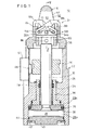
図1において、参照数字10は、本発明の実施の形態に係るクランプ装置を示す。このクランプ装置10は、ワーク12に形成された位置決め用孔部14(図7参照)に挿入されて該ワーク12をクランプする際の位置決めを行う位置決めピン16とワーク12をクランプするクランプアーム18a、18bとを含むワーククランプ部20と、前記位置決めピン16およびクランプアーム18a、18bを略同時に連動させる駆動部(駆動手段)22とを備える。
【0013】
前記駆動部22は、筒状のシリンダチューブ(ボデイ)24と、外周面に環状溝を介してピストンパッキン26が装着され、前記シリンダチューブ24内に形成されたシリンダ室28に沿って変位するピストン30と、一端部が前記ピストン30に係着されたピストンロッド(ロッド部材)32と、前記シリンダチューブ24の膨出部34に保持された筒状の軸受部材36とを有する。なお、前記シリンダチューブ24には、図示しない圧力流体供給源に接続され、ピストン30によって分割された上部側シリンダ室28aおよび下部側シリンダ室28bにそれぞれ圧力流体を供給する複数の流体圧出入ポート(図示せず)が形成されている。
【0014】
前記軸受部材36の内周面には前記ピストンロッド32の外周面に摺接してシール機能を営むロッドパッキン38が装着されている。前記シリンダチューブ24の一端部には、シリンダ室28を閉塞するカバー部材40が止め輪42を介して装着され、前記カバー部材40の外周面には環状溝を介してシリンダ室28を気密に保持するOリング44が装着されている。
【0015】
ピストンロッド32の外周面にはドグ46が固定され、前記ピストン30と一体的に変位するドグ46を検知することにより、ピストン30の位置を検出するセンサ48が配設されている。前記センサ48は、保持部材50を介してシリンダチューブ24に固定されている。
【0016】
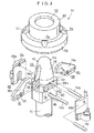
ワーククランプ部20は、図3および図4に示されるように、中央部に円形状の開口部52が形成され、孔部54に挿入される図示しないねじ部材を介してシリンダチューブ24の端部に連結される段付リング体56と、前記円形状の開口部52を介して軸線方向に沿って変位自在に設けられた位置決めピン16とを含む。
【0017】
前記位置決めピン16は、一端部に向かって徐々に縮径するテーパ面58、前記テーパ面58に連続する円周面60および一組のクランプアーム18a、18bが収納される収納用孔部62が設けられたピン部64と、前記ピン部64の下端部に一体的に連結され所定距離離間して相互に対向する一組のブロック体66a、66bとから構成される。前記ブロック体66a、66bには、軸線方向に沿って延在し、後述する一組の軸受部材68a、68bに軸支される固定ピン70が挿通される長孔72と、軸線と略直交する方向に延在し、後述する一組の第1移動ピン74aおよび第2移動ピン74bがそれぞれ係合する係合用孔部76とを有する。
【0018】
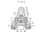
前記段付リング体56には、ワーク12に接触しクランプアーム18a、18bの爪部78との間で該ワーク12をクランプする環状の接触面80が形成され、また、該段付リング体56とシリンダチューブ24との間には、シリンダチューブ24に締結されるボルト82(図5参照)を介して一組の軸受部材68a、68bが介装されている。前記一組の軸受部材68a、68bの上部側には、固定ピン70を軸支する孔部84がそれぞれ形成され、一組のクランプアーム18a、18bは、軸着される前記固定ピン70を回動中心として所定角度回動自在に設けられている。また、前記一組の軸受部材68a、68bには、断面略半長円状に形成され、後述する連結ピン86に係合する溝部88が形成されている。前記溝部88は、連結ピン86に係合することにより、該連結ピン86の抜け止め機能を営むとともに、後述する保持金具90の回り止めの機能を営む。
【0019】
ピストンロッド32の他端部には、連結ピン86を介して保持金具90が連結され、前記保持金具90は軸線方向に沿ってピストンロッド32と一体的に変位するように設けられている。前記保持金具90の略中央部には、固定ピン70によって軸支される一組のクランプアーム作動用の凹部92が形成され、前記凹部92の両側には、それぞれ、右下がりおよび左下がりに所定角度傾斜する一組の係合用長溝94a、94bが形成されている。前記係合用長溝94a、94bには第1移動ピン74aおよび第2移動ピン74bが係合し、前記第1移動ピン74aおよび第2移動ピン74bは、前記係合用長溝94a、94bに沿って転動自在に設けられている。
【0020】
また、前記保持金具90には、段部を介して位置決めピン16のブロック体66a、66bが装着される。この場合、第1移動ピン74aおよび第2移動ピン74bは、ブロック体66a、66bに形成された係合用孔部76、保持金具90に形成された係合用長溝94a、94b、および、クランプアーム18a、18bに形成された長溝96によって支持されるように設けられている。
【0021】
一組のクランプアーム18a、18bは、それぞれ同一形状からなり、ワーク12をクランプする爪部78と、前記爪部78の反対側に設けられ、第1移動ピ74aおよび第2移動ピン74bが係合する長溝96と、固定ピン70が貫通して軸着される孔部98とをそれぞれ有する。
【0022】
なお、前記保持金具90、第1移動ピン74a、第2移動ピン74bおよびブロック体66a、66bは、駆動力伝達手段として機能するものである。
【0023】
本発明の実施の形態に係るクランプ装置10は基本的には以上のように構成されるものであり、次にその動作並びに作用効果について説明する。
【0024】
先ず、図示しない取付手段を介してクランプ装置10をロボットのアーム(図示せず)に取り付けるとともに、図示しないチューブ等の管体の一端部を一組の圧力流体出入ポート(図示せず)にそれぞれ接続し、前記管体の他端部を図示しない圧力流体供給源に接続する。
【0025】
なお、図6Aはアンクランプ状態を、図6Cはクランプ状態をそれぞれ示すものであり、以下、図6Aのアンクランプ状態を初期位置として説明する。
【0026】
この場合、初期位置では、図6Aに示されるように、一組のクランプアーム18a、18bが収納用孔部62内に収納されてピン部64のテーパ面58から外部に突出していない状態にある。また、第1移動ピン74aおよび第2移動ピン74bは、それぞれ、略中央の固定ピン70に近接する係合用長溝94a、94bの上部側に位置しているものとする。
【0027】
また、被固定部材であるワーク12は、図7に示されるように、位置決め用孔部14を有する把手状の係止部材からなり、本実施の形態に係るクランプ装置10を用いて前記ワーク12を平板状のパネル材100の下面に位置決め固定し、図示しない溶接手段を介してパネル材100とワーク12との接合面を溶接するものとする。
【0028】
前記のような準備作業を経た後、図示しないロボットのアームを操作し、ワーク12である係止部材の位置決め用孔部14とクランプ装置10の位置決めピン16とを接近させ、前記位置決め用孔部14と位置決めピン16とが対応する位置に該クランプ装置10を移動させる。
【0029】
このように、ワーク12の位置決め用孔部14と位置決めピン16とが対応する初期位置において、図示しない圧力流体供給源を付勢して一方の圧力流体出入ポートからピストン30の下部側シリンダ室28bに圧力流体(例えば、圧縮空気)を導入する。前記下部側シリンダ室28bに導入された圧力流体の作用下にピストン30が押圧され、該ピストン30がシリンダ室28に沿って上昇する。
【0030】
この場合、連結ピン86を介して連結されたピストンロッド32および保持金具90が前記ピストン30と一体的に上昇し、位置決めピン16のブロック体66a、66bに形成された長孔72に沿って位置決めピン16が所定距離だけ上昇することにより、テーパ面58を介してワーク12の位置決め用孔部14内に位置決めピン16が位置決めされた状態で挿入される。
【0031】
前記連結ピン86を介して連結されたピストンロッド32および保持金具90が前記ピストン30と一体的に上昇することにより、第1移動ピン74aおよび第2移動ピン74bは、所定角度傾斜する係合用長溝94a、94bに沿って下降するとともに、略水平方向に延在する係合用孔部76に沿って変位する。換言すると、前記第1移動ピン74aおよび第2移動ピン74bは、左下がりおよび右下がりに傾斜する係合用長溝94a、94bに沿ってそれぞれ転動しながら下降するとともに、略水平な係合用孔部76に沿って中央部から相互に離間する方向に変位する(図6B参照)。なお、固定ピン70は、軸受部材68a、68bに軸支されているため固定された状態にある。
【0032】
この場合、前記第1移動ピン74aおよび第2移動ピン74bが一組のクランプアーム18a、18bの長溝96に係合することにより、一組のクランプアーム18a、18bは、固定ピン70を回動中心として爪部78が接触面80に対して接近する方向に向かってそれぞれ回動変位する。
【0033】
このように、1つの駆動部22の駆動作用下に、前記位置決めピン16がワーク12の位置決め用孔部14内に挿入されるように上昇すると同時に、前記位置決めピン16に連動してクランプアーム18a、18bが接触面80に向かって接近する方向に回動変位する。
【0034】
なお、前記位置決めピン16が上昇する際の変位量は、ピストン30の変位量よりも小さくなるように設定されている。すなわち、位置決めピン16の変位量は、保持金具90に形成された係合用長溝94a、94bの傾斜角度によって設定され、水平軸に対する傾斜角度が大きくなるのに伴って位置決めピン16の変位量も大きくなる。
【0035】
そして、前記第1移動ピン74aおよび第2移動ピン74bが、図6Cに示されるように、所定角度傾斜する係合用長溝94a、94bの下降した終端に到達し、且つ略水平な係合用孔部76の端部に到達することにより、クランプアーム18a、18bの爪部78と段付リング体56の接触面80との間でワーク12がクランプされる。これによりワーク12は、位置決め用孔部14に挿入された位置決めピン16によって所定の位置に位置決めされた状態でクランプアーム18a、18bを介して固定される(図7参照)。
【0036】
なお、ピストン30の上昇端における停止位置は、ドグ46を介してセンサ48によって検出される。
【0037】
ワーク12がクランプされた状態において、図示しない溶接手段等によって所望の作業が行われた後、図示しない切換弁の切換作用下に上部側シリンダ室28aに圧力流体を供給してピストン30を下降させることにより、位置決めピン16がワーク12の位置決め用孔部14から離間する方向に下降するとともに、前記位置決めピン16に連動してクランプアーム18a、18bが前記とは反対方向に回動変位してクランプ状態が解除される。
【0038】
すなわち、連結ピン86を介して連結されたピストンロッド32および保持金具90が前記ピストン30と一体的に下降することにより、長孔72を介して位置決めピン16が下降し、略同時に第1移動ピン74aおよび第2移動ピン74bは、所定角度傾斜する係合用長溝94a、94bに沿ってそれぞれ転動しながら上昇するとともに、略水平な係合用孔部76に沿って端部から中央部に向かって相互に接近する方向に変位する。従って、位置決め用孔部14から位置決めピン16が離間するように変位すると同時に、一組のクランプアーム18a、18bがワーク12から離間する方向にそれぞれ回動変位し、クランプアーム18a、18bが位置決めピン16に形成された収納用孔部62内に収納されることにより、図6Aに示す初期位置に復帰する。
【0039】
本実施の形態では、1つの駆動部22の駆動作用下に、軸線方向に沿って変位する位置決めピン16と、固定ピン70を回動中心として所定角度回動動作するクランプアーム18a、18bとを略同時に作動させることができる。
【0040】
従って、1つの駆動部22によって位置決めピン16とクランプアーム18a、18bとを連動させることにより、位置決めピン用およびクランプアーム用としてそれぞれ別個の駆動源を必要としないため、装置全体の形状を小型化して製造コストを低減することができる。また、装置全体の重量を軽量化することにより、ロボットのアームに対する負担を軽減し、ロボットのアームの操作性を向上させることができる。
【0041】
また、本実施の形態では、前記位置決めピン16が上昇または下降する際の変位量がピストン30の変位量と異なるように設定されている。すなわち、本実施の形態では、保持金具90に形成された係合用長溝94a、94bの傾斜角度によって位置決めピン16の変位量が設定され、ピストン30の変位量に対して位置決めピン16の変位量が約半分となるように設定されている。このように、ピストン30の変位量に対して位置決めピン16の変位量を小さく設定することにより、パネル材100とワーク12の位置決め用孔部14との離間間隔D(図7参照)が小さい場合であっても好適に使用することが可能となる。
【0042】
さらに、本実施の形態では、駆動源としてシリンダを用いた場合、ピストン30が上死点に到達したときにワーク12をクランプするクランプ状態となるように構成し、ピストン30の受圧面積が最大のとき、すなわち、シリンダの駆動力が最大のときにワーク12をクランプしているため、ワーク12に対するクランプ力を最大限に発揮することができる。
【0043】
なお、本実施の形態では、駆動部22としてシリンダを用いているがこれに限定されるものではなく、図示しない電動アクチュエータ、電動モータ等を用いてもよい。また、本実施の形態では、一組のクランプアーム18a、18bを用いて説明しているがこれに限定されるものではなく、単数あるいは複数のクランプアームを用いることも可能である。
【0044】
【発明の効果】
本発明によれば、以下の効果が得られる。
【0045】
すなわち、単一の駆動手段によって位置決めピンとクランプアームとを略同時に作動させることができる。従って、クランプアームおよび位置決めピンに対応するそれぞれの駆動手段を設ける必要がないため、装置全体の形状を小型化して軽量化を図ることができる。この結果、部品点数を少なくして製造コストを低減することができる。
【図面の簡単な説明】
【図1】本発明の実施の形態に係るクランプ装置の軸線方向に沿った縦断面図である。
【図2】前記クランプ装置を構成するワーククランプ部の斜視図である。
【図3】前記ワーククランプ部の分解斜視図である。
【図4】前記ワーククランプ部の分解斜視図である。
【図5】図1のV−V線に沿った縦断面図である。
【図6】図6A〜図6Cは、それぞれクランプアームの動作を示す動作説明図である。
【図7】ワークがクランプされた状態を示す一部縦断面図である。
【図8】従来技術に係るクランプ装置の縦断面図である。
【符号の説明】
10…クランプ装置 12…ワーク
14…位置決め用孔部 16…位置決めピン
18a、18b…クランプアーム 20…ワーククランプ部
22…駆動部 24…シリンダチューブ
30…ピストン 32…ピストンロッド
56…段付リング体 62…収納用孔部
66a、66b…ブロック体 68a、68b…軸受部材
70…固定ピン 72…長孔
74a、74b…移動ピン 76…係合用孔部
78…爪部 80…接触面
88…溝部 90…保持金具
94a、94b…係合用長溝 96…長溝[0001]
BACKGROUND OF THE INVENTION
The present invention relates to a clamp device capable of clamping a workpiece via a clamp arm that operates under the drive action of a drive unit.
[0002]
[Prior art]
Conventionally, for example, when a component such as an automobile is welded, a clamping device is used to clamp the component (see, for example, JP-A-9-192968).
[0003]
In the clamping device disclosed in Japanese Patent Laid-Open No. 9-192968, as shown in FIG. 8, an outer cylinder 2 having a
[0004]
On the other end side of the outer cylindrical body 2 opposite to the above, by locating the
[0005]
[Problems to be solved by the invention]
However, in the clamping device disclosed in Japanese Patent Laid-Open No. 9-192968 according to the prior art, the locate
[0006]
In addition, when the clamp device is mounted on the robot arm, the entire device becomes large and becomes heavy, which causes a problem that a large load is applied to the robot arm.
[0007]
The present invention has been made in consideration of the above-mentioned problems. Each of the positioning pins and the clamp arm is operated by a single drive unit, and the overall shape of the apparatus is reduced in size and weight to reduce the manufacturing cost. It is an object of the present invention to provide a clamping device that can be reduced.
[0008]
[Means for Solving the Problems]
In order to achieve the above object, the present invention provides a clamp apparatus for clamping a positioned workpiece by a clamp arm by inserting a positioning pin into a positioning hole formed in the workpiece.
Body,
A single drive means for displacing a rod member disposed inside the body along an axial direction of the body;
A clamp arm that rotates a predetermined angle under the displacement action of the rod member;
A positioning pin that is displaced along the axial direction of the body under the displacement action of the rod member;
Driving force transmitting means for operating the clamp arm and the positioning pin substantially simultaneously by transmitting the driving force of the driving means to the clamp arm and the positioning pin, respectively;
Equipped with a,
The driving force transmitting means includes a holding fitting connected to a rod member, an engaging long groove formed in the holding fitting and inclined at a predetermined angle, an engaging hole formed in a positioning pin and extending in a substantially horizontal direction, It includes a long groove formed in the clamp arm and a moving pin that engages with the engaging long groove, the engaging hole, and the long groove, respectively .
[0009]
In this case, before Symbol holding metal fitting may be connected to the rod member by a connecting pin, the connecting pin is provided to engage a groove formed in the bearing member for supporting the clamp arm via a fixing pin Yes. The drive means includes at least a cylinder.
[0010]
According to the present invention, the holding fitting connected to the rod member, the engaging long groove formed in the holding fitting and inclined at a predetermined angle, the engaging hole formed in the positioning pin and extending substantially in the horizontal direction, and the clamp The drive force of a single drive means is supplied to the clamp arm and the positioning pin via the drive force transmission means including a long groove formed in the arm and the engagement long groove, the engagement hole, and a moving pin that respectively engages with the long groove. Is transmitted to. Therefore, the positioning pin is displaced along the axial direction, and the clamp arm is operated almost simultaneously with the positioning pin. As a result, it is not necessary to provide each driving means corresponding to the clamp arm and the positioning pin, so that the overall shape of the apparatus can be reduced in size and weight.
[0011]
DETAILED DESCRIPTION OF THE INVENTION
Preferred embodiments of the clamping device according to the present invention will be described below and described in detail with reference to the accompanying drawings.
[0012]
In FIG. 1,
[0013]
The
[0014]
On the inner peripheral surface of the
[0015]
A
[0016]
As shown in FIGS. 3 and 4, the
[0017]
The positioning
[0018]
The stepped
[0019]
Other end of the
[0020]
Further, the holding
[0021]
The pair of
[0022]
The holding metal fitting 90, the first moving pin 74a, the second moving
[0023]
The
[0024]
First, the clamping
[0025]
6A shows the unclamped state, and FIG. 6C shows the clamped state. Hereinafter, the unclamped state of FIG. 6A will be described as the initial position.
[0026]
In this case, at the initial position, as shown in FIG. 6A, the pair of
[0027]
In addition, as shown in FIG. 7 , the
[0028]
After the preparatory work as described above, a robot arm (not shown) is operated to bring the
[0029]
In this way, at the initial position where the
[0030]
In this case, the
[0031]
When the
[0032]
In this case, when the first moving pin 74a and the second moving
[0033]
In this manner, under the driving action of one driving
[0034]
The displacement amount when the
[0035]
Then, as shown in FIG. 6C, the first moving pin 74a and the second moving
[0036]
The stop position at the rising end of the
[0037]
In a state where the
[0038]
That is, when the
[0039]
In the present embodiment, the
[0040]
Accordingly, by linking the
[0041]
In the present embodiment, the displacement amount when the
[0042]
Further, in the present embodiment, when a cylinder is used as a drive source, the
[0043]
In the present embodiment, a cylinder is used as the
[0044]
【The invention's effect】
According to the present invention, the following effects can be obtained.
[0045]
That is, the positioning pin and the clamp arm can be operated almost simultaneously by a single driving means. Therefore, there is no need to provide each driving means corresponding to the clamp arm and the positioning pin, so that the overall shape of the apparatus can be reduced in size and weight. As a result, the number of parts can be reduced and the manufacturing cost can be reduced.
[Brief description of the drawings]
FIG. 1 is a longitudinal sectional view along an axial direction of a clamp device according to an embodiment of the present invention.
FIG. 2 is a perspective view of a work clamp portion constituting the clamp device.
FIG. 3 is an exploded perspective view of the work clamp portion.
FIG. 4 is an exploded perspective view of the work clamp portion.
5 is a longitudinal sectional view taken along the line VV in FIG. 1. FIG.
6A to 6C are operation explanatory views showing the operation of the clamp arm, respectively.
FIG. 7 is a partial longitudinal sectional view showing a state in which a workpiece is clamped.
FIG. 8 is a longitudinal sectional view of a clamping device according to the prior art.
[Explanation of symbols]
DESCRIPTION OF
Claims (3)
ボデイと、
前記ボデイの内部に配設されたロッド部材を該ボデイの軸線方向に沿って変位させる単一の駆動手段と、
前記ロッド部材の変位作用下に所定角度回動するクランプアームと、
前記ロッド部材の変位作用下にボデイの軸線方向に沿って変位する位置決めピンと、
前記駆動手段の駆動力をクランプアームおよび位置決めピンにそれぞれ伝達することにより、前記クランプアームおよび位置決めピンをそれぞれ略同時に作動させる駆動力伝達手段と、
を備え、
前記駆動力伝達手段は、ロッド部材に連結された保持金具と、前記保持金具に形成され所定角度傾斜する係合用長溝と、位置決めピンに形成され略水平方向に延在する係合用孔部と、クランプアームに形成された長溝と、前記係合用長溝、係合用孔部および長溝にそれぞれ係合する移動ピンとを含むことを特徴とするクランプ装置。In a clamping device for clamping a positioned workpiece by a clamp arm by inserting a positioning pin into a positioning hole formed in the workpiece,
Body,
A single drive means for displacing a rod member disposed inside the body along an axial direction of the body;
A clamp arm that rotates a predetermined angle under the displacement of the rod member;
A positioning pin that is displaced along the axial direction of the body under the displacement action of the rod member;
Driving force transmitting means for operating the clamp arm and the positioning pin substantially simultaneously by transmitting the driving force of the driving means to the clamp arm and the positioning pin, respectively;
Equipped with a,
The driving force transmitting means includes a holding fitting connected to a rod member, an engaging long groove formed in the holding fitting and inclined at a predetermined angle, an engaging hole formed in a positioning pin and extending in a substantially horizontal direction, A clamp device comprising: a long groove formed in a clamp arm; and a moving pin that engages with the engaging long groove, the engaging hole, and the long groove, respectively .
前記保持金具は、連結ピンによってロッド部材と連結され、前記連結ピンは、固定ピンを介してクランプアームを軸支する軸受部材に形成された溝部に係合するように設けられることを特徴とするクランプ装置。The apparatus of claim 1 .
The holding metal fitting is connected to a rod member by a connection pin, and the connection pin is provided to engage with a groove formed in a bearing member that pivotally supports a clamp arm via a fixing pin. Clamping device.
前記駆動手段は、少なくともシリンダを含むことを特徴とするクランプ装置。The apparatus of claim 1.
The clamping device according to claim 1, wherein the driving means includes at least a cylinder.
Priority Applications (8)
| Application Number | Priority Date | Filing Date | Title |
|---|---|---|---|
| JP14401999A JP3634190B2 (en) | 1999-05-24 | 1999-05-24 | Clamping device |
| TW089109316A TW505553B (en) | 1999-05-24 | 2000-05-16 | Clamp apparatus |
| DE60001597T DE60001597T2 (en) | 1999-05-24 | 2000-05-17 | jig |
| EP00110497A EP1055474B1 (en) | 1999-05-24 | 2000-05-17 | Clamp apparatus |
| ES00110497T ES2192502T3 (en) | 1999-05-24 | 2000-05-17 | CLAMPING APPARATUS |
| KR10-2000-0026612A KR100367285B1 (en) | 1999-05-24 | 2000-05-18 | Clamp Apparatus |
| US09/575,795 US6364300B1 (en) | 1999-05-24 | 2000-05-22 | Clamp apparatus |
| CNB001089668A CN1197686C (en) | 1999-05-24 | 2000-05-24 | Clamp device |
Applications Claiming Priority (1)
| Application Number | Priority Date | Filing Date | Title |
|---|---|---|---|
| JP14401999A JP3634190B2 (en) | 1999-05-24 | 1999-05-24 | Clamping device |
Publications (2)
| Publication Number | Publication Date |
|---|---|
| JP2000326167A JP2000326167A (en) | 2000-11-28 |
| JP3634190B2 true JP3634190B2 (en) | 2005-03-30 |
Family
ID=15352444
Family Applications (1)
| Application Number | Title | Priority Date | Filing Date |
|---|---|---|---|
| JP14401999A Expired - Fee Related JP3634190B2 (en) | 1999-05-24 | 1999-05-24 | Clamping device |
Country Status (8)
| Country | Link |
|---|---|
| US (1) | US6364300B1 (en) |
| EP (1) | EP1055474B1 (en) |
| JP (1) | JP3634190B2 (en) |
| KR (1) | KR100367285B1 (en) |
| CN (1) | CN1197686C (en) |
| DE (1) | DE60001597T2 (en) |
| ES (1) | ES2192502T3 (en) |
| TW (1) | TW505553B (en) |
Families Citing this family (97)
| Publication number | Priority date | Publication date | Assignee | Title |
|---|---|---|---|---|
| FR2795013B1 (en) * | 1999-06-18 | 2001-08-31 | Michel Beffrieu | CENTERING AND TIGHTENING TOOL |
| MXPA01012811A (en) | 2001-01-18 | 2002-11-04 | Progressive Tool & Ind Co | Clamping locator. |
| US6698736B2 (en) | 2001-01-18 | 2004-03-02 | Progressive Tool & Industries Co. | Clamping locator |
| DE20105449U1 (en) * | 2001-03-28 | 2001-08-09 | Festo Ag & Co | Fluid operated gripper |
| FR2832341B1 (en) * | 2001-11-16 | 2004-03-19 | Fiam | PILOT CENTERING AND TIGHTENING TOOL |
| FR2837118B1 (en) * | 2002-03-18 | 2004-08-06 | Bema Ingenierie | CLAMPING HEAD COMPRISING A CENTERING DRIVER WITH RETRACTABLE CLAMPS |
| US6827345B2 (en) * | 2003-02-20 | 2004-12-07 | The Boeing Company | Wedge-lock fastener and associated installation and assembly methods |
| JP4613476B2 (en) * | 2003-04-03 | 2011-01-19 | 日産自動車株式会社 | Clamp jig |
| JP3941059B2 (en) * | 2003-07-01 | 2007-07-04 | Smc株式会社 | Locate clamp device |
| ITMI20031454A1 (en) * | 2003-07-16 | 2005-01-17 | Univer Spa | COMPACT BINDING DEVICE FOR WORK PIECES |
| US20050035516A1 (en) * | 2003-08-14 | 2005-02-17 | Sawdon Edwin G. | Sealed pin locator clamp |
| US6902159B2 (en) * | 2003-08-21 | 2005-06-07 | Btm Corporation | Sealed pin locating and clamping apparatus |
| US7815176B2 (en) | 2003-09-11 | 2010-10-19 | Phd, Inc. | Lock mechanism for pin clamp assembly |
| JP2007512142A (en) * | 2003-11-24 | 2007-05-17 | ミサティ ソシエダード リミターダ | Clamp for automated welding equipment |
| US7182326B2 (en) * | 2004-04-02 | 2007-02-27 | Phd, Inc. | Pin clamp |
| US7516948B2 (en) * | 2004-04-02 | 2009-04-14 | Phd, Inc. | Pin clamp accessories |
| JP4062315B2 (en) * | 2004-04-12 | 2008-03-19 | 日産自動車株式会社 | Positioning clamp device and its spatter intrusion prevention method |
| JP4534640B2 (en) * | 2004-07-16 | 2010-09-01 | 日産自動車株式会社 | Work positioning method using locate device |
| ITMI20041584A1 (en) * | 2004-08-02 | 2004-11-02 | Univer Spa | SYSTEM FOR THE DETECTION OF OPERATING POSITIONS FOR A RETAINING DEVICE FOR WORKPIECES |
| US7311301B2 (en) * | 2004-08-03 | 2007-12-25 | Delaware Capital Formation, Inc. | Hook pin unit having weld slag protection |
| US7029000B2 (en) * | 2004-09-07 | 2006-04-18 | Btm Corporation | Sealed locking pin locator clamp |
| ATE405378T1 (en) * | 2004-10-09 | 2008-09-15 | Staudinger Forschungs Und Entw | TENSIONING DEVICE |
| US7448607B2 (en) * | 2004-12-15 | 2008-11-11 | Phd, Inc. | Pin clamp assembly |
| US7669840B2 (en) * | 2005-01-25 | 2010-03-02 | Delaware Capital Formation, Inc. | Hook clamp unit |
| ITMI20050436A1 (en) * | 2005-03-17 | 2006-09-18 | Univer Spa | LOCKING AND CENTERING DEVICE FOR PIECES TO BE WORKED WITH A HOOK-LOCKING ORGAN |
| KR100692749B1 (en) | 2005-08-02 | 2007-03-09 | 현대자동차주식회사 | jig for positioning shock absorber housing panel |
| US7686286B2 (en) * | 2005-08-26 | 2010-03-30 | Delaware Capital Formation, Inc. | Variable thickness pin clamp |
| US20070267795A1 (en) * | 2006-02-06 | 2007-11-22 | Parag Patwardhan | Pin clamp transfer assembly and method of transferring a workpiece |
| KR100644912B1 (en) | 2006-02-23 | 2006-11-13 | 한국에스엠씨공압(주) | Clamp assembly |
| JP2008229777A (en) * | 2007-03-20 | 2008-10-02 | Koganei Corp | Positioning clamping device |
| WO2008157698A2 (en) | 2007-06-19 | 2008-12-24 | Phd, Inc. | Pin clamp assembly |
| JP2009107076A (en) * | 2007-10-31 | 2009-05-21 | Smc Corp | Clamp device |
| JP5418997B2 (en) * | 2008-01-22 | 2014-02-19 | Smc株式会社 | Clamping device |
| US8376336B2 (en) * | 2008-06-18 | 2013-02-19 | Phd, Inc. | Strip off pin clamp |
| CN101733658B (en) * | 2009-12-08 | 2014-10-22 | 杨小龙 | Multi-station processing pincer-like fixture |
| CN102091961B (en) * | 2009-12-14 | 2012-05-02 | 哈尔滨汽轮机厂有限责任公司 | Wheel disc locking and positioning pin for turbine |
| JP2011235412A (en) * | 2010-05-12 | 2011-11-24 | Honda Motor Co Ltd | Clamping device |
| US8459626B2 (en) * | 2010-05-28 | 2013-06-11 | Btm Corporation | Pin clamp |
| CN102248418B (en) * | 2011-06-23 | 2012-12-05 | 张家港玉成精机有限公司 | Automatic positioning wrench work clamp |
| US20130255058A1 (en) * | 2012-03-28 | 2013-10-03 | Soucy International Inc. | Attachment System and Method of Using the Same |
| CN102649237B (en) * | 2012-05-28 | 2015-02-04 | 长城汽车股份有限公司 | Steering knuckle center hole and brake caliper mounting hole processing clamp |
| US9248515B2 (en) * | 2013-03-18 | 2016-02-02 | Factory Automation Technology Co., Ltd. | Wheel rim processing machine |
| CN103521977B (en) * | 2013-09-30 | 2015-06-10 | 北京汽车股份有限公司 | Simple hook pin |
| CN104625992B (en) * | 2013-11-06 | 2017-12-05 | 富泰华工业(深圳)有限公司 | Positioner |
| US9144889B2 (en) * | 2014-03-03 | 2015-09-29 | Praxis Industries, Llc | Clamping assembly |
| CN103801884A (en) * | 2014-03-04 | 2014-05-21 | 安徽江淮汽车股份有限公司 | Clamping positioning tool and welding equipment |
| CN104646894B (en) * | 2014-06-10 | 2016-06-29 | 上海汇众汽车制造有限公司 | The interlocking gear of multipoint positioning and compression |
| CN104162796A (en) * | 2014-08-20 | 2014-11-26 | 无锡众望四维科技有限公司 | Clamping device used for dead bolt |
| CZ307625B6 (en) * | 2014-09-09 | 2019-01-23 | Ĺ KODA AUTO a.s. | Device to transport car body on production line |
| US9770810B2 (en) * | 2014-11-12 | 2017-09-26 | De-Sta-Co Europe Gmbh | Pin clamp |
| CN104552077A (en) * | 2015-02-03 | 2015-04-29 | 安徽机电职业技术学院 | Testing and fixing clamp for automobile structural sheet metal parts |
| CN105983929B (en) * | 2015-03-04 | 2018-05-15 | 富鼎电子科技(嘉善)有限公司 | Positioner |
| CN104772723A (en) * | 2015-03-26 | 2015-07-15 | 胡莉莉 | Multifunctional fixed seat |
| CN104786170A (en) * | 2015-04-21 | 2015-07-22 | 苏州铭德铝业有限公司 | Clamping assembly |
| JP6355054B2 (en) * | 2015-04-24 | 2018-07-11 | Smc株式会社 | Clamping device |
| CN105252453A (en) * | 2015-09-17 | 2016-01-20 | 苏州新协力特种工业模板有限公司 | Clamping device for artificial board test |
| CN105108682A (en) * | 2015-09-21 | 2015-12-02 | 江苏扬碟钻石工具有限公司 | End face positioning block |
| CN105172326A (en) * | 2015-09-30 | 2015-12-23 | 苏州恩欧西精密机械制造有限公司 | Hanging plate clamping device |
| CN105082020A (en) * | 2015-09-30 | 2015-11-25 | 苏州恩欧西精密机械制造有限公司 | Hanging plate clamping device provided with pressing boards with through holes |
| CN105269485B (en) * | 2015-10-22 | 2017-08-11 | 芜湖豫新世通汽车空调有限公司 | Rotatable friction detection and localization instrument |
| CN105437106A (en) * | 2015-12-09 | 2016-03-30 | 无锡西源电力装备厂 | Pipe machining and fixing clamp |
| CN105437107B (en) * | 2015-12-09 | 2017-08-11 | 广东长盈精密技术有限公司 | Tear pressurize fixture device open |
| CN105437117B (en) * | 2015-12-16 | 2018-06-19 | 嵊州市银海机械有限公司 | A kind of clamping device applied to mechanical fitting production |
| CN105437118B (en) * | 2015-12-23 | 2017-09-12 | 沈阳中辰钢结构工程有限公司 | A kind of square tube concrete column shop assembled mold |
| CN105458974B (en) * | 2015-12-28 | 2017-07-04 | 苏州赛腾精密电子股份有限公司 | A kind of unidirectional drive clamping and pressing device |
| CN105437113A (en) * | 2015-12-29 | 2016-03-30 | 常熟市徐润机电有限公司 | Gauge clamp |
| CN105619287B (en) * | 2016-02-29 | 2017-09-01 | 迈特通信设备(苏州)有限公司 | A kind of fast pneumatic frock clamp |
| CN105856097B (en) * | 2016-03-22 | 2017-10-10 | 苏州伽蓝致远电子科技股份有限公司 | Dispensing frock is bonded between a kind of fiber optic connector ferrule and briquetting |
| CN105619288B (en) * | 2016-03-28 | 2017-10-03 | 义乌市光贵服装商行 | It is a kind of to be used for sheet-like workpiece and clamp assemblies and its application method with LED light |
| CN105856100A (en) * | 2016-05-26 | 2016-08-17 | 苏州万盛塑胶科技股份有限公司 | Workpiece clamping mechanism |
| CN105856104A (en) * | 2016-06-02 | 2016-08-17 | 常州市金海珑机械制造有限公司 | Hardware processing and clamping device |
| CN105881409A (en) * | 2016-06-16 | 2016-08-24 | 常州欣博特减速机有限公司 | Hardware part fixing device with good fixing effect |
| CN107553361A (en) * | 2016-06-30 | 2018-01-09 | 天津市汇点机电设备开发有限公司 | A kind of angle localization method of gear and sprocket wheel |
| CN105881412B (en) * | 2016-06-30 | 2018-04-06 | 中石化石油工程技术服务有限公司 | Tension test cable cleat |
| CN106141954B (en) * | 2016-07-26 | 2017-11-24 | 北京工业大学 | A kind of fixture of the energy acquisition opposite side freely supported structure TRT based on vibration |
| CN106272153B (en) * | 2016-08-24 | 2018-01-12 | 天津宝骏科技股份有限公司 | Steel plate class workpiece fixation device |
| CN106272166B (en) * | 2016-09-26 | 2018-05-29 | 南昌航空大学 | A kind of long beam multistation automatic fixture of aircraft |
| EP3299124B1 (en) | 2016-09-27 | 2019-07-24 | UNIVER S.p.A. | Device for positioning and clamping of workpieces |
| JP6716081B2 (en) * | 2016-10-28 | 2020-07-01 | 株式会社コスメック | Link type clamp device |
| CN106514511B (en) * | 2016-11-29 | 2018-03-27 | 延锋伟世通电子科技(南京)有限公司 | A kind of auto navigation screen module positioning fixture for assembling |
| CN106493659B (en) * | 2016-12-06 | 2018-09-21 | 博众精工科技股份有限公司 | A kind of Carrier mechanism |
| CN106737297B (en) * | 2017-01-03 | 2018-09-04 | 京东方科技集团股份有限公司 | A kind of curved surface assembling equipment |
| CN106625353B (en) * | 2017-02-16 | 2019-01-22 | 郑州新交通汽车板簧有限公司 | Dedicated leaf spring general assembly frame |
| CN106826624B (en) | 2017-02-28 | 2018-10-12 | 京东方科技集团股份有限公司 | Vacuum suction unit and vacuum suction microscope carrier |
| IT201700023373A1 (en) * | 2017-03-02 | 2018-09-02 | O M G S R L | DEVICE FOR CONNECTING A TOOL ON A MACHINE |
| CN107234559B (en) * | 2017-05-09 | 2018-11-27 | 浙江零跑科技有限公司 | A kind of bushing test fixture |
| CN107225527A (en) * | 2017-06-15 | 2017-10-03 | 芜湖宏景电子股份有限公司 | Auto navigation screen assembly fixture |
| CN107309824A (en) * | 2017-07-07 | 2017-11-03 | 何联菲 | A kind of hardware fixture |
| CN107971943B (en) * | 2017-11-23 | 2020-02-11 | 中国航发沈阳黎明航空发动机有限责任公司 | Measuring tool for limiting measurement and using method thereof |
| KR20190107848A (en) * | 2018-03-13 | 2019-09-23 | 삼성전자주식회사 | Fixing device and machining apparatus including the same |
| CN108792491A (en) * | 2018-08-31 | 2018-11-13 | 烟台宇信科技有限公司 | A kind of variable flexible compression supporting and positioning device of diameter |
| CN108869499B (en) * | 2018-09-03 | 2024-04-02 | 菲斯达精密工业部件(苏州)有限公司 | Hydraulic locating pin |
| DE102020003577B3 (en) * | 2020-06-16 | 2021-06-10 | Olaf und André Tünkers GbR (vertretungsberechtigter Gesellschafter: Dipl.-Ing. Olaf Tünkers, 40883 Ratingen) | Underbody tensioner with toggle joint and link guide, for use in body construction in the automotive industry |
| CN111747163B (en) * | 2020-07-15 | 2022-04-15 | 苏州润弘安创自动化科技有限公司 | Positioning and clamping device and feeding system |
| ES2913373B2 (en) * | 2020-12-01 | 2022-10-03 | Seat Sa | DEVICE FOR HOLDING AND CENTERING PARTS IN PRODUCTION SYSTEMS, PRODUCTION SYSTEM THAT CONTAINS IT AND OPERATING METHOD OF SAID DEVICE |
| CN113524077B (en) * | 2021-07-30 | 2022-12-20 | 深圳市振海机电设备有限公司 | Center positioning fixture device |
| CN114367846A (en) * | 2022-02-23 | 2022-04-19 | 重庆渝江压铸有限公司 | Pressing mechanism |
Family Cites Families (8)
| Publication number | Priority date | Publication date | Assignee | Title |
|---|---|---|---|---|
| US4294444A (en) * | 1980-04-29 | 1981-10-13 | World Wide Oil Tools, Inc. | Pipe gripping vise |
| JPH06170604A (en) * | 1992-12-09 | 1994-06-21 | Murata Mach Ltd | Spindle construction for lathe |
| FR2733930B1 (en) * | 1995-05-12 | 1997-06-06 | Preciflex Syst | DEVICE FOR INDEXING A PART THROUGH A HOLE OF THIS PART |
| JP3462330B2 (en) | 1996-01-19 | 2003-11-05 | 株式会社コガネイ | Positioning clamp device |
| DE19616441C1 (en) * | 1996-04-25 | 1997-06-26 | Tuenkers Maschinenbau Gmbh | Toggle joint clamping device for vehicle bodywork, with grip head |
| FR2755049A1 (en) * | 1996-10-25 | 1998-04-30 | Ragonot | Compact gripping head for handling metal sheet |
| FR2757437B1 (en) * | 1996-12-24 | 1999-02-26 | Bruyn Gerard De | PILOT CENTERING AND TIGHTENING TOOL |
| FR2766750B1 (en) * | 1997-07-31 | 1999-09-17 | Grp D Etudes Carrosseries Et O | PILOT CLAMPING DEVICE |
-
1999
- 1999-05-24 JP JP14401999A patent/JP3634190B2/en not_active Expired - Fee Related
-
2000
- 2000-05-16 TW TW089109316A patent/TW505553B/en not_active IP Right Cessation
- 2000-05-17 EP EP00110497A patent/EP1055474B1/en not_active Expired - Lifetime
- 2000-05-17 ES ES00110497T patent/ES2192502T3/en not_active Expired - Lifetime
- 2000-05-17 DE DE60001597T patent/DE60001597T2/en not_active Expired - Lifetime
- 2000-05-18 KR KR10-2000-0026612A patent/KR100367285B1/en active IP Right Grant
- 2000-05-22 US US09/575,795 patent/US6364300B1/en not_active Expired - Lifetime
- 2000-05-24 CN CNB001089668A patent/CN1197686C/en not_active Expired - Lifetime
Also Published As
| Publication number | Publication date |
|---|---|
| CN1197686C (en) | 2005-04-20 |
| JP2000326167A (en) | 2000-11-28 |
| US6364300B1 (en) | 2002-04-02 |
| DE60001597T2 (en) | 2004-01-08 |
| TW505553B (en) | 2002-10-11 |
| EP1055474B1 (en) | 2003-03-12 |
| ES2192502T3 (en) | 2003-10-16 |
| CN1274657A (en) | 2000-11-29 |
| KR100367285B1 (en) | 2003-01-09 |
| EP1055474A1 (en) | 2000-11-29 |
| KR20010049362A (en) | 2001-06-15 |
| DE60001597D1 (en) | 2003-04-17 |
Similar Documents
| Publication | Publication Date | Title |
|---|---|---|
| JP3634190B2 (en) | Clamping device | |
| JP4789006B2 (en) | Clamping device | |
| KR101056636B1 (en) | Clamp device | |
| US9409282B2 (en) | Clamp apparatus | |
| JP4892668B2 (en) | Clamping device | |
| US6902159B2 (en) | Sealed pin locating and clamping apparatus | |
| JP5418997B2 (en) | Clamping device | |
| US6641123B2 (en) | Clamp apparatus | |
| US5280892A (en) | Positioning fixture for welding operations | |
| JP5212830B2 (en) | Clamping device | |
| CN105437252A (en) | Gripper | |
| JP2009214204A (en) | Robot hand | |
| JP6240981B2 (en) | Welding gun | |
| JP3462330B2 (en) | Positioning clamp device | |
| JP2002263975A (en) | Clamping device | |
| KR102374473B1 (en) | clamping device | |
| TWI655992B (en) | Fixture device | |
| JP2012020355A (en) | Tilt table device | |
| JP4161838B2 (en) | Component assembling apparatus and method of manufacturing rotating electric machine |
Legal Events
| Date | Code | Title | Description |
|---|---|---|---|
| A977 | Report on retrieval |
Free format text: JAPANESE INTERMEDIATE CODE: A971007 Effective date: 20040126 |
|
| A131 | Notification of reasons for refusal |
Free format text: JAPANESE INTERMEDIATE CODE: A131 Effective date: 20040217 |
|
| A521 | Request for written amendment filed |
Free format text: JAPANESE INTERMEDIATE CODE: A523 Effective date: 20040415 |
|
| TRDD | Decision of grant or rejection written | ||
| A01 | Written decision to grant a patent or to grant a registration (utility model) |
Free format text: JAPANESE INTERMEDIATE CODE: A01 Effective date: 20041124 |
|
| A61 | First payment of annual fees (during grant procedure) |
Free format text: JAPANESE INTERMEDIATE CODE: A61 Effective date: 20041222 |
|
| R150 | Certificate of patent or registration of utility model |
Ref document number: 3634190 Country of ref document: JP Free format text: JAPANESE INTERMEDIATE CODE: R150 Free format text: JAPANESE INTERMEDIATE CODE: R150 |
|
| FPAY | Renewal fee payment (event date is renewal date of database) |
Free format text: PAYMENT UNTIL: 20090107 Year of fee payment: 4 |
|
| R250 | Receipt of annual fees |
Free format text: JAPANESE INTERMEDIATE CODE: R250 |
|
| FPAY | Renewal fee payment (event date is renewal date of database) |
Free format text: PAYMENT UNTIL: 20100107 Year of fee payment: 5 |
|
| R250 | Receipt of annual fees |
Free format text: JAPANESE INTERMEDIATE CODE: R250 |
|
| FPAY | Renewal fee payment (event date is renewal date of database) |
Free format text: PAYMENT UNTIL: 20110107 Year of fee payment: 6 |
|
| R250 | Receipt of annual fees |
Free format text: JAPANESE INTERMEDIATE CODE: R250 |
|
| FPAY | Renewal fee payment (event date is renewal date of database) |
Free format text: PAYMENT UNTIL: 20120107 Year of fee payment: 7 |
|
| R250 | Receipt of annual fees |
Free format text: JAPANESE INTERMEDIATE CODE: R250 |
|
| FPAY | Renewal fee payment (event date is renewal date of database) |
Free format text: PAYMENT UNTIL: 20130107 Year of fee payment: 8 |
|
| R250 | Receipt of annual fees |
Free format text: JAPANESE INTERMEDIATE CODE: R250 |
|
| FPAY | Renewal fee payment (event date is renewal date of database) |
Free format text: PAYMENT UNTIL: 20140107 Year of fee payment: 9 |
|
| R250 | Receipt of annual fees |
Free format text: JAPANESE INTERMEDIATE CODE: R250 |
|
| R250 | Receipt of annual fees |
Free format text: JAPANESE INTERMEDIATE CODE: R250 |
|
| R250 | Receipt of annual fees |
Free format text: JAPANESE INTERMEDIATE CODE: R250 |
|
| R250 | Receipt of annual fees |
Free format text: JAPANESE INTERMEDIATE CODE: R250 |
|
| R250 | Receipt of annual fees |
Free format text: JAPANESE INTERMEDIATE CODE: R250 |
|
| R250 | Receipt of annual fees |
Free format text: JAPANESE INTERMEDIATE CODE: R250 |
|
| LAPS | Cancellation because of no payment of annual fees |