EP0803217A2 - Dispositif de suspension amovible et de manipulation d'un rideau ou store - Google Patents
Dispositif de suspension amovible et de manipulation d'un rideau ou store Download PDFInfo
- Publication number
- EP0803217A2 EP0803217A2 EP97106523A EP97106523A EP0803217A2 EP 0803217 A2 EP0803217 A2 EP 0803217A2 EP 97106523 A EP97106523 A EP 97106523A EP 97106523 A EP97106523 A EP 97106523A EP 0803217 A2 EP0803217 A2 EP 0803217A2
- Authority
- EP
- European Patent Office
- Prior art keywords
- curtain
- curtain rail
- head part
- guide slot
- rail
- Prior art date
- Legal status (The legal status is an assumption and is not a legal conclusion. Google has not performed a legal analysis and makes no representation as to the accuracy of the status listed.)
- Withdrawn
Links
Images
Classifications
-
- A—HUMAN NECESSITIES
- A47—FURNITURE; DOMESTIC ARTICLES OR APPLIANCES; COFFEE MILLS; SPICE MILLS; SUCTION CLEANERS IN GENERAL
- A47H—FURNISHINGS FOR WINDOWS OR DOORS
- A47H15/00—Runners or gliders for supporting curtains on rails or rods
- A47H15/04—Gliders
Definitions
- the invention relates to a device for releasable attachment, for moving and removing a curtain or a blind in a curtain track.
- the insertion opening in the curtain track is usually covered with a cap after all sliders have been inserted, or the entire track is initially provided with a stop element so that when the sliders move in the tread, they do not accidentally come out of the opening or over the rail edge fall down.
- DE 41 17 863 describes a device for releasable fastening and for moving a curtain door, which describes a flexible elastic glider in the form of an arrow or in the shape of a cone.
- the tip of this slider is elastically deformable, in particular compressible, so that this slider can be inserted into the slot of the curtain rail with slight pressure without a special insertion opening having to be provided for this.
- these elastic, flexible sliders can be arranged on a transport or preassembly rail and can be pressed into the slot of the curtain rail by means of this transport rail. This has the advantage that, for example, an entire store can be placed on this transport rail and then pressed into the curtain rail on the ceiling.
- this fastening device After reaching through the elastic arrow-shaped or conical outer walls of the glider, they spread back into their original shape and thus prevent them from slipping back out of the slot in the curtain rail.
- this fastening device has a shoulder-like thickening, which forms a kind of abutment when inserted into the curtain slot.
- This device is quite suitable for introducing a curtain relatively easily into a curtain rail.
- removing the curtain or store is difficult or very complex, because this can only be done in a known manner only by gradually removing the slider from the rail at the end of the rail or at a separately provided opening in the slot Need to become.
- the object of the present invention to develop a device for releasably attaching, moving and removing a curtain or blind, which is equally quickly and easily inserted into the slot of the curtain rail and simple and quick, with a few simple steps from this curtain rail can be removed. Furthermore, the invention is the Object of the task to design this device so that it can be ordered quickly, easily and inexpensively.
- this object is achieved by a device according to the characterizing part of claim 1. Developments of this device are the subject of the dependent claims.
- the device according to the invention for releasably attaching, moving and removing a curtain or a store in a curtain rail has sliders, each of which has a head part that can be guided on a track of the curtain rail and has a lower receiving part that can be connected to the curtain or store is.
- the head part and the receiving part for the curtain are connected to one another via a connecting element.
- the head part consists of a sliding area which guides the slider on the track of the curtain rail and a fixing area which guides the slider in the guide slot of the curtain rail.
- a connecting element for connecting these device elements to one another is arranged laterally on the fixing region between the head part and the receiving part.
- the head part and connecting element are designed in the manner of a profile angle, the part of the profile angle which forms the head part of the device projecting beyond the leg connected to it.
- the fixing element is designed in the manner of a support which does not completely cover the head part within the profile angle and projects upwards from it in the direction of the connecting element.
- the sliding area of the head part of the slider is rectangular, in particular designed like a hammer head.
- the fixing area is arranged below the sliding area, the fixing area being dimensioned such that it almost completely closes the width of the guide slot of the curtain rail.
- the sliding area of the head part of the glider is guided on the track of the curtain track. In terms of its width, this sliding area is wider than that Slit of the curtain rail, so that the elements of the sliding area overlapping the slit virtually form the force-absorbing elements and carry the entire curtain or store.
- These sliding areas of the head part must be designed to be correspondingly stable.
- a fixing area is connected to these sliding areas.
- the dimension of the fixing area corresponds approximately to the width of the guide slot of the curtain rail.
- This fixing area extends below the sliding area up to the connecting element.
- the connecting element and the fixing area close the guide slot of the curtain rail almost completely to the extent that a slight sliding movement of the device in the guide slot is possible.
- the fixing area is designed in its horizontal extent so that it essentially corresponds to the thickness of the track of the curtain track.
- the thus designed head part of the device for releasably fastening and for moving a curtain or a blind has the decisive advantage that it can be easily and quickly inserted into the guide slot at any point on the curtain rail. All that is necessary is that the device itself does not have to be guided vertically but at an angle ⁇ 90 ° to the guide slot, the connecting element between the head part and the receiving element having to be arranged on the side facing away from the curtain rail. In this slightly angled position, the head part can be inserted into the slot in the guide rail. If the head part is completely inserted into the rail, it engages with the longer leg of the head part on a track of the guide slot, so that the complete head part can be inserted into the slot.
- the fixing area fixes the device during the sliding movement within the rail in such a way that it is not inadvertently brought into an angled position by itself from the vertical can be and thus can come loose from the guide slot. In this way, a curtain can be quickly and easily fixed at various locations on the rail without the individual sliders having to be arranged in a specific order.
- Another great advantage is the easy and quick removal of curtains and blinds by simply pulling them from the vertical to an angle of ⁇ 90 °, whereby the sliders automatically release themselves from the guide rail when this angled position is reached. In this way it is quick and easy to remove the entire curtain from the curtain rail with a slight swing.
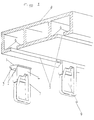
- curtain rails can now be formed without additional insertion openings for holding devices.
- the curtain rail 8 shown in FIG. 1 has two guide slots 5, each of which has two running surfaces 6 for sliders introduced into these guide slots 5. These guide slots 5 have no additional receiving openings.
- One of the two sliders 9 arranged below the curtain rail has already been introduced into the guide slot 5 of the curtain rail.
- the glider 9 is inserted into the guide slot 5 of the curtain rail 8, as can be seen in FIG. 2, by bending it slightly from the vertical. Once the receiving part for the curtain 7 of the glider again shows in the vertical, that is, as soon as an approximately right angle is reached between the receiving part and the curtain rail, the fixing area 3 slides into the guide slot 5.
- the sliding areas of the slider cover the running surfaces 6 of the curtain rail.
- the fixing area of the slider extends within the guide slot 5 to the connecting element 4, so that when the slider is fixed in the guide rail, the fixing element 3 on the one hand and the connecting element 4 on the other hand almost abuts the inner surface of the guide slot, so that the slider within the guide slot 5 can be moved on the track without the sliding areas 2 can detach from the track 6 of the guide rail 8 and can slide into the guide slot.
- the fixing area 3 and the connecting element are designed such that they cover almost the entire width of the guide slot, so that only a small difference in width occurs, which enables easy slidability within the guide slot.
- the head part of the slider 1 is designed like a hammer head.
- the tapering area of the hammer-head-like head part 1 tilts in the direction of the connecting element 4.
- This tapering shape in the direction of the connecting element enables simple and easy insertion of the head part into the guide slot 5 from the vertical angled form, the slider with respect to the curtain rail 8 is angled so that the angle between connecting element 4 and curtain rail 8 is> 90 ° and the angle between fixing area 3 and curtain rail 8 is ⁇ 90 °.
- These hammer head-like head parts 1 have the great advantage that they do not require any receiving opening in the guide slot 5 and can be introduced into the guide slot at any point.
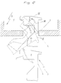
- Fig. 2 shows a schematic representation of the angular positions of the head part or the entire device for fastening for inserting and fixing the device within the guide slot.
- Fig. 2 shows a schematic representation of the introduction of a fastening device or a slider 9 in the guide slot 5 of a curtain rail 8 and the relative positions and movements of the slider to the curtain rail 8 and its tread 6.
- the slider is in position I vertically below of the guide slot 5.
- the curtain rail 8, more precisely the underside of the curtain rail 8, and the fixing area 3 and the connecting element 4 form a right angle. From this right-angled position, the device is angled in position II in the direction of the fixing element, the angle between the curtain rail 8 and fixing element being reduced when the head part is inserted into the guide slot, whereas the angle between the curtain rail 8 and connecting element 4 is reduced when the slide is inserted into the guide slot enlarged.
- the slider After penetrating the guide slot 5, the slider is again moved to the vertical, the sliding areas being arranged above the running surface 6 of the curtain rail. As soon as the slider is again in the vertical direction, it slides downward, the sliding areas 2 coming to rest on the running surfaces and the fixing area 3 being arranged within the guide slot 5.
- the slider is movably fixed within the guide slot of the curtain rail after insertion into the guide slot 5.
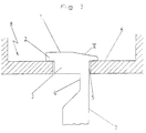
- the slider is introduced into the guide slot 5 of the curtain rail 8.
- the sliding surfaces 2 rest on the running surfaces 6 within the curtain rail.
- the head part 1 which is designed like a hammer head, projects into the interior of the curtain rail.
- the tapering part of the hammer head inclines in the direction of the connecting element which is arranged on the side of the head part.
- the fixing element 3 and the connecting element 4 cover almost the entire width of the guide slot 5 and protrude within the slot towards the floor, the fixing element being flush with the lower edge of the curtain rail.
- the connecting element 4 protrudes from the guide slot and merges into a receiving element 7 for the curtain or store.
Landscapes
- Curtains And Furnishings For Windows Or Doors (AREA)
Applications Claiming Priority (2)
| Application Number | Priority Date | Filing Date | Title |
|---|---|---|---|
| DE19616541 | 1996-04-25 | ||
| DE1996116541 DE19616541A1 (de) | 1996-04-25 | 1996-04-25 | Vorrichtung zur lösbaren Befestigung und zum Bewegen eines Vorhanges oder Stores |
Publications (2)
| Publication Number | Publication Date |
|---|---|
| EP0803217A2 true EP0803217A2 (fr) | 1997-10-29 |
| EP0803217A3 EP0803217A3 (fr) | 1998-03-18 |
Family
ID=7792427
Family Applications (1)
| Application Number | Title | Priority Date | Filing Date |
|---|---|---|---|
| EP97106523A Withdrawn EP0803217A3 (fr) | 1996-04-25 | 1997-04-20 | Dispositif de suspension amovible et de manipulation d'un rideau ou store |
Country Status (2)
| Country | Link |
|---|---|
| EP (1) | EP0803217A3 (fr) |
| DE (1) | DE19616541A1 (fr) |
Cited By (2)
| Publication number | Priority date | Publication date | Assignee | Title |
|---|---|---|---|---|
| EP2077084B1 (fr) * | 2008-01-05 | 2012-05-16 | Interstil Diedrichsen GmbH & Co. KG. | Chariot à panneaux et système de suspension de rideaux plats |
| DE102015207559A1 (de) | 2015-04-24 | 2016-10-27 | Ilias Lebessis | Gardinengleiter |
Citations (3)
| Publication number | Priority date | Publication date | Assignee | Title |
|---|---|---|---|---|
| DE3703062A1 (de) * | 1987-02-03 | 1988-08-11 | Roger Merz | Aufhaengevorrichtung, insbesondere fuer vorhaenge |
| DE3915461A1 (de) * | 1988-05-17 | 1989-11-30 | Alfred Siegfried Heinrich | Vorhanggleiter |
| DE19539825A1 (de) * | 1995-05-03 | 1996-11-07 | Merk Helmut | Gelenkgleiter |
Family Cites Families (2)
| Publication number | Priority date | Publication date | Assignee | Title |
|---|---|---|---|---|
| DE1779699B1 (de) * | 1968-09-12 | 1971-11-18 | Wilhelm Hachtel | Flacher Fuehrungswagen |
| JPH057218Y2 (fr) * | 1986-02-07 | 1993-02-24 |
-
1996
- 1996-04-25 DE DE1996116541 patent/DE19616541A1/de not_active Ceased
-
1997
- 1997-04-20 EP EP97106523A patent/EP0803217A3/fr not_active Withdrawn
Patent Citations (3)
| Publication number | Priority date | Publication date | Assignee | Title |
|---|---|---|---|---|
| DE3703062A1 (de) * | 1987-02-03 | 1988-08-11 | Roger Merz | Aufhaengevorrichtung, insbesondere fuer vorhaenge |
| DE3915461A1 (de) * | 1988-05-17 | 1989-11-30 | Alfred Siegfried Heinrich | Vorhanggleiter |
| DE19539825A1 (de) * | 1995-05-03 | 1996-11-07 | Merk Helmut | Gelenkgleiter |
Cited By (2)
| Publication number | Priority date | Publication date | Assignee | Title |
|---|---|---|---|---|
| EP2077084B1 (fr) * | 2008-01-05 | 2012-05-16 | Interstil Diedrichsen GmbH & Co. KG. | Chariot à panneaux et système de suspension de rideaux plats |
| DE102015207559A1 (de) | 2015-04-24 | 2016-10-27 | Ilias Lebessis | Gardinengleiter |
Also Published As
| Publication number | Publication date |
|---|---|
| DE19616541A1 (de) | 1997-11-06 |
| EP0803217A3 (fr) | 1998-03-18 |
Similar Documents
| Publication | Publication Date | Title |
|---|---|---|
| DE4015870A1 (de) | Schiebetuer | |
| EP3167136B1 (fr) | Ferrure pour une porte coulissante | |
| AT648U1 (de) | Ausziehführung für schubladen | |
| DE4332437C2 (de) | Tisch und Tischsystem | |
| EP0803217A2 (fr) | Dispositif de suspension amovible et de manipulation d'un rideau ou store | |
| CH692541A5 (de) | Vorrichtung zum Aufhängen von mit Gleitern versehenen Vorhängen und Gleiter für eine solche Vorrichtung. | |
| DE3315218A1 (de) | Vorrichtung zum einfuehren und aufhaengen eines vorhanges in eine vorhangschiene | |
| DE19508378C1 (de) | Gardinengleiter | |
| DE3537083C1 (en) | Curtain suspension hook for rail mounting - has slot, into which is insertable guide formed by single guide member | |
| AT393781B (de) | Ausziehfuehrungsgarnitur fuer schubladen od. dgl. | |
| AT516949B1 (de) | Gleitelement zum verschiebbaren Lagern eines Vorhanges oder einer Plane | |
| DE3620039C2 (de) | Endwagenstopper für Vertikaljalousien | |
| EP0523424B1 (fr) | Dispositif de guidage pour tiroir | |
| DE1154245B (de) | Halter zum Befestigen von Tragschienen fuer Gardinen, Vorhaenge u. dgl. | |
| DE2437909C2 (de) | Sicherungsvorrichtung an teleskopartigen Schubladenführungsbeschlägen | |
| DE2718832C2 (fr) | ||
| DE3703062A1 (de) | Aufhaengevorrichtung, insbesondere fuer vorhaenge | |
| DE19647822C1 (de) | Führungsschine zum Einbringen und Positionieren einer Montageplatte in einen Schaltschrank | |
| DE3016353C2 (de) | Möbel mit verstellbarer Tischplatte | |
| DE2644004A1 (de) | Vorrichtung zur fixierung von querteilern in schueben zur aufbewahrung sortierter gegenstaende | |
| DE2164048A1 (de) | Vorhangbefestigungsvorrichtung | |
| DE1729939C3 (de) | Vorhanggarnitur, insbesondere für Wandbehang | |
| DE102020129616A1 (de) | Vorrichtung zur Präsentation von Waren | |
| DE19636280A1 (de) | Kücheneinrichtungsmodul | |
| DE3228693C2 (de) | Halte- und Verstelleinrichtung für einen ein Schirmrohr aufweisenden Sonnenschirm an einem Geländer oder einer Mauerbrüstung |
Legal Events
| Date | Code | Title | Description |
|---|---|---|---|
| PUAI | Public reference made under article 153(3) epc to a published international application that has entered the european phase |
Free format text: ORIGINAL CODE: 0009012 |
|
| AK | Designated contracting states |
Kind code of ref document: A2 Designated state(s): AT CH DE FR GB GR LI NL |
|
| PUAL | Search report despatched |
Free format text: ORIGINAL CODE: 0009013 |
|
| AK | Designated contracting states |
Kind code of ref document: A3 Designated state(s): AT CH DE FR GB GR LI NL |
|
| STAA | Information on the status of an ep patent application or granted ep patent |
Free format text: STATUS: THE APPLICATION IS DEEMED TO BE WITHDRAWN |
|
| 18D | Application deemed to be withdrawn |
Effective date: 19980919 |