EP0803209A2 - Armature pour parasol de grande taille - Google Patents
Armature pour parasol de grande taille Download PDFInfo
- Publication number
- EP0803209A2 EP0803209A2 EP97104371A EP97104371A EP0803209A2 EP 0803209 A2 EP0803209 A2 EP 0803209A2 EP 97104371 A EP97104371 A EP 97104371A EP 97104371 A EP97104371 A EP 97104371A EP 0803209 A2 EP0803209 A2 EP 0803209A2
- Authority
- EP
- European Patent Office
- Prior art keywords
- mast
- sliding part
- umbrella
- horizontal axis
- push rod
- Prior art date
- Legal status (The legal status is an assumption and is not a legal conclusion. Google has not performed a legal analysis and makes no representation as to the accuracy of the status listed.)
- Withdrawn
Links
Images

Classifications
-
- A—HUMAN NECESSITIES
- A45—HAND OR TRAVELLING ARTICLES
- A45B—WALKING STICKS; UMBRELLAS; LADIES' OR LIKE FANS
- A45B23/00—Other umbrellas
-
- A—HUMAN NECESSITIES
- A45—HAND OR TRAVELLING ARTICLES
- A45B—WALKING STICKS; UMBRELLAS; LADIES' OR LIKE FANS
- A45B25/00—Details of umbrellas
- A45B25/14—Devices for opening and for closing umbrellas
-
- A—HUMAN NECESSITIES
- A45—HAND OR TRAVELLING ARTICLES
- A45B—WALKING STICKS; UMBRELLAS; LADIES' OR LIKE FANS
- A45B23/00—Other umbrellas
- A45B2023/0012—Ground supported umbrellas or sunshades on a single post, e.g. resting in or on a surface there below
-
- A—HUMAN NECESSITIES
- A45—HAND OR TRAVELLING ARTICLES
- A45B—WALKING STICKS; UMBRELLAS; LADIES' OR LIKE FANS
- A45B23/00—Other umbrellas
- A45B2023/0031—Cantilever umbrellas or sunshades with a support arm
- A45B2023/0037—Cantilever umbrellas or sunshades with a support arm the support arm being attached to the stick or to the crown, the canopy being suspended there below
Definitions
- the invention relates to an umbrella frame for a large umbrella according to the preamble of claim 1.
- Large umbrellas are generally known in a variety of embodiments. Large umbrellas in particular are manufactured in the traditional way with a central central mast. In many known umbrella constructions, an opening or adjustment of an umbrella is effected in that a sliding part on the mast is moved from a lower basic position to an upper position, which usually corresponds to the open position of the umbrella, using an actuating force.
- Such a sliding part on a central mast of a large umbrella can be implemented in a manner similar to that of small hand-held umbrellas by means of a sliding sleeve that surrounds the mast, struts of the umbrella rod being connected in a known manner to the sliding sleeve.
- the toggle lever arrangement is formed by a push rod and an opening bracket.
- a first push rod end is pivotally connected to the sliding part about a horizontal axis and the opening bracket is pivotally mounted in a central region on the mast about a horizontal axis.
- one opening bracket end is pivotally connected to the second push rod end and the other opening bracket end is designed as a handle.
- the position of the push rod is directed downwards by a closed toggle lever, while in the upper open position of the sliding part an essentially extended position between the push rod and opening bracket is set by an extended toggle lever.
- a center mast umbrella with a one-sided toggle lever arrangement is also described. Furthermore, from AT 338 452 a center mast umbrella is known, in which the roof is opened by means of a lever hinged to the umbrella stick via a rope. One end of the rope is guided over a roller mounted on the lever and the other end of the rope is attached to the umbrella stick.
- the central mast which corresponds to the traditional construction, limits the available space under a large umbrella.
- side mast screens are used in which a side, adjustable boom is articulated on a mast structure, at the free end of which the screen is attached.
- the object of the invention is therefore to provide a simply constructed and inexpensive umbrella frame for a large umbrella designed as a side mast umbrella, so that the opening and adjustment of a screen is possible quickly and with little effort and good function.
- a first end of a connecting rod is pivotally connected to the opening bracket about a horizontal axis.
- a second end of the connecting rod is also connected to a boom so as to be pivotable about a horizontal axis.
- the lower end of the boom is pivotally connected to a sliding part about a horizontal axis.
- the lower basic position of the sliding part is determined by a closed toggle lever with a downward position of the push rod and the connecting rod running essentially parallel to the mast axis.
- the boom can be pivoted about the horizontal axis by means of the connecting rod due to the positive guidance of the lower end in the linear guide device.
- the upper open position of the sliding part is determined by an extended toggle lever with an essentially extended position between the push rod and the opening bracket and by the connecting rod which projects laterally from the opening bracket and does not run parallel to the mast axis and supports the boom.
- a connecting rod is therefore additionally provided, which is articulated both on the opening bracket and on a boom coupled to the guide part.
- the connecting rod which is preferably made of a light metal, is deflected in particular with its upper end both upwards and to the side when the screen is opened, as a result of which the boom is pivoted into a projecting position.
- the toggle lever arrangement used is largely matched to the conditions of the screen actuation in its force-transmitting effect. Obviously, a very high amount of force is required when the screen is actuated when the boom has already been swung far out in the direction of the open position and its weight must therefore be fully supported. Another force peak occurs immediately in the open position when the fabric covering the screen has to be stretched.
- this effort occurs in the last upper sliding area of the sliding part. Due to the toggle lever function according to the invention, however, this high actuation force can be applied by a person without great effort, even with side masts, by stretching the toggle lever.
- the proposed toggle lever arrangement thus interacts optimally with the force requirements that change over the adjustment path for a quick, comfortable and energy-saving manual operation of a side mast screen.
- This toggle lever arrangement connected with a connecting rod can also be inexpensively manufactured with a few components which can be produced inexpensively.
- the simple construction therefore ensures a high level of functional reliability with a long service life. Maintenance and care is not necessary.
- the opening bracket is designed as a two-sided lever, resulting in a particularly advantageous embodiment of an opening bracket provided with an additional connecting rod.
- the handle is preferably pivoted upward toward the mast in the lower basic position of the sliding part, so that a side mast screen, when the handle is moved downward using the body weight, can be opened and / or adjusted in a force-saving and simple manner. To do this, it is only necessary to follow the handle in a circular arc from its upper starting position pivoted towards the mast to bring it down into a position that is also folded towards the mast. This only required movement can be carried out very quickly.
- the opening bracket can also be designed as a one-sided lever and / or the handle can be pivoted downwards towards the mast in the lower basic position of the sliding part.
- the arrangement is selected according to claim 3 so that there is a sufficient adjustment path and the handle is easily accessible both in the upper and lower positions.
- the toggle lever arrangement according to the invention can be attached to a conventional sliding sleeve of the mast according to claim 4.
- the linear guide device comprises a guide rail and / or guide groove on the side of the mast, into which a guide part engages.
- the guide device can thus be of small dimensions, particularly lightweight and smooth.
- the guide part can engage on the guide rail or guide groove over a certain longitudinal extent, a slide design being expedient.
- the opening bracket is designed as a U-shaped bracket, the bracket is bent in the region of the U-base and the transverse web forms a handle.
- the two long U-legs run to the push rod on both sides of the mast. This enables the opening bracket to be stably supported over both U-legs on the mast.
- this self-locking is released by moving the handle from the lower position upwards, this movement being supported by the restoring forces of the umbrella.
- an actuation path for a swiveling umbrella boom according to claim 9 is made available.
- a connection to this sliding part can be made directly or indirectly, for example by a cable connection.
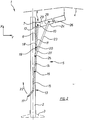
- an umbrella frame 1 which has a vertical mast 2 held in a support leg 3 and a screen 4 indicated by broken lines, which is closed in FIG. 1 and opened in FIG. 2.
- the umbrella frame 1 comprises a guide rail 6 with a slide-shaped sliding part 7, which is in a lower basic position 8 [FIG. 1] and in an upper open position 9 [Fig. 2] is displaceable.
- a push rod 11 is pivotally connected to a first push rod end 12 via a horizontal axis 10.
- a second push rod end 18 is pivotally connected to an opening bracket end 19 opposite the handle 17 via a horizontal axis 20, the push rod being somewhat longer than a first lever side 14 of the opening bracket 13.
- the opening bracket 13 is offset as a two-sided lever with a first lever side 14 and a second lever side 15 in its central region via a horizontal axis 16 to the guide rail 6, pivotally mounted off-center on the mast 2.
- the opening bracket 13 is designed as a U-shaped bracket that runs with two long U-legs as lever parts on both sides of the mast 2.
- a handle 17 is formed as a crosspiece of the U-shaped opening bracket 13.
- the opening bracket 13 is pivotally connected in the region between the horizontal axis 16 and the horizontal axis 20 via a horizontal axis 25 to a first end 27 of a connecting rod 23.
- a second end 28 of the connecting rod 23 is pivotally connected to the boom 24 via a horizontal axis 26, the horizontal axis 26 being arranged above the horizontal axis 10 in the position of FIG. 1.
- Fig. 1 the screen 4 is closed, the sliding part 7 is in the lower basic position 8.
- the push rod 11 points downwards and the opening bracket 13 with the second lever side 15 obliquely upwards.
- the handle 17 is pivoted to the mast 2 in an upper position.
- the handle 17 is pivoted in a semicircular movement [arrow 21 in FIG. 1] down to the mast 2.
- the sliding part 7 is moved by the toggle lever arrangement of the opening bracket 13 and push rod 11 in the direction of its upper position 9.
- the horizontal axis 25, which pivotably connects the connecting rod 23 and the opening bracket 13, describes a circular path and thus does not cause a pure displacement of the connecting rod 23 in the X direction, but at the same time also a lateral displacement of the upper end 28 of the connecting rod 23 in the Y- Direction [cf. the Cartesian coordinate system in FIGS. 1 and 2].
- the toggle lever arrangement consisting of the opening bracket 13 and the push rod 11 is essentially stretched, which results in self-locking, the arrangement being additionally supported by the connecting rod 23 acting as a support strut.
- This arrangement can also be supplemented with a detachable safety device [not shown].
- the opening bracket 13 is finally returned to the starting position corresponding to FIG. 1 in a semicircular manner via the handle 17 [arrow 22 in FIG. 2].
Landscapes
- Walking Sticks, Umbrellas, And Fans (AREA)
- Tents Or Canopies (AREA)
Applications Claiming Priority (2)
| Application Number | Priority Date | Filing Date | Title |
|---|---|---|---|
| DE1996116478 DE19616478C2 (de) | 1996-04-25 | 1996-04-25 | Schirmgestell für einen Großschirm |
| DE19616478 | 1996-04-25 |
Publications (2)
| Publication Number | Publication Date |
|---|---|
| EP0803209A2 true EP0803209A2 (fr) | 1997-10-29 |
| EP0803209A3 EP0803209A3 (fr) | 1999-11-03 |
Family
ID=7792387
Family Applications (1)
| Application Number | Title | Priority Date | Filing Date |
|---|---|---|---|
| EP97104371A Withdrawn EP0803209A3 (fr) | 1996-04-25 | 1997-03-14 | Armature pour parasol de grande taille |
Country Status (2)
| Country | Link |
|---|---|
| EP (1) | EP0803209A3 (fr) |
| DE (1) | DE19616478C2 (fr) |
Cited By (1)
| Publication number | Priority date | Publication date | Assignee | Title |
|---|---|---|---|---|
| EP1042973A1 (fr) * | 1999-04-06 | 2000-10-11 | COLLET, Jean | Parasol et son dispositif d'aide au déploiement et reploiement |
Family Cites Families (6)
| Publication number | Priority date | Publication date | Assignee | Title |
|---|---|---|---|---|
| DE500631C (de) * | 1928-11-09 | 1930-06-24 | Sanner & Co W | Einen Kniehebel aufweisende Spannvorrichtung fuer Grossschirme |
| DE517853C (de) * | 1930-07-15 | 1931-02-11 | Bremshey & Co | Grossschirm |
| AT338452B (de) * | 1975-08-07 | 1977-08-25 | Wuster Heinrich | Schirm, insbesondere gartenschirm |
| AU8333982A (en) * | 1981-04-23 | 1982-11-04 | Collet, Jean | Protective shelter, such as a parasol, with an offset support |
| DE3307718A1 (de) * | 1983-03-04 | 1984-09-06 | Kortenbach & Rauh Kg, 5650 Solingen | Standschirm mit einer vertikalen standsaeule |
| NL8900603A (nl) * | 1989-03-13 | 1990-10-01 | Nijkamp Bv | Vouwbaar scherm. |
-
1996
- 1996-04-25 DE DE1996116478 patent/DE19616478C2/de not_active Expired - Fee Related
-
1997
- 1997-03-14 EP EP97104371A patent/EP0803209A3/fr not_active Withdrawn
Cited By (2)
| Publication number | Priority date | Publication date | Assignee | Title |
|---|---|---|---|---|
| EP1042973A1 (fr) * | 1999-04-06 | 2000-10-11 | COLLET, Jean | Parasol et son dispositif d'aide au déploiement et reploiement |
| FR2792022A1 (fr) * | 1999-04-06 | 2000-10-13 | Jean Collet | Parasol et son dispositif d'aide au deploiement et reploiement |
Also Published As
| Publication number | Publication date |
|---|---|
| DE19616478A1 (de) | 1997-11-06 |
| EP0803209A3 (fr) | 1999-11-03 |
| DE19616478C2 (de) | 1999-03-18 |
Similar Documents
| Publication | Publication Date | Title |
|---|---|---|
| EP0790013B1 (fr) | Parasol | |
| DE3512201C2 (fr) | ||
| WO2008135014A1 (fr) | Élément de protection | |
| CH650059A5 (de) | Dachflaechenfenster. | |
| EP1302120B1 (fr) | Support de cadre pliable pour une tente, un écran ou analogue avec un stand central | |
| DE3129900C2 (de) | Hebeschiebedach für Kraftfahrzeuge | |
| EP0372398A2 (fr) | Pupitre de lecture | |
| CH669799A5 (fr) | ||
| EP0984708A1 (fr) | Parasol | |
| DE2353967B2 (de) | Schirm, insbesondere Gartenschirm | |
| DE19616478C2 (de) | Schirmgestell für einen Großschirm | |
| DE19647271A1 (de) | Klappbare Rückenlehne für Kraftfahrzeugsitze | |
| DE4122447A1 (de) | Vorrichtung zum betaetigen einer bremse eines kraftfahrzeugs | |
| DE10221501B4 (de) | Fahrzeugdach | |
| DE3341988C1 (de) | Ausstellvorrichtung fuer Fahrzeughebedaecher | |
| EP1892136A1 (fr) | Cabriolet doté de deux arceaux de sécurité mutuellement opposés et d'un pare-vent | |
| DE10304391B3 (de) | Standschirm | |
| DE10251107B4 (de) | Vorrichtung zur Arretierung eines linear beweglichen Elements an einem ortsfesten Gegenstand im Kraftfahrzeug- und Nutzfahrzeugbereich | |
| DE102019131985A1 (de) | Mobiler Leichtbau-Scherenhubtisch | |
| DE4022150C1 (en) | Drive for folding vehicle roof - has bracket to load spring when direction of movement is reversed | |
| DE4326122C2 (de) | Manuelle Betätigungsvorrichtung für eine Verriegelung oder einen Antrieb eines Kraftfahrzeugsitzes | |
| EP0802748A1 (fr) | Dispositif permettant de moduler la hauteur et/ou l'inclinaison du plateau d'une table | |
| DE10204220A1 (de) | Automatischer Schirm | |
| DE102004007175B4 (de) | Höhenverstellbare Stützvorrichtung | |
| DE1938042C3 (de) | Befestigungsvorrichtung für Sonnenblenden und Dachluken an Fahrzeugen oder ähnliche Teile |
Legal Events
| Date | Code | Title | Description |
|---|---|---|---|
| PUAI | Public reference made under article 153(3) epc to a published international application that has entered the european phase |
Free format text: ORIGINAL CODE: 0009012 |
|
| AK | Designated contracting states |
Kind code of ref document: A2 Designated state(s): AT CH DE FR IT LI NL |
|
| PUAL | Search report despatched |
Free format text: ORIGINAL CODE: 0009013 |
|
| AK | Designated contracting states |
Kind code of ref document: A3 Designated state(s): AT CH DE FR IT LI NL |
|
| STAA | Information on the status of an ep patent application or granted ep patent |
Free format text: STATUS: THE APPLICATION IS DEEMED TO BE WITHDRAWN |
|
| 18D | Application deemed to be withdrawn |
Effective date: 20000504 |