EP0803209A2 - Frame for over-sized sunshade - Google Patents
Frame for over-sized sunshade Download PDFInfo
- Publication number
- EP0803209A2 EP0803209A2 EP97104371A EP97104371A EP0803209A2 EP 0803209 A2 EP0803209 A2 EP 0803209A2 EP 97104371 A EP97104371 A EP 97104371A EP 97104371 A EP97104371 A EP 97104371A EP 0803209 A2 EP0803209 A2 EP 0803209A2
- Authority
- EP
- European Patent Office
- Prior art keywords
- mast
- sliding part
- umbrella
- horizontal axis
- push rod
- Prior art date
- Legal status (The legal status is an assumption and is not a legal conclusion. Google has not performed a legal analysis and makes no representation as to the accuracy of the status listed.)
- Withdrawn
Links
Images

Classifications
-
- A—HUMAN NECESSITIES
- A45—HAND OR TRAVELLING ARTICLES
- A45B—WALKING STICKS; UMBRELLAS; LADIES' OR LIKE FANS
- A45B23/00—Other umbrellas
-
- A—HUMAN NECESSITIES
- A45—HAND OR TRAVELLING ARTICLES
- A45B—WALKING STICKS; UMBRELLAS; LADIES' OR LIKE FANS
- A45B25/00—Details of umbrellas
- A45B25/14—Devices for opening and for closing umbrellas
-
- A—HUMAN NECESSITIES
- A45—HAND OR TRAVELLING ARTICLES
- A45B—WALKING STICKS; UMBRELLAS; LADIES' OR LIKE FANS
- A45B23/00—Other umbrellas
- A45B2023/0012—Ground supported umbrellas or sunshades on a single post, e.g. resting in or on a surface there below
-
- A—HUMAN NECESSITIES
- A45—HAND OR TRAVELLING ARTICLES
- A45B—WALKING STICKS; UMBRELLAS; LADIES' OR LIKE FANS
- A45B23/00—Other umbrellas
- A45B2023/0031—Cantilever umbrellas or sunshades with a support arm
- A45B2023/0037—Cantilever umbrellas or sunshades with a support arm the support arm being attached to the stick or to the crown, the canopy being suspended there below
Definitions
- the invention relates to an umbrella frame for a large umbrella according to the preamble of claim 1.
- Large umbrellas are generally known in a variety of embodiments. Large umbrellas in particular are manufactured in the traditional way with a central central mast. In many known umbrella constructions, an opening or adjustment of an umbrella is effected in that a sliding part on the mast is moved from a lower basic position to an upper position, which usually corresponds to the open position of the umbrella, using an actuating force.
- Such a sliding part on a central mast of a large umbrella can be implemented in a manner similar to that of small hand-held umbrellas by means of a sliding sleeve that surrounds the mast, struts of the umbrella rod being connected in a known manner to the sliding sleeve.
- the toggle lever arrangement is formed by a push rod and an opening bracket.
- a first push rod end is pivotally connected to the sliding part about a horizontal axis and the opening bracket is pivotally mounted in a central region on the mast about a horizontal axis.
- one opening bracket end is pivotally connected to the second push rod end and the other opening bracket end is designed as a handle.
- the position of the push rod is directed downwards by a closed toggle lever, while in the upper open position of the sliding part an essentially extended position between the push rod and opening bracket is set by an extended toggle lever.
- a center mast umbrella with a one-sided toggle lever arrangement is also described. Furthermore, from AT 338 452 a center mast umbrella is known, in which the roof is opened by means of a lever hinged to the umbrella stick via a rope. One end of the rope is guided over a roller mounted on the lever and the other end of the rope is attached to the umbrella stick.
- the central mast which corresponds to the traditional construction, limits the available space under a large umbrella.
- side mast screens are used in which a side, adjustable boom is articulated on a mast structure, at the free end of which the screen is attached.
- the object of the invention is therefore to provide a simply constructed and inexpensive umbrella frame for a large umbrella designed as a side mast umbrella, so that the opening and adjustment of a screen is possible quickly and with little effort and good function.
- a first end of a connecting rod is pivotally connected to the opening bracket about a horizontal axis.
- a second end of the connecting rod is also connected to a boom so as to be pivotable about a horizontal axis.
- the lower end of the boom is pivotally connected to a sliding part about a horizontal axis.
- the lower basic position of the sliding part is determined by a closed toggle lever with a downward position of the push rod and the connecting rod running essentially parallel to the mast axis.
- the boom can be pivoted about the horizontal axis by means of the connecting rod due to the positive guidance of the lower end in the linear guide device.
- the upper open position of the sliding part is determined by an extended toggle lever with an essentially extended position between the push rod and the opening bracket and by the connecting rod which projects laterally from the opening bracket and does not run parallel to the mast axis and supports the boom.
- a connecting rod is therefore additionally provided, which is articulated both on the opening bracket and on a boom coupled to the guide part.
- the connecting rod which is preferably made of a light metal, is deflected in particular with its upper end both upwards and to the side when the screen is opened, as a result of which the boom is pivoted into a projecting position.
- the toggle lever arrangement used is largely matched to the conditions of the screen actuation in its force-transmitting effect. Obviously, a very high amount of force is required when the screen is actuated when the boom has already been swung far out in the direction of the open position and its weight must therefore be fully supported. Another force peak occurs immediately in the open position when the fabric covering the screen has to be stretched.
- this effort occurs in the last upper sliding area of the sliding part. Due to the toggle lever function according to the invention, however, this high actuation force can be applied by a person without great effort, even with side masts, by stretching the toggle lever.
- the proposed toggle lever arrangement thus interacts optimally with the force requirements that change over the adjustment path for a quick, comfortable and energy-saving manual operation of a side mast screen.
- This toggle lever arrangement connected with a connecting rod can also be inexpensively manufactured with a few components which can be produced inexpensively.
- the simple construction therefore ensures a high level of functional reliability with a long service life. Maintenance and care is not necessary.
- the opening bracket is designed as a two-sided lever, resulting in a particularly advantageous embodiment of an opening bracket provided with an additional connecting rod.
- the handle is preferably pivoted upward toward the mast in the lower basic position of the sliding part, so that a side mast screen, when the handle is moved downward using the body weight, can be opened and / or adjusted in a force-saving and simple manner. To do this, it is only necessary to follow the handle in a circular arc from its upper starting position pivoted towards the mast to bring it down into a position that is also folded towards the mast. This only required movement can be carried out very quickly.
- the opening bracket can also be designed as a one-sided lever and / or the handle can be pivoted downwards towards the mast in the lower basic position of the sliding part.
- the arrangement is selected according to claim 3 so that there is a sufficient adjustment path and the handle is easily accessible both in the upper and lower positions.
- the toggle lever arrangement according to the invention can be attached to a conventional sliding sleeve of the mast according to claim 4.
- the linear guide device comprises a guide rail and / or guide groove on the side of the mast, into which a guide part engages.
- the guide device can thus be of small dimensions, particularly lightweight and smooth.
- the guide part can engage on the guide rail or guide groove over a certain longitudinal extent, a slide design being expedient.
- the opening bracket is designed as a U-shaped bracket, the bracket is bent in the region of the U-base and the transverse web forms a handle.
- the two long U-legs run to the push rod on both sides of the mast. This enables the opening bracket to be stably supported over both U-legs on the mast.
- this self-locking is released by moving the handle from the lower position upwards, this movement being supported by the restoring forces of the umbrella.
- an actuation path for a swiveling umbrella boom according to claim 9 is made available.
- a connection to this sliding part can be made directly or indirectly, for example by a cable connection.
- an umbrella frame 1 which has a vertical mast 2 held in a support leg 3 and a screen 4 indicated by broken lines, which is closed in FIG. 1 and opened in FIG. 2.
- the umbrella frame 1 comprises a guide rail 6 with a slide-shaped sliding part 7, which is in a lower basic position 8 [FIG. 1] and in an upper open position 9 [Fig. 2] is displaceable.
- a push rod 11 is pivotally connected to a first push rod end 12 via a horizontal axis 10.
- a second push rod end 18 is pivotally connected to an opening bracket end 19 opposite the handle 17 via a horizontal axis 20, the push rod being somewhat longer than a first lever side 14 of the opening bracket 13.
- the opening bracket 13 is offset as a two-sided lever with a first lever side 14 and a second lever side 15 in its central region via a horizontal axis 16 to the guide rail 6, pivotally mounted off-center on the mast 2.
- the opening bracket 13 is designed as a U-shaped bracket that runs with two long U-legs as lever parts on both sides of the mast 2.
- a handle 17 is formed as a crosspiece of the U-shaped opening bracket 13.
- the opening bracket 13 is pivotally connected in the region between the horizontal axis 16 and the horizontal axis 20 via a horizontal axis 25 to a first end 27 of a connecting rod 23.
- a second end 28 of the connecting rod 23 is pivotally connected to the boom 24 via a horizontal axis 26, the horizontal axis 26 being arranged above the horizontal axis 10 in the position of FIG. 1.
- Fig. 1 the screen 4 is closed, the sliding part 7 is in the lower basic position 8.
- the push rod 11 points downwards and the opening bracket 13 with the second lever side 15 obliquely upwards.
- the handle 17 is pivoted to the mast 2 in an upper position.
- the handle 17 is pivoted in a semicircular movement [arrow 21 in FIG. 1] down to the mast 2.
- the sliding part 7 is moved by the toggle lever arrangement of the opening bracket 13 and push rod 11 in the direction of its upper position 9.
- the horizontal axis 25, which pivotably connects the connecting rod 23 and the opening bracket 13, describes a circular path and thus does not cause a pure displacement of the connecting rod 23 in the X direction, but at the same time also a lateral displacement of the upper end 28 of the connecting rod 23 in the Y- Direction [cf. the Cartesian coordinate system in FIGS. 1 and 2].
- the toggle lever arrangement consisting of the opening bracket 13 and the push rod 11 is essentially stretched, which results in self-locking, the arrangement being additionally supported by the connecting rod 23 acting as a support strut.
- This arrangement can also be supplemented with a detachable safety device [not shown].
- the opening bracket 13 is finally returned to the starting position corresponding to FIG. 1 in a semicircular manner via the handle 17 [arrow 22 in FIG. 2].
Landscapes
- Walking Sticks, Umbrellas, And Fans (AREA)
- Tents Or Canopies (AREA)
Abstract
Die Erfindung betrifft ein Schirmgestell für einen Großschirm. Ein als Seitenmastschirm ausgebildeter Großschirm umfaßt eine Mastkonstruktion 2, an der ein seitlicher, verstellbarer Ausleger 24 angelenkt ist, an dessen freiem Ende der Schirm angebracht ist. Entlang des Mastes 2 ist eine lineare Führungseinrichtung 5 mit einem Schiebeteil 7 vorgesehen. Zwischen dem Schiebeteil 7 und dem Mast 2 ist eine Kniehebelanordnung aus einer Schubstange 11 und einem Öffnungsbügel 13 angebracht mit einer Verlängerung des Öffnungsbügels, an der ein Handgriff 17 angeordnet ist. Erfindungsgemäß ist eine Verbindungsstange 23 vorgesehen, die sowohl am Öffnungsbügel 13 als auch an dem mit dem Schiebeteil 7 gekoppelten Ausleger 24 angelenkt ist, so daß der Ausleger 24 beim Öffnen des Schirmes in eine seitlich auskragende Stellung gebracht wird. Damit wird ein einfach aufgebautes, funktionsfähiges und wartungsfreies Schirmgestell für Seitenmastschirme zur Verfügung gestellt, mit dem eine schnelle und kraftsparende Schirmbetätigung möglich ist.
Description
Die Erfindung betrifft ein Schirmgestell für einen Großschirm nach dem Oberbegriff des Anspruchs 1.The invention relates to an umbrella frame for a large umbrella according to the preamble of
Großschirme sind allgemein in einer Mehrzahl von Ausführungsformen bekannt. Insbesondere werden Großschirme in der traditionellen Bauweise mit einem zentralen Mittenmast hergestellt. Bei vielen bekannten Schirmkonstruktionen wird eine Öffnung oder Verstellung eines Schirms dadurch bewirkt, daß ein Schiebeteil am Mast von einer unteren Grundstellung unter Aufwendung einer Betätigungskraft in eine obere Stellung, die üblicherweise der Offenstellung des Schirms entspricht, verschoben wird.Large umbrellas are generally known in a variety of embodiments. Large umbrellas in particular are manufactured in the traditional way with a central central mast. In many known umbrella constructions, an opening or adjustment of an umbrella is effected in that a sliding part on the mast is moved from a lower basic position to an upper position, which usually corresponds to the open position of the umbrella, using an actuating force.
Ein solches Schiebeteil an einem Mittenmast eines Großschirms kann ähnlich wie bei kleinen Handschirmen durch eine den Mast umfassende Schliebemuffe realisiert sein, wobei mit der Schiebemuffe Streben des Schirmgestänges in bekannter Weise verbunden sind.Such a sliding part on a central mast of a large umbrella can be implemented in a manner similar to that of small hand-held umbrellas by means of a sliding sleeve that surrounds the mast, struts of the umbrella rod being connected in a known manner to the sliding sleeve.
Die erheblichen Ausmaße eines Großschirms bedingen allerdings ein großes Gewicht der beweglichen Schirmteile mit langen Hebelwegen. Dies führt dazu, daß ein Aufspannen und Verstellen eines Großschirms und damit eine Verschiebung eines Schiebeteils von unten nach oben am Mast mit erheblichem Kraftaufwand verbunden ist. Eine unmittelbare Verschiebung von Hand ist mühsam und praktisch nur bis zu einer begrenzten Schirmgröße möglich. Es sind daher für größere Schirme kraftverstärkende Einrichtungen bekannt, wie z.B. bei einem gattungsgemäßen Schirmgestell nach der DE-PS 500 631. Dort ist ein Mittenmastschirm mit einer Kniehebelanordnung beschrieben, der ein Schiebeteil umfaßt, das mittels der Kniehebelanordnung entlang eines Mastes von einer unteren Grundstellung in eine obere Offenstellung bewegbar ist, wobei mit dem Schiebeteil Mittel zum Öffnen und/oder Verstellen eines Schirms verbunden sind. Die Kniehebelanordnung wird durch eine Schubstange und einen Öffnungsbügel gebildet. Im einzelnen ist dazu ein erstes Schubstangenende um eine horizontale Achse schwenkbar mit dem Schiebeteil verbunden und der Öffnungsbügel in einem mittleren Bereich am Mast um eine horizontale Achse schwenkbar gelagert. Weiter ist ein Öffnungsbügelende schwenkbar mit dem zweiten Schubstangenende verbunden und das andere Öffnungsbügelende als Handhabe ausgebildet. In der unteren Grundstellung des Schiebeteils ist hier durch einen geschlossenen Kniehebel die Stellung der Schubstange nach unten gerichtet, während in der oberen Offenstellung des Schiebeteils durch einen gestreckten Kniehebel eine im wesentlichen gestreckte Stellung zwischen Schubstange und Öffnungsbügel eingestellt ist.The considerable dimensions of a large umbrella, however, mean that the movable umbrella parts with long leverage are very heavy. This means that a clamping and adjusting a large screen and thus a displacement of a sliding part from the bottom to the top of the mast is associated with considerable effort. An immediate shift by hand is tedious and practically only to a limited extent Umbrella size possible. It is therefore known for larger umbrellas power-boosting devices, such as in a generic umbrella frame according to DE-PS 500 631. There is described a central mast umbrella with a toggle lever arrangement, which comprises a sliding part which by means of the toggle lever arrangement along a mast from a lower basic position in an upper open position is movable, means for opening and / or adjusting a screen being connected to the sliding part. The toggle lever arrangement is formed by a push rod and an opening bracket. In particular, a first push rod end is pivotally connected to the sliding part about a horizontal axis and the opening bracket is pivotally mounted in a central region on the mast about a horizontal axis. Furthermore, one opening bracket end is pivotally connected to the second push rod end and the other opening bracket end is designed as a handle. In the lower basic position of the sliding part, the position of the push rod is directed downwards by a closed toggle lever, while in the upper open position of the sliding part an essentially extended position between the push rod and opening bracket is set by an extended toggle lever.
Aus der DE-PS 517 853 ist ferner ein Mittenmastschirm mit einer einseitigen Kniehebelanordnung beschrieben. Weiter ist aus der AT 338 452 ein Mittenmastschirm bekannt, bei welchem das Öffnen des Daches mittels eines am Schirmstock angelenkten Hebels über ein Seil erfolgt. Dabei ist das eine Seilende über eine am Hebel gelagerte Rolle geführt und das andere Seilende am Schirmstock befestigt.From DE-PS 517 853 a center mast umbrella with a one-sided toggle lever arrangement is also described. Furthermore, from AT 338 452 a center mast umbrella is known, in which the roof is opened by means of a lever hinged to the umbrella stick via a rope. One end of the rope is guided over a roller mounted on the lever and the other end of the rope is attached to the umbrella stick.
Der entsprechend der traditionellen Bauweise jeweils zentrale Mittenmast schränkt allerdings die zur Verfügung stehende freie Fläche unter einem Großschirm ein. Um eine möglichst große freie Fläche unter einem Großschirm zu erhalten, die nicht durch einen Mittenmast behindert ist, werden daher Seitenmastschirme verwendet, bei denen an einer Mastkonstruktion ein seitlicher, verstellbarer Ausleger angelenkt ist, an dessen freiem Ende der Schirm angebracht ist.The central mast, which corresponds to the traditional construction, limits the available space under a large umbrella. In order to obtain the largest possible free area under a large umbrella that is not hampered by a central mast Therefore, side mast screens are used in which a side, adjustable boom is articulated on a mast structure, at the free end of which the screen is attached.
Bei Großschirmen mit einem Seitenmast ist es bekannt [EP 0 091 433 B1, Fig. 59 und 60], ein am Mast geführtes Strebenende eines Auslegers zum Öffnen des Schirms von einer unteren Position in eine obere Position am Mast zu verschieben.In large umbrellas with a side mast it is known [EP 0 091 433 B1, FIGS. 59 and 60] to move a strut end of a boom guided on the mast to open the umbrella from a lower position to an upper position on the mast.
Überwiegend werden an Großschirmen mit Seitenmast für die Schirmbetätigung Anordnungen aus Seilen und Seilwinden verwendet. Eine derartige Anordnung ist aus der EP 03 87 965 A1 bekannt. Hierbei ist im Inneren eines Mastes ein Seil über Umlenkrollen geführt, wobei in einem Seilbereich ein mit einem Ausleger fest verbundenes Gleitelement fest angeordnet ist. Durch das Betätigen einer eine Seilumlenkrolle antreibenden Handkurbel wird das Gleitelement von einer unteren Stellung in eine obere Stellung verfahren, wodurch der Ausleger ausgefahren wird. Solche Konstruktionen mit Seilen und Seilwinden sind relativ aufwendig hinsichtlich der erforderlichen Seilführungen. Zudem werden Großschirme regelmäßig im Freien verwendet, so daß sowohl das Seilmaterial als auch die Seilwinden korrosionsbeständig, hochwertig und damit relativ teuer sind. Weiter ist eine solche komplizierte Seilanordnung störanfällig. Durch die Kraftumsetzung in der Seilwinde sind bei einer Verstellung große Seilwege und damit viele Umdrehungen der Seilwinde erforderlich. Dadurch ist eine Betätigung zwar nicht mehr kraftaufwendig aber nur mit größerem Zeitaufwand möglich. Im gewerblichen Bereich, wenn beispielsweise eine Person eine Mehrzahl von Großschirmen aufzuspannen hat, ist dies ein merklicher Kostenfaktor. Die Betätigungskurbeln sind von den Seilwinden zum Teil abnehmbar und müssen aufwendig getrennt verstaut und bereitgehalten werden.Arrangements made of ropes and winches are mainly used on large umbrellas with side masts for the umbrella actuation. Such an arrangement is known from EP 03 87 965 A1. In this case, a rope is guided over deflection pulleys inside a mast, a sliding element firmly connected to a boom being fixedly arranged in a rope area. By actuating a hand crank that drives a rope deflection roller, the sliding element is moved from a lower position to an upper position, as a result of which the boom is extended. Such constructions with ropes and winches are relatively complex in terms of the required rope guides. In addition, large umbrellas are regularly used outdoors, so that both the rope material and the winches are corrosion-resistant, high quality and therefore relatively expensive. Furthermore, such a complicated cable arrangement is prone to failure. Due to the power conversion in the cable winch, long cable paths and thus many revolutions of the cable winch are required for adjustment. As a result, actuation is no longer energy-intensive but only possible with a greater expenditure of time. In the commercial sector, for example when a person has to open a large number of large screens, this is a noticeable cost factor. The operating cranks can be partially removed from the cable winches and have to be stowed away separately and kept ready.
Aufgabe der Erfindung ist es daher, ein einfach aufgebautes und kostengünstiges Schirmgestell für einen als Seitenmastschirm ausgebildeten Großschirm zu schaffen, so daß das Öffnen und Verstellen eines Schirms schnell und mit geringem Kraftaufwand bei guter Funktion möglich ist.The object of the invention is therefore to provide a simply constructed and inexpensive umbrella frame for a large umbrella designed as a side mast umbrella, so that the opening and adjustment of a screen is possible quickly and with little effort and good function.
Diese Aufgabe wird mit den Merkmalen des Anspruchs 1 gelöst.This object is achieved with the features of
Gemäß Anspruch 1 ist ein erstes Ende einer Verbindungsstange mit dem Öffnungsbügel um eine horizontale Achse schwenkbar verbunden. Ein zweites Ende der Verbindungsstange ist mit einem Ausleger ebenfalls um eine horizontale Achse schwenkbar verbunden. Weiter ist mit dem Schiebeteil das untere Ende des Auslegers um eine horizontale Achse schwenkbar verbunden. Die untere Grundstellung des Schiebeteils ist durch einen geschlossenen Kniehebel mit einer nach unten gerichteten Stellung der Schubstange und der im wesentlichen parallel zur Mastachse verlaufenden Verbindungsstange bestimmt. Bei der Öffnung des Schirmgestells ist der Ausleger mittels der Verbindungsstange aufgrund der Zwangsführung des unteren Endes in der linearen Führungseinrichtung um die horizontale Achse verschwenkbar. Dadurch ist die obere Offenstellung des Schiebeteils durch einen gestreckten Kniehebel mit einer im wesentlichen gestreckten Stellung zwischen Schubstange und Öffnungsbügel und durch die vom Öffnungsbügel seitlich wegragende, nicht parallel zur Mastachse verlaufende, den Ausleger abstützende Verbindungsstange bestimmt.According to
Bei dieser erfindungsgemäßen Kniehebelanordnung ist also zusätzlich eine Verbindungsstange vorgesehen, die sowohl am Öffnungsbügel als auch an einem mit dem Führungsteil gekoppelten Ausleger angelenkt ist. Die bevorzugt aus einem Leichtmetall hergestellte Verbindungsstange wird beim Öffnen des Schirmes insbesondere mit ihrem oberen Ende sowohl nach oben als auch zur Seite hin ausgelenkt, wodurch der Ausleger in eine auskragende Stellung verschwenkt wird. Die verwendete Kniehebelanordnung ist dabei in ihrer kraftübertragenden Wirkung weitgehend auf die Gegebenheiten der Schirmbetätigung abgestimmt. Ersichtlich ist nämlich bei einer Schirmbetätigung erst ein sehr hoher Kraftaufwand erforderlich, wenn der Ausleger bereits weit in Richtung der geöffneten Stellung ausgeschwenkt ist und damit sein Gewicht voll abzustützen ist. Eine weitere Kraftspitze tritt unmittelbar zusätzlich an der geöffneten Stellung auf, wenn die Tuchbespannung des Schirms gespannt werden muß. Entsprechend tritt dieser Kraftaufwand im letzten oberen Schiebebereich des Schiebeteils auf. Durch die erfindungsgemäße Kniehebelfunktion ist jedoch diese hohe Betätigungskraft durch Streckung des Kniehebels von einer Person ohne große Kraftanstrengung auch bei Seitenmastschirmen aufbringbar. Die vorgeschlagene Kniehebelanordnung wirkt somit optimal mit den sich über den Verstellweg ändernden Kraftanforderungen für eine schnelle, bequeme und kraftsparende Handbetätigung eines Seitenmastschirms zusammen.In this toggle lever arrangement according to the invention, a connecting rod is therefore additionally provided, which is articulated both on the opening bracket and on a boom coupled to the guide part. The connecting rod, which is preferably made of a light metal, is deflected in particular with its upper end both upwards and to the side when the screen is opened, as a result of which the boom is pivoted into a projecting position. The toggle lever arrangement used is largely matched to the conditions of the screen actuation in its force-transmitting effect. Obviously, a very high amount of force is required when the screen is actuated when the boom has already been swung far out in the direction of the open position and its weight must therefore be fully supported. Another force peak occurs immediately in the open position when the fabric covering the screen has to be stretched. Accordingly, this effort occurs in the last upper sliding area of the sliding part. Due to the toggle lever function according to the invention, however, this high actuation force can be applied by a person without great effort, even with side masts, by stretching the toggle lever. The proposed toggle lever arrangement thus interacts optimally with the force requirements that change over the adjustment path for a quick, comfortable and energy-saving manual operation of a side mast screen.
Diese mit einer Verbindungsstange verbundene Kniehebelanordnung ist ferner mit wenigen, kostengünstig herstellbaren Bauteilen preisgünstig herzustellen. Durch die einfache Konstruktion ist somit eine hohe Funktionssicherheit mit großer Lebensdauer gegeben. Eine Wartung und Pflege ist nicht erforderlich.This toggle lever arrangement connected with a connecting rod can also be inexpensively manufactured with a few components which can be produced inexpensively. The simple construction therefore ensures a high level of functional reliability with a long service life. Maintenance and care is not necessary.
Nach Anspruch 2 ist der Öffnungsbügel als zweiseitiger Hebel ausgeführt, wodurch sich eine besonders vorteilhafte Ausführungsform eines mit einer zusätzlichen Verbindungsstange versehenen Öffnungsbügels ergibt. Bevorzugt ist hierbei die Handhabe in der unteren Grundstellung des Schiebeteils nach oben zum Mast hin geschwenkt, so daß ein Seitenmastschirm, wenn die Handhabe unter Einsatz des Körpergewichts nach unten bewegt wird, auf kraftsparende und einfache Weise zu öffnen und/oder zu verstellen ist. Dazu ist es lediglich erforderlich, die Handhabe von ihrer oberen an den Mast hin verschwenkten Ausgangsstellung in einem Kreisbogen nach unten in eine ebenfalls zum Mast hin geklappte Stellung zu bringen. Diese einzig erforderliche Bewegung ist sehr schnell durchführbar. In einer alternativen Ausführungsform kann der Öffnungsbügel auch als einseitiger Hebel ausgeführt sein und/oder die Handhabe in der unteren Grundstellung des Schiebeteils nach unten zum Mast hin verschwenkt sein.According to
Zweckmäßig ist nach Anspruch 3 die Anordnung so gewählt, daß ein ausreichender Verstellweg vorliegt und dabei die Handhabe sowohl in der oberen als auch unteren Stellung bequem erreichbar ist.Appropriately, the arrangement is selected according to
Die erfindungsgemäße Kniehebelanordnung kann nach Anspruch 4 an einer herkömmlichen Schiebemuffe des Mastes angebracht sein. In einer bevorzugten Ausführungsform nach Anspruch 5 umfaßt die lineare Führungseinrichtung jedoch eine Führungsschiene und/oder Führungsnut seitlich am Mast, in die ein Führungsteil eingreift. Damit kann die Führungseinrichtung mit geringen Ausmaßen, besonders gewichtsgünstig und leichtgängig ausgeführt sein. Das Führungsteil kann hier über eine gewisse Längserstreckung an der Führungsschiene oder Führungsnut eingreifen, wobei eine Schlittenausführung zweckmäßig ist.The toggle lever arrangement according to the invention can be attached to a conventional sliding sleeve of the mast according to
Eine zweckmäßige Konstruktion ergibt sich mit den Merkmalen nach Anspruch 6 dadurch, daß der Öffnungsbügel als U-förmiger Bügel ausgeführt ist, wobei der Bügel im Bereich der U-Basis abgekröpft ist und der querverlaufende Steg einen Handgriff bildet. Die zwei langen U-Schenkel verlaufen zu beiden Seiten des Mastes zur Schubstahge hin. Dadurch ist eine stabile Lagerung des Öffnungsbügels über beide U-Schenkel am Mast möglich.A useful construction results with the features of
Besonders vorteilhaft ergibt sich nach Anspruch 7 eine Selbsthemmung der Kniehebelanordnung in der gestreckten Stellung gegen die rückstellenden Kräfte des Schirms, insbesondere dann, wenn das Kniegelenk in der Offenstellung etwas über die gestreckte Stellung hinaus am Mast abgestützt ist.Particularly advantageous results in a self-locking of the toggle lever arrangement in the extended position against the restoring forces of the screen, especially when the knee joint is supported somewhat beyond the extended position on the mast in the open position.
Zum Schließen des Schirms wird diese Selbsthemmung durch eine Bewegung der Handhabe von der unteren Stellung nach oben wieder aufgehoben, wobei diese Bewegung durch die rückstellenden Kräfte des Schirms unterstützt wird.To close the umbrella, this self-locking is released by moving the handle from the lower position upwards, this movement being supported by the restoring forces of the umbrella.
Trotz der Selbsthemmung ist es nach Anspruch 8 zweckmäßig eine Sicherung für diese Stellung anzubringen. Diese Sicherung kann beispielsweise im gewerblichen Bereich absperrbar sein und verhindert ein unbefugtes oder unabsichtliches Schließen des Schirms.Despite the self-locking, it is expedient to attach a safety device for this position. This security can be locked, for example, in the commercial sector and prevents unauthorized or unintentional closing of the screen.
Mit der Verstellung des Schiebeteils wird ein Betätigungsweg für einen schwenkbaren Schirmausleger entsprechend Anspruch 9 zur Verfügung gestellt. Eine Verbindung mit diesem Schiebeteil kann unmittelbar oder mittelbar, beispielsweise durch eine Seilverbindung erfolgen.With the adjustment of the sliding part, an actuation path for a swiveling umbrella boom according to claim 9 is made available. A connection to this sliding part can be made directly or indirectly, for example by a cable connection.
Anhand einer Zeichnung wird ein Ausführungsbeispiel der Erfindung mit weiteren Einzelheiten, Merkmalen und Vorteilen näher erläutert.An exemplary embodiment of the invention with further details, features and advantages is explained in more detail with reference to a drawing.
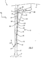
Es zeigen:
- Fig. 1
- eine Seitenansicht eines Schirmgestells mit einem schematisch angedeuteten Schirm in dessen Geschlossenstellung, und
- Fig. 2
- das Schirmgestell nach Fig. 1 in der Offenstellung des Schirms
- Fig. 1
- a side view of an umbrella frame with a schematically indicated umbrella in its closed position, and
- Fig. 2
- 1 in the open position of the screen
Bei der Ausführungsform nach den Fig. 1 und 2 ist ein Schirmgestell 1 dargestellt, das einen in einem Stützfuß 3 gehaltenen, vertikalen Mast 2 und einen strichliert angedeuteten Schirm 4 aufweist, der in Fig. 1 geschlossen und in Fig. 2 geöffnet ist.In the embodiment according to FIGS. 1 and 2, an
Das Schirmgestell 1 umfaßt als lineare Führungseinrichtung 5, eine Führungsschiene 6 mit einem schlittenförmigen Schiebeteil 7, das in eine untere Grundstellung 8 [Fig. 1] und in eine obere Offenstellung 9 [Fig. 2] verschiebbar ist.As a
Mit dem Schiebeteil 7 ist über eine horizontale Achse 10 eine Schubstange 11 mit einem ersten Schubstangenende 12 schwenkbar verbunden.With the sliding
Ebenfalls ist über die horizontale Achse 10 ein unteres Ende 29 eines Auslegers 24, der in der Darstellung der Fig. 1 und 2 lediglich teilweise dargestellt ist, mit dem Schiebeteil 7 schwenkbar verbunden.Likewise, a
Ein zweites Schubstangenende 18 ist mit einem dem Handgriff 17 gegenüberliegenden Öffnungsbügelende 19 über eine horizontale Achse 20 schwenkbar verbunden, wobei die Schubstange etwas länger als eine erste Hebelseite 14 des Öffnungsbügels 13 ist.A second
Der Öffnungsbügel 13 ist als zweiseitiger Hebel mit einer ersten Hebelseite 14 und einer zweiten Hebelseite 15 in seinem mittleren Bereich über eine horizontale Achse 16 zur Führungsschiene 6 hin versetzt, außermittig am Mast 2 schwenkbar gelagert. Der Öffnungsbügel 13 ist dabei als U-förmiger Bügel ausgebildet, der mit zwei langen U-Schenkeln als Hebelteile zu beiden Seiten des Mastes 2 verläuft. Am freien Ende der zweiten Hebelseite 15 ist ein Handgriff 17 als Quersteg des U-förmigen Öffnungsbügels 13 geformt.The
Ferner ist der Öffnungsbügel 13 im Bereich zwischen der horizontalen Achse 16 und der horizontalen Achse 20 über eine horizontale Achse 25 mit einem ersten Ende 27 einer Verbindungsstange 23 schwenkbar verbunden.Furthermore, the
Ein zweites Ende 28 der Verbindungsstange 23 ist über eine horizontale Achse 26 mit dem Ausleger 24 schwenkbar verbunden, wobei die horizontale Achse 26 in der Stellung der Fig. 1 über der horizontalen Achse 10 liegend angeordnet ist.A
Die dargestellte Anordnung hat folgende Funktion:The arrangement shown has the following function:
In Fig. 1 ist der Schirm 4 geschlossen, wobei das Schiebeteil 7 in der unteren Grundstellung 8 steht. Dabei weist die Schubstange 11 nach unten und der Öffnungsbügel 13 mit der zweiten Hebelseite 15 schräg nach oben. Der Handgriff 17 ist an den Mast 2 in einer oberen Stellung geschwenkt.In Fig. 1, the
Zum Öffnen des Schirms wird der Handgriff 17 in einer Halbkreisbewegung [Pfeil 21 in Fig. 1] nach unten zum Mast 2 hin verschwenkt. Dabei wird das Schiebeteil 7 durch die Kniehebelanordnung aus Öffnungsbügel 13 und Schubstange 11 in Richtung auf seine obere Stellung 9 hin verschoben. Die horizontale Achse 25, die die Verbindungsstange 23 und den Öffnungsbügel 13 schwenkbar verbindet, beschreibt dabei eine Kreisbahn und bewirkt dadurch keine reine Verschiebung der Verbindungsstange 23 in X-Richtung, sondern gleichzeitig auch eine seitliche Verschiebung des oberen Endes 28 der Verbindungsstange 23 in Y-Richtung [vgl. dazu das kartesische Koordinatensystem in den Fig. 1 und 2]. Durch diese Verschiebung des mit dem Ausleger 24 über die horizontale Achse 26 schwenkbar verbundenen oberen Endes 28 der Verbindungsstange 23 in sowohl X- als auch Y-Richtung wird der Ausleger 24, der mit seinem unteren Ende 29 in der linearen Führungseinrichtung 5 zwangsgeführt wird, aus der in der unteren Grundstellung im wesentlichen parallel zur Mastachse ausgerichteten Stellung heraus um die horizontale Achse 10 in die in der oberen Offenstellung der Fig. 2 dargestellte, auskragende Stellung verschwenkt. Der Öffnungswinkel zwischen dem Mast 2 und dem Ausleger 24 in der oberen Offenstellung ist dabei durch den im wesentlichen senkrechten Abstand zwischen der horizontalen Achse 20 und der horizontalen Achse 25 festgelegt.To open the screen, the
In dieser oberen Offenstellung ist die Kniehebelanordnung aus Öffnungsbügel 13 und Schubstange 11 im wesentlichen gestreckt, was eine Selbsthemmung zur Folge hat, wobei die Anordnung durch die als Stützstrebe wirkende Verbindungsstange 23 eine zusätzliche Abstützung erfährt. Diese Anordnung ist zudem um eine lösbare Sicherheitseinrichtung ergänzbar [nicht dargestellt].In this upper open position, the toggle lever arrangement consisting of the
Zum Schließen des Schirms 4 wird der Öffnungsbügel 13 schließlich über den Handgriff 17 wieder halbkreisförmig in die Ausgangslage entsprechend Fig. 1 zurückgeführt [Pfeil 22 in Fig. 2].To close the
Claims (9)
wobei mit dem Schiebeteil [7] eine Schubstange [11] mit ihrem ersten Schubstangenende [12] um eine horizontale Achse [10] schwenkbar verbunden ist,
dadurch gekennzeichnet,
a push rod [11] having its first push rod end [12] pivotably connected to a sliding axis [10] about a horizontal axis [10],
characterized,
Applications Claiming Priority (2)
| Application Number | Priority Date | Filing Date | Title |
|---|---|---|---|
| DE1996116478 DE19616478C2 (en) | 1996-04-25 | 1996-04-25 | Umbrella frame for a large umbrella |
| DE19616478 | 1996-04-25 |
Publications (2)
| Publication Number | Publication Date |
|---|---|
| EP0803209A2 true EP0803209A2 (en) | 1997-10-29 |
| EP0803209A3 EP0803209A3 (en) | 1999-11-03 |
Family
ID=7792387
Family Applications (1)
| Application Number | Title | Priority Date | Filing Date |
|---|---|---|---|
| EP97104371A Withdrawn EP0803209A3 (en) | 1996-04-25 | 1997-03-14 | Frame for over-sized sunshade |
Country Status (2)
| Country | Link |
|---|---|
| EP (1) | EP0803209A3 (en) |
| DE (1) | DE19616478C2 (en) |
Cited By (1)
| Publication number | Priority date | Publication date | Assignee | Title |
|---|---|---|---|---|
| EP1042973A1 (en) * | 1999-04-06 | 2000-10-11 | COLLET, Jean | Sunshade and device to assist for opening and closing |
Family Cites Families (6)
| Publication number | Priority date | Publication date | Assignee | Title |
|---|---|---|---|---|
| DE500631C (en) * | 1928-11-09 | 1930-06-24 | Sanner & Co W | Clamping device for large umbrellas with a toggle lever |
| DE517853C (en) * | 1930-07-15 | 1931-02-11 | Bremshey & Co | Large umbrella |
| AT338452B (en) * | 1975-08-07 | 1977-08-25 | Wuster Heinrich | UMBRELLA, IN PARTICULAR GARDEN UMBRELLA |
| AU8333982A (en) * | 1981-04-23 | 1982-11-04 | Collet, Jean | Protective shelter, such as a parasol, with an offset support |
| DE3307718A1 (en) * | 1983-03-04 | 1984-09-06 | Kortenbach & Rauh Kg, 5650 Solingen | Standing umbrella with a vertical standing column |
| NL8900603A (en) * | 1989-03-13 | 1990-10-01 | Nijkamp Bv | FOLDABLE SCREEN. |
-
1996
- 1996-04-25 DE DE1996116478 patent/DE19616478C2/en not_active Expired - Fee Related
-
1997
- 1997-03-14 EP EP97104371A patent/EP0803209A3/en not_active Withdrawn
Cited By (2)
| Publication number | Priority date | Publication date | Assignee | Title |
|---|---|---|---|---|
| EP1042973A1 (en) * | 1999-04-06 | 2000-10-11 | COLLET, Jean | Sunshade and device to assist for opening and closing |
| FR2792022A1 (en) * | 1999-04-06 | 2000-10-13 | Jean Collet | PARASOL AND ITS DEPLOYMENT AND REPLOYMENT ASSISTANCE DEVICE |
Also Published As
| Publication number | Publication date |
|---|---|
| DE19616478A1 (en) | 1997-11-06 |
| EP0803209A3 (en) | 1999-11-03 |
| DE19616478C2 (en) | 1999-03-18 |
Similar Documents
| Publication | Publication Date | Title |
|---|---|---|
| EP0790013B1 (en) | Sunshade | |
| DE3512201C2 (en) | ||
| WO2008135014A1 (en) | Umbrella | |
| CH650059A5 (en) | ROOF AREA WINDOW. | |
| EP1302120B1 (en) | Framework rack for a foldable tent, screen or the like with a central stand | |
| DE3129900C2 (en) | Lifting and sliding roof for motor vehicles | |
| EP0372398A2 (en) | Pulpit | |
| CH669799A5 (en) | ||
| EP0984708A1 (en) | Upright shade | |
| DE2353967B2 (en) | Umbrella, in particular garden umbrella | |
| DE19616478C2 (en) | Umbrella frame for a large umbrella | |
| DE19647271A1 (en) | Folding seat back for motor vehicle seat | |
| DE4122447A1 (en) | Hand brake actuation appts. for road vehicle - is aided by combination of cable compensating spring force and servo spring force that has line of action changed to give snap action | |
| DE10221501B4 (en) | vehicle roof | |
| DE3341988C1 (en) | Display device for vehicle lifting roofs | |
| EP1892136A1 (en) | Convertible with two roll bars with a separation distance and a wind breaker | |
| DE10304391B3 (en) | standing umbrella | |
| DE10251107B4 (en) | Device for locking a linearly movable element on a stationary object in the motor vehicle and commercial vehicle sector | |
| DE102019131985A1 (en) | Mobile lightweight scissor lift table | |
| DE4022150C1 (en) | Drive for folding vehicle roof - has bracket to load spring when direction of movement is reversed | |
| DE4326122C2 (en) | Manual actuating device for locking or driving a motor vehicle seat | |
| EP0802748A1 (en) | Device for adjusting the height and/or inclination of a table top | |
| DE10204220A1 (en) | Automatic screen | |
| DE102004007175B4 (en) | Height-adjustable support device | |
| DE1938042C3 (en) | Fastening device for sun visors and roof hatches on vehicles or similar parts |
Legal Events
| Date | Code | Title | Description |
|---|---|---|---|
| PUAI | Public reference made under article 153(3) epc to a published international application that has entered the european phase |
Free format text: ORIGINAL CODE: 0009012 |
|
| AK | Designated contracting states |
Kind code of ref document: A2 Designated state(s): AT CH DE FR IT LI NL |
|
| PUAL | Search report despatched |
Free format text: ORIGINAL CODE: 0009013 |
|
| AK | Designated contracting states |
Kind code of ref document: A3 Designated state(s): AT CH DE FR IT LI NL |
|
| STAA | Information on the status of an ep patent application or granted ep patent |
Free format text: STATUS: THE APPLICATION IS DEEMED TO BE WITHDRAWN |
|
| 18D | Application deemed to be withdrawn |
Effective date: 20000504 |