EP0802597A2 - Tableau de distribution - Google Patents
Tableau de distribution Download PDFInfo
- Publication number
- EP0802597A2 EP0802597A2 EP97106220A EP97106220A EP0802597A2 EP 0802597 A2 EP0802597 A2 EP 0802597A2 EP 97106220 A EP97106220 A EP 97106220A EP 97106220 A EP97106220 A EP 97106220A EP 0802597 A2 EP0802597 A2 EP 0802597A2
- Authority
- EP
- European Patent Office
- Prior art keywords
- edge
- panel according
- rear wall
- base plate
- front frame
- Prior art date
- Legal status (The legal status is an assumption and is not a legal conclusion. Google has not performed a legal analysis and makes no representation as to the accuracy of the status listed.)
- Withdrawn
Links
Images
Classifications
-
- H—ELECTRICITY
- H02—GENERATION; CONVERSION OR DISTRIBUTION OF ELECTRIC POWER
- H02B—BOARDS, SUBSTATIONS OR SWITCHING ARRANGEMENTS FOR THE SUPPLY OR DISTRIBUTION OF ELECTRIC POWER
- H02B13/00—Arrangement of switchgear in which switches are enclosed in, or structurally associated with, a casing, e.g. cubicle
- H02B13/02—Arrangement of switchgear in which switches are enclosed in, or structurally associated with, a casing, e.g. cubicle with metal casing
Definitions
- the invention relates to a control panel according to the preamble of the first claim.
- a known switchgear panel of this type (DE 3812507 A1), which is suitable for an air-insulated switchgear, has a scaffold which carries internals such as busbars, switching and measuring devices, drive devices, cable outlets and the like.
- This scaffold is at the same time part of a control panel housing which has a trough-shaped rear wall and a front frame which is also arranged at a distance and is also profiled.
- the connection between the rear wall and the front frame is made by a profile rail in the area of the upper and lower corners, these profile rails forming scaffolding edges running into the housing depth.
- the upper profile rails are essentially U-shaped in cross section and screwed to the rear wall or the front frame via gusset plates.
- the lower profile rails have a C-shaped cross-section and are screwed from the inside of the housing with their free C-legs to the rear wall or the front frame.
- the front frame consists of four sheets, which are also angled several times, with two vertical side panels connected by a base plate and an upper cross section. All four front frame parts have sections lying in one plane, which are joined together to form a front surface lying in a vertical plane and whose side edges directed towards the center each have an angled edge strip which, when assembled as a collar, form a door opening.
- a disadvantage of this construction is the large number of individual parts to be joined, partly by welding, partly by screws, with a scaffold constructed in this way having an unsatisfactory stability for the purposes of assembling internals and transport.
- the invention has for its object to take measures in a control panel according to the preamble of the first claim, by means of which an improvement in the stability of the scaffolding is achieved using a reduced number of individual parts.
- connecting means between the rear wall and the front frame are provided by one-piece construction of the two lower profile rails with the associated base plate and the upper profile rails with the associated top cover, which are inherently stiff against parallel displacement and also have a high torsional stiffness with the lowest number of parts.
- side walls running into the housing depth can be attached to the vertical side edges thereof, which are additionally firmly connected to the lower and upper horizontal side edges of the front plate, around which the to obtain high torsional stiffness to be obtained from the box shape.
- the use of side panels allows the arrangement of spars in a particularly simple manner, which protrude above the upper horizontal edge strips of the front panel and which are set back towards the front panel, so that, for example, a separate control cabinet can be inserted flush into the panel contour.
- These spars are preferably equipped with a U-shaped cross section in order to form them dimensionally stable, with the open sides of the legs pointing towards the interior of the housing and thereby facing one another.
- the control cabinet can then be easily fixed, while the leg standing at the back in the housing depth continues as a bend down to the base plate and in particular comes into contact with the upper angled section of the C profile rail .
- the lower profile rails connected to the base plate are formed flat C-shaped in cross-section by repeated folding of their edge regions, the back web being several times wider than the integrally formed U-shaped edge zones. This wide backrest enables a large, stable connection to the rear wall and the front frame.
- the base plate connects to the lower longitudinal edge of the C-profile in one piece, which lies at a distance above the level formed by the lower edge strips of the rear wall and front frame after the U-shaped edge zones of the C-profile rails sit directly on this edge strip .
- the side edges of the base plate connecting the C profile rails are therefore bent downwards for stiffening and support and have a height which corresponds to that of the adjacent C leg of the profile rails. This angled side edge is thus also on the relevant edge strip of the rear wall or the front frame.
- the base plate can be provided with at least one cutout, in which at least the cut-out edges running parallel to the rear wall or to the front plate are also angled downwards and, in addition to abrasion protection, also stiffen the base plate.
- the upper cover can have ventilation openings in the area between the molded profile rails, to which automatically opening plates can be assigned, which automatically open when the switch panel is overpressured.
- the marginal edges of these vents can be angled into the interior of the housing, so that, in addition to stiffening the cover, they can also serve to fasten supporting elements which carry functional elements inside the housing or which are merely designed as bulkhead or air duct walls can or perform both functions.
- the collar of at least one door opening provided in the front panel can have collar edge sections which are angled parallel to the plane of the front panel and which, in addition to the additional stiffening of the front frame, also serve to lock a height-adjustable door arranged thereon in the opposite direction.
- the vertically extending collar edge sections can be meandering and directed away from the door opening, while the horizontal collar wall sections can be angled upwards as continuous strips. An associated door can then be brought into and out of engagement with these collar edge sections by means of a height adjustment.
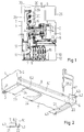
- a control panel for an air-insulated switchgear is equipped with a scaffold designed in particular for assembly, which serves at least as part of an outer control panel housing and preferably a trough-shaped rear wall (1) with right-angled edge strips (2 and 3), which is also profiled in a dimensionally stable manner
- Front frame (4) as well as a flat cover (5) at the top and a bottom plate (7) at the bottom at the bottom with C-shaped profile rails (8) integrally formed in the area of the side edges running into the scaffold depth.
- the front frame (4) has at least one, but in the present case two door openings (9, 10) arranged one above the other, which are closed with doors (11, 12) that can be lifted, swiveled and pivoted, and have access to a shift carriage (13 ) with circuit breaker (14) and drive (15) or to cable connections (16), voltage transformers (17) or current transformers (18).
- the circuit breaker (14) is electrically connected via bus contacts (19) on the one hand to busbars (20) and on the other hand to the current transformer (18) or the cable connections (16).
- the base plate (7) with the integrally molded profile rails (8) which essentially determines the base area of the switch panel, forms, like the large-area cover (5) produced with the same technology, with the integrally molded profile rails (6), due to the multiple angles, a torsionally rigid and lanyard secured against parallel displacement.
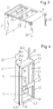
- the lower, cross-sectionally C-shaped profile rails (8) have a continuous, vertical backrest (8.1), the ends of which are on the one hand with vertical edge strips (2), with the rear wall (1) and with vertical side walls (4.1) of the Front frame (4) preferably through Rivets, rigidly connected.
- the front frame (4) has a one-piece front plate (4.2), from which the door openings (9, 10) are cut out and which have edge strips (4.3) that are angled all around in the housing depth on their outer circumference.
- the front frame is therefore also trough-shaped with high mechanical stability.
- the side walls (4.1) and (4.3) can be formed in one piece if the sheet metal plate ready for processing is of sufficient size. If the width of the sheet metal plate is insufficient, the side walls (4.1) are produced independently, as shown here, and are firmly connected, for example by riveting, to both the vertical edge strips (4.3) and the horizontal edge strips (4.3).
- the bottom plate (7) sits on the lower edge strip (3) of the rear wall (1) as on the lower edge strip (4.3) of the front frame (4). is riveted.
- the side edges (21) of the base plate (7) connecting the C profile rails (8) are angled downwards towards the edge strips (3 or 4.3) and stand on them.
- These side edges (21) have a width which is predetermined by the C-leg (22), on the edge of which the base plate (7) connects.
- the main surface of the base plate (7) is thus at a distance above the plane formed by the edge strips (3, 4.3). This distance is determined by the width of the side edges (21). Since these edges are as high as the C-leg (22) of the adjacent C-profile, the lower offset of the C-profile rail also rests on the edge strips (3 and 4.3) in a dimensionally stable manner.
- the base plate (7) is provided with at least one cutout (23) in which at least the cutout edges (24) running parallel to the front plate (4.2) or to the rear wall (2) are downward are angled to ensure sufficient rigidity of the base plate (7) and abrasion protection.
- the front plate (4.2) of the front frame (4) extends over a height which is determined by the door openings (9, 10).
- the front frame is provided with bars (26) on its side panels (4.1), which protrude into the depth of the housing, which protrude above the top edge strip (4.3) and there are rigidly connected to the associated end region of the cover (5) or the profile rails (6).
- the cover (5) is, for example, riveted to the vertical edge strips (2) of the rear wall (1) and, if appropriate, to an upper, horizontal, also angled edge strip.
- the spars (26) have a U-shaped, stable cross section and are arranged so that their open sides face each other.
- the control box (25) can be attached to the front legs (26.1) of the bars (26) which are parallel to the front plate (4.2). These legs end near and above the top edge strip (4.3).
- the leg (26.2) at the rear in the housing depth extends as a double bend on the respective side cheek (4.1) in the direction of the associated lower profile rail (8) and can collide with it and, if necessary, be mechanically firmly connected to further increase the rigidity.
- the cover (5) formed from a plate with its associated molded profile rails (6) extends from the rear wall (2) to the front frame (4) or to its spars (26) and is in each case firmly connected thereto, for example by rivets.
- ventilation openings (27) which have edge edges (28) which are angled downwards into the interior of the housing.
- supporting elements (29) extending into the interior of the housing are fixed, which are designed in particular as partitions and can be carriers of the busbars (20) or other components or separate functional spaces from one another which can result in overpressure as a result of arcing faults or the like.
- the individual ventilation openings (27) are therefore assigned to the outward opening pressure relief flaps (30), which automatically open when there is overpressure in the room in question, for example in the room receiving the circuit breaker (14), in the busbar area or in the room receiving the cable connections (16) and hot gas flows upwards into one Let the area flow out where the operating personnel are usually not.
- collars (31) are formed in one piece on the front plate (4.2), perpendicular to the plane of the plate, which delimit the respective opening edge and which have collar edge sections (32, 33) angled parallel to the plane of the front plate (4.2).
- the collar edge sections (33) provided on the vertical collar sections (31) have a crenellated or meandering shape and are directed away from the respective door opening (9 or 10).
- the horizontal collar edge sections (32) are designed as strips and are each angled upwards.
- a door provided with opposite collar sections can be raised and lowered about a vertical axis in such a way that the door can be brought into and out of engagement with the collar edge sections (33 and 32) by shifting the height. If the collar edge sections (32, 33) overlap in one of the door height positions, then an unintentional opening of the door is excluded even with high excess pressure in the device housing.
- the collar and the collar edge sections contribute to the additional stiffening of the front plate (4.2).
Landscapes
- Engineering & Computer Science (AREA)
- Power Engineering (AREA)
- Patch Boards (AREA)
- Switch Cases, Indication, And Locking (AREA)
- Distribution Board (AREA)
Applications Claiming Priority (2)
| Application Number | Priority Date | Filing Date | Title |
|---|---|---|---|
| DE19615313 | 1996-04-18 | ||
| DE1996115313 DE19615313A1 (de) | 1996-04-18 | 1996-04-18 | Schaltfeld |
Publications (2)
| Publication Number | Publication Date |
|---|---|
| EP0802597A2 true EP0802597A2 (fr) | 1997-10-22 |
| EP0802597A3 EP0802597A3 (fr) | 1998-12-16 |
Family
ID=7791635
Family Applications (1)
| Application Number | Title | Priority Date | Filing Date |
|---|---|---|---|
| EP97106220A Withdrawn EP0802597A3 (fr) | 1996-04-18 | 1997-04-16 | Tableau de distribution |
Country Status (2)
| Country | Link |
|---|---|
| EP (1) | EP0802597A3 (fr) |
| DE (1) | DE19615313A1 (fr) |
Cited By (2)
| Publication number | Priority date | Publication date | Assignee | Title |
|---|---|---|---|---|
| CN103701060A (zh) * | 2013-12-31 | 2014-04-02 | 昆山振宏电子机械有限公司 | 铠装移开式交流金属封闭开关柜 |
| EP4636963A1 (fr) * | 2024-04-16 | 2025-10-22 | Abb Schweiz Ag | Appareillage de commutation |
Families Citing this family (2)
| Publication number | Priority date | Publication date | Assignee | Title |
|---|---|---|---|---|
| DE10147342C2 (de) * | 2001-09-26 | 2003-09-25 | Eldon N V | Schaltschrank |
| DE102007014786B4 (de) * | 2007-03-28 | 2009-06-10 | Rittal Gmbh & Co. Kg | Bodenblechanordnung für einen Schaltschrank |
Family Cites Families (11)
| Publication number | Priority date | Publication date | Assignee | Title |
|---|---|---|---|---|
| DE7331465U (de) * | 1973-08-30 | 1973-12-20 | Rst Gmbh | Schaltschrank |
| DE7902216U1 (de) * | 1979-01-27 | 1979-06-21 | Peltzer Werke Kg, 5190 Stolberg | Geräteschrank |
| DE3300066A1 (de) * | 1983-01-04 | 1984-07-05 | Wilhelm 7913 Senden Bader | Schaltschrank |
| DE8300044U1 (de) * | 1983-01-04 | 1983-06-30 | Bader, Wilhelm, 7913 Senden | Blechschrank, insbesondere Schaltschrankgehäuse |
| DE3438603A1 (de) * | 1984-10-20 | 1985-06-27 | Ritter Starkstromtechnik GmbH & Co, 4600 Dortmund | Schaltschrank |
| DE3731547C3 (de) * | 1987-09-19 | 1995-05-04 | Loh Kg Rittal Werk | Schaltschrank |
| DE3812507A1 (de) * | 1988-04-15 | 1989-10-26 | Sachsenwerk Ag | Schaltfeld fuer eine gekapselte mittelspannungs-schaltanlage |
| DE3927835A1 (de) * | 1989-08-23 | 1991-02-28 | Ritter Starkstromtech | Gekapselte mittelspannungsschaltanlage |
| DE9305387U1 (de) * | 1993-04-08 | 1993-06-09 | Siemens AG, 8000 München | Schaltschrank |
| DE9305847U1 (de) * | 1993-04-20 | 1993-06-17 | Starkstrom-Anlagen Kautz GmbH, 5500 Trier | Schaltschrankrahmen für einen Schaltschrank |
| DE4441622A1 (de) * | 1994-11-23 | 1996-05-30 | Philips Patentverwaltung | Gestellschrank |
-
1996
- 1996-04-18 DE DE1996115313 patent/DE19615313A1/de not_active Withdrawn
-
1997
- 1997-04-16 EP EP97106220A patent/EP0802597A3/fr not_active Withdrawn
Cited By (2)
| Publication number | Priority date | Publication date | Assignee | Title |
|---|---|---|---|---|
| CN103701060A (zh) * | 2013-12-31 | 2014-04-02 | 昆山振宏电子机械有限公司 | 铠装移开式交流金属封闭开关柜 |
| EP4636963A1 (fr) * | 2024-04-16 | 2025-10-22 | Abb Schweiz Ag | Appareillage de commutation |
Also Published As
| Publication number | Publication date |
|---|---|
| DE19615313A1 (de) | 1997-10-23 |
| EP0802597A3 (fr) | 1998-12-16 |
Similar Documents
| Publication | Publication Date | Title |
|---|---|---|
| EP3103171A1 (fr) | Module de fond pour le châssis d'une armoire électrique | |
| EP0872000B1 (fr) | Jeu de barres omnibus pour installation de commutation basse tension | |
| DE69402525T2 (de) | Gerüst mit variabler grösse für elektrische und/oder elektronische anlage | |
| DE3300065A1 (de) | Schaltschrank | |
| EP3965240A1 (fr) | Dispositif de fixation et de câblage des unités électriques dans une armoire de distribution | |
| EP0442591A2 (fr) | Installation de commutation multichamp avec une disposition de barres omnibus | |
| EP0587820B1 (fr) | Installation de distribution basse tension visant a fournir ou a distribuer de l'energie electrique | |
| DE19816589C1 (de) | Mehrfeldrige Schaltanlage mit einer Sammelschienenanordnung | |
| DE19615313A1 (de) | Schaltfeld | |
| DE19811711C1 (de) | Wandbefestigtes Installationsgehäuse | |
| WO2019001610A1 (fr) | Agencement composé d'un socle d'armoire électrique sur lequel est monté un bâti d'armoire électrique, ainsi que rangée d'armoires électriques correspondante | |
| DE3300066A1 (de) | Schaltschrank | |
| DE19610347C1 (de) | Kabelkanalsystem für Büroeinrichtungen, insbesondere für EDV-Arbeitsplätze o. dgl. | |
| DE1591623B1 (de) | Schrank fuer Geraete der Nachrichtentechnik | |
| DE3243079A1 (de) | Schaltschrank | |
| EP0337270A1 (fr) | Unité fonctionnelle pour une installation de commutation blindée à moyenne tension | |
| WO1994024749A1 (fr) | Boites de sortie ou de raccordement pour barres omnibus dans des distributeurs a barres omnibus | |
| DE2515164A1 (de) | Elektrische schaltanlage fuer niederspannung | |
| DE19816623C2 (de) | Spritzwandmodul und aus Spritzwandmodulen aufgebaute Spritzwand | |
| DE4131800A1 (de) | Verpackungsmaschine | |
| DE29704305U1 (de) | Geräteschrank | |
| CH666376A5 (en) | Drawer inset for modular control appts. - has vertical cable shaft defined by aligned cut=outs in base of each insert | |
| EP1439061B1 (fr) | Pupitre de commande | |
| DE9312589U1 (de) | Niederspannungs-Schaltanlage mit einem in einem Gerüst abgestützten Träger für Schalt- und/oder Steuergeräte | |
| DE19737425A1 (de) | Schaltschrank mit einem Schwenkrahmen |
Legal Events
| Date | Code | Title | Description |
|---|---|---|---|
| PUAI | Public reference made under article 153(3) epc to a published international application that has entered the european phase |
Free format text: ORIGINAL CODE: 0009012 |
|
| AK | Designated contracting states |
Kind code of ref document: A2 Designated state(s): DE ES FR GB IT NL |
|
| 17P | Request for examination filed |
Effective date: 19971118 |
|
| PUAL | Search report despatched |
Free format text: ORIGINAL CODE: 0009013 |
|
| AK | Designated contracting states |
Kind code of ref document: A3 Designated state(s): DE ES FR GB IT NL |
|
| RAP1 | Party data changed (applicant data changed or rights of an application transferred) |
Owner name: ALSTOM SACHSENWERK GMBH |
|
| RAP1 | Party data changed (applicant data changed or rights of an application transferred) |
Owner name: AREVA SACHSENWERK GMBH |
|
| STAA | Information on the status of an ep patent application or granted ep patent |
Free format text: STATUS: THE APPLICATION IS DEEMED TO BE WITHDRAWN |
|
| 18D | Application deemed to be withdrawn |
Effective date: 20131101 |