EP0802551A2 - Dispositif de verrouillage pour cartouches à fusibles dans un sectionneur - Google Patents
Dispositif de verrouillage pour cartouches à fusibles dans un sectionneur Download PDFInfo
- Publication number
- EP0802551A2 EP0802551A2 EP97102389A EP97102389A EP0802551A2 EP 0802551 A2 EP0802551 A2 EP 0802551A2 EP 97102389 A EP97102389 A EP 97102389A EP 97102389 A EP97102389 A EP 97102389A EP 0802551 A2 EP0802551 A2 EP 0802551A2
- Authority
- EP
- European Patent Office
- Prior art keywords
- slide
- cover
- fuse
- longitudinal direction
- bolt
- Prior art date
- Legal status (The legal status is an assumption and is not a legal conclusion. Google has not performed a legal analysis and makes no representation as to the accuracy of the status listed.)
- Granted
Links
Images


Classifications
-
- H—ELECTRICITY
- H01—ELECTRIC ELEMENTS
- H01H—ELECTRIC SWITCHES; RELAYS; SELECTORS; EMERGENCY PROTECTIVE DEVICES
- H01H85/00—Protective devices in which the current flows through a part of fusible material and this current is interrupted by displacement of the fusible material when this current becomes excessive
- H01H85/02—Details
- H01H85/0208—Tools for inserting and removing fuses
-
- H—ELECTRICITY
- H01—ELECTRIC ELEMENTS
- H01H—ELECTRIC SWITCHES; RELAYS; SELECTORS; EMERGENCY PROTECTIVE DEVICES
- H01H31/00—Air-break switches for high tension without arc-extinguishing or arc-preventing means
- H01H31/02—Details
- H01H31/12—Adaptation for built-in fuse
- H01H31/122—Fuses mounted on, or constituting the movable contact parts of, the switch
Definitions
- the invention relates to a device for releasably locking fuse links in a NH fuse switch disconnector with switch frame and movable cover with respect to this, in which the fuse links are arranged next to one another transversely to their longitudinal direction, separated from one another by at least one phase partition and held by hanging parts by means of handle straps and at which can be brought into locking engagement with the respective grip tab in each case by a spring-loaded bolt.
- a latch made of plastic is resiliently arranged in the longitudinal direction of the fuse link outside the first handle tab so that the handle tab presses the bar in the longitudinal direction of the securing agent salt by manual force when it is inserted, so that the user then pushes the rear handle tab into the Press down and insert suspension parts.
- the spring behind the bolt pushes the fuse link back so far over the handle tab that the rear handle tab also engages in the recesses there and the fuse link is firmly locked.
- This known solution is a positive and non-positive locking, which can be released again by applying such a force by hand that the front tab can push the bolt back.
- the object of the invention is therefore to provide a device of the type mentioned in the introduction, in which the removal of the fuse links can be simplified and carried out at any time without touching personnel.
- this object is achieved in that at least two bolts are attached to a common slide, which is arranged transversely to the longitudinal direction of the fuse links arranged in the disconnector against the biasing force of a spring is displaceable and thereby brings the latches from the grip tabs out of locking engagement and which extends through a side wall of the cover to form a button.
- the removal of the fuse links before or after operation, ie after the energy has been switched off, is considerably simplified in the case of a device with the measures mentioned above.
- the operator only needs to press the button protruding from one side wall and can thus simultaneously unlock at least two securing inserts in such a way that both inserts fall out almost simultaneously when the cover tilts over or is held at an angle.
- the button is no less than a hand's width from the opposite side wall, as is the case with smaller disconnectors, for example size 00, then the user can unlock with one hand.
- the thumb grips one side wall and one of the fingers touches the key that protrudes opposite.
- the button is pressed in the above-mentioned transverse direction, ie transverse to the longitudinal direction of the fuse links. Their longitudinal direction is assumed in the direction of the two opposite contact blades or the connecting line between them.
- the slider thus extends at least over one, preferably over two or three fuse inserts arranged next to one another in this transverse direction, because the fuse inserts sit transversely next to one another such that their longitudinal directions are each parallel.
- the cover is pivotable relative to the switch frame.
- the possibility of making the cover removable from the switch frame is also particularly advantageous. Obviously, the fuse inserts can be unlocked and removed easily and without any problems and risk of injury.
- the button extending through the side wall of the cover in the said transverse direction protrudes half a finger width laterally out of the side wall. This makes the button easily accessible for every user. But it can also be useful to place a small trough in the side wall at the point of passage of the button, so that the button is accessible and operated by the user in the same way, but the outer contour of the entire lid is not exceeded becomes. As a result, the switch disconnectors can be arranged close together in compact assemblies, so that they take up little space.
- the bolt is designed as a hook connected to the slide via a web, which engages around the grip tab.
- This structure advantageously enables the arrangement of the plate-shaped or essentially flat grip tab between the slide on the one hand and the hook or bolt on the other.
- the latching or locking surface of the hook encompasses the grip tab in this way. This creates good opportunities to make optimal use of the space available in the disconnector. For example, one can avoid the unwanted pushing up of the grip tab in the longitudinal direction of the fuse link by the hook which grips the grip tab from above, while at the bottom, i.e. with respect to the handle tab on the side opposite the hook of the slide is arranged. This requires a minimum space for its extension in the transverse direction mentioned, also in the height that can be seen in the longitudinal direction of the fuse links.
- the front wall of the cover is closed by a window or even by a sliding window in which test holes for the voltage test are arranged. By sliding this window, the hole in question can either be covered or exposed. A voltage measuring tool is inserted through this hole up to the grip tab or contact knife. A minimum space is required for this correct application of the tool on the securing part.
- switch disconnectors in which this space is limited in relation to the position of the handle tab. For such an embodiment, the design of the bolt as a hook is very cheap because the relatively large slide is then to be arranged on the lower side of the handle tab and the hook with its locking or blocking surface on the top of the handle tab.
- the slide has an elongated box profile and receives a compression spring at the end opposite the button.
- the slide can be molded from solid, electrically insulating and durable plastic, for example, or injection molded.
- a favorable design for an elongated slide which preferably extends over two or three securing inserts arranged next to one another in the transverse direction mentioned is the box profile mentioned. Its cross-section is U-shaped, with the central web connecting the two free legs of the U being arranged forward toward the front wall of the cover. The hollow box of this slide profile is then behind this web.
- the compression spring mentioned can be received and locked in the cavity of this slide. It is supported against that side wall of the lid or an interposed web in the lid, which is opposite the side wall with the recessed grip through which the button protrudes.
- the slide can also be slidably arranged between a guide bracket attached to the cover and a preferably removable cover front wall.
- This configuration significantly improves the installation of the slide with or without its hook. Even if the slider is elongated and extends over all three fuse links arranged next to one another, it can be moved from, i.e. can be easily inserted from the front of the lid without unscrewing other parts on the lid beforehand.
- a part of the front wall of the lid is designed as a window or even as a sliding window. You can snap this out with the correct construction for the assembly of the slide, then insert the slide in the form of the elongated box profile with pre-tensioning against the compression spring and then snap the window back in.
- the guide angle mentioned which is to be thought of as L-shaped in cross section in one embodiment, can have legs so long that the leg heights correspond to the cross-sectional dimensions of the slide.
- the grip tab can then close the L-shaped guide bracket upwards like the second free leg of a U.
- the slidably reciprocating slide is then enclosed between the handle tab and the guide bracket as in a cage.
- either the front wall of the lid or its sliding window can close off the guide bracket to form a closed box housing. Tilting and jamming of the slider before and while the button is pressed is then excluded.
- the hole can be covered by the slide. After pushing up this window, the hole then moves vertically away from the covering walls (e.g. the slide) in the longitudinal direction of the fuse link and frees up the space behind for the grip tab for voltage measurement.
- the slide and the latches can be moved in one plane in front of the suspension parts leaving an insertion slot and behind the front wall of the cover.
- the elongated slide can be thought of as being placed in a vertical plane that is parallel to the front wall of the lid. The normal line of sight is then perpendicular to this plane. In the case of a flat front wall of the lid, in the preferred embodiment considered here, it is close to the viewing direction (1-5 mm) in front of it, or that The window or the sliding window is there.
- an inlet slope is formed on the side facing away from the locking surface of the bolt and / or between them.
- the plate to be locked in the embodiment under consideration here, namely the grip tab, can run against the inlet slope when pushed in and thus push it away against the spring pressure in the longitudinal direction of the slide so that the locking surface or locking surface when Inserting the grip tab into its end position is first pushed aside to snap back into locking engagement after the grip tab has been positioned.
- Different hook shapes are possible here.
- the entry slope should be on the side facing away from the locking surface of the bolt or next to it. You do not need a special tool to insert the tabs to be locked to bring the slide with its bolts into the unlocked position.
- Another advantageous embodiment of the invention is characterized in that blocking webs project from the slide approximately perpendicular to its longitudinal and sliding direction and at a distance from one another. Similar to the first embodiment with the hook-shaped bolt, which is also connected to the slide via a web, the bolts themselves are designed as such webs. The hook at the end is missing. This embodiment does not encompass the grip tabs to be locked but lies in front of them from one side, so that the grip tabs on this side cannot be removed or can fall out without deliberate unlocking.
- the number of blocking webs corresponds to the number of fuse links to be locked in the switch disconnector.
- the securing insert generally designated 1 in the embodiments shown here, is fastened via its grip tab 2 in the suspension parts 4 forming an insertion slot 3.
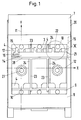
- FIGS. 1 and 2 which consists of switch frame 5 and cover 6 with handle 7, the suspension parts 4 are located in cover 6.
- Front cover 8 is closed at the front by a sliding window 9, in which test holes 10 are provided at the top and bottom are provided for the voltage test.
- the terms “above” and “below” are taken from the consideration of FIGS. 1 and 2.
- the dash-dotted lines 11 in FIG. 1 extend upwards or downwards, which represent the longitudinal direction of the fuse links 1 not shown in FIG. 1 but arranged in the disconnector. If an imaginary coordinate system is spanned, these straight lines, which illustrate the longitudinal direction 11, run in the Y direction. Right across, i.e.
- the slide 14 with the bolt 15 is displaceable against the X direction (horizontal line 12) against the action of a compression spring 16.
- three securing inserts 1 lie next to one another in the transverse direction 12, which is why three bars 15 are also formed on the slide 14.
- the latches 15 are connected in hook form on the slide 14 via the respective web 17.
- These hook-shaped latches 15 can be seen encompassing the handle tab 2.
- the slide 14 is located on one side of the handle tab 2 (below), and the latch 15 thus engages over the hook-like shape on the opposite side the grip tab 2 that the locking surface 18 shown in Figure 3 is above the grip tab 2 with the result that they can not move out of the insertion slot 3 between the suspension parts 4 upwards in the longitudinal direction 11 in the + Y direction.
- the switch frame 5 also has phase partitions 24 which extend between the fuse inserts 1, not shown, up to the position of the slide 14.
- the cover 6 can be pivoted up into the open position (not shown) with the aid of the bearing guide 26 by pulling the handle 7 in FIG. 1 to the left and in FIG. 2 to the left.
- the switch frame 5 is fastened via the mounting holes 27 for mounting on a base plate, for example on the plate of a cabinet.
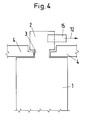
- the upper part of the cover front wall 8 is cut in a plane perpendicular to the paper plane in FIG. 1 and through the longitudinal direction 11.
- a connecting web 28 which is part of an L-shaped guide bracket 29, on the horizontally lying connecting web 28 the slide 14 is guided.
- the cover is also stiffened by this guide bracket 29.
- the space within this guide bracket 29 behind the sliding window 9 is just enough to accommodate the hollow, cross-sectionally U-shaped box profile of the slide 14 on the outside at the free end of the upper leg of the U, the bars 15 are formed vertically upright.
- the cross-sectional design of the slide 14 of the other embodiment shown in FIG. 5 has a similar structure.
- the user can push the slide 14 out of the position shown in FIG. 5 against the force of the compression spring 16 by applying pressure in the transverse direction 12.
Landscapes
- Fuses (AREA)
- Switch Cases, Indication, And Locking (AREA)
- Push-Button Switches (AREA)
- Keying Circuit Devices (AREA)
Applications Claiming Priority (2)
| Application Number | Priority Date | Filing Date | Title |
|---|---|---|---|
| DE19615444A DE19615444A1 (de) | 1996-04-19 | 1996-04-19 | Verriegelungseinrichtung für Sicherungseinsätze in einem Trennschalter |
| DE19615444 | 1996-04-19 |
Publications (3)
| Publication Number | Publication Date |
|---|---|
| EP0802551A2 true EP0802551A2 (fr) | 1997-10-22 |
| EP0802551A3 EP0802551A3 (fr) | 1998-01-28 |
| EP0802551B1 EP0802551B1 (fr) | 2001-12-05 |
Family
ID=7791710
Family Applications (1)
| Application Number | Title | Priority Date | Filing Date |
|---|---|---|---|
| EP97102389A Expired - Lifetime EP0802551B1 (fr) | 1996-04-19 | 1997-02-14 | Dispositif de verrouillage pour cartouches à fusibles dans un sectionneur |
Country Status (4)
| Country | Link |
|---|---|
| EP (1) | EP0802551B1 (fr) |
| AT (1) | ATE210335T1 (fr) |
| DE (2) | DE19615444A1 (fr) |
| PL (1) | PL182231B1 (fr) |
Cited By (2)
| Publication number | Priority date | Publication date | Assignee | Title |
|---|---|---|---|---|
| DE102006049812A1 (de) * | 2006-10-17 | 2008-04-24 | Siemens Ag | Sicherungslasttrennschalter und Verriegelungseinrichtung für einen Sicherungslasttrennschalter |
| EP2428972A3 (fr) * | 2010-09-10 | 2013-04-24 | Apator S.A. | Sectionneur électrique doté d'un blocage contre l'extraction du couvercle |
Families Citing this family (1)
| Publication number | Priority date | Publication date | Assignee | Title |
|---|---|---|---|---|
| DE19849875C1 (de) * | 1998-10-29 | 2000-02-17 | Geyer Ag | Verriegelungseinrichtung für einen zwei- oder vierpoligen, aus einzeln betätigbaren Polen zusammengesetzten NH-Sicherungstrenner oder NH-Sicherungslasttrenner |
Family Cites Families (9)
| Publication number | Priority date | Publication date | Assignee | Title |
|---|---|---|---|---|
| DE1106836B (de) * | 1956-03-15 | 1961-05-18 | Pfisterer Elektrotech Karl | Mehrpoliger Sicherungstrennschalter mit von aussen einzeln loesbaren Sicherungen |
| DE2254847B2 (de) * | 1972-11-09 | 1978-11-30 | Licentia Patent-Verwaltungs-Gmbh, 6000 Frankfurt | Einfahr-Anordnung |
| DE7417818U (de) * | 1974-05-22 | 1974-09-19 | Siemens Ag | Griffeinsatz zur Aufnahme von mehreren, auswechselbaren Schmelzsicherungseinsätzen |
| DE7503203U (de) * | 1975-02-04 | 1975-06-05 | Driescher F Spezialfabrik Fuer Elek | Haltevorrichtung tür Sicherungseinsätze |
| DE2551422C3 (de) * | 1975-11-15 | 1979-05-03 | Christian Geyer Gmbh & Co, 8500 Nuernberg | Niederspannungs-Hochleistungs-Lastschaltsicherung |
| CH619320A5 (en) * | 1977-10-03 | 1980-09-15 | Weber Ag Fab Elektro | Operating handle for a low-voltage, high-rupture-capacity (NH) fuse |
| NL9100415A (nl) * | 1991-03-07 | 1992-10-01 | Tech Handelsmaatschappij Distr | Samenstel van een elektrische schakelaar en een zekeringhouder. |
| DE9305969U1 (de) * | 1993-04-20 | 1993-07-01 | Christian Geyer GmbH & Co, 8500 Nürnberg | NH-Sicherung |
| DE9403039U1 (de) * | 1994-02-24 | 1994-07-28 | Peterreins Schalttechnik GmbH, 91126 Schwabach | Mit Sicherungen versehene Schaltanordnung |
-
1996
- 1996-04-19 DE DE19615444A patent/DE19615444A1/de not_active Withdrawn
-
1997
- 1997-02-14 EP EP97102389A patent/EP0802551B1/fr not_active Expired - Lifetime
- 1997-02-14 AT AT97102389T patent/ATE210335T1/de active
- 1997-02-14 DE DE59705613T patent/DE59705613D1/de not_active Expired - Lifetime
- 1997-04-17 PL PL97319530A patent/PL182231B1/pl unknown
Cited By (2)
| Publication number | Priority date | Publication date | Assignee | Title |
|---|---|---|---|---|
| DE102006049812A1 (de) * | 2006-10-17 | 2008-04-24 | Siemens Ag | Sicherungslasttrennschalter und Verriegelungseinrichtung für einen Sicherungslasttrennschalter |
| EP2428972A3 (fr) * | 2010-09-10 | 2013-04-24 | Apator S.A. | Sectionneur électrique doté d'un blocage contre l'extraction du couvercle |
Also Published As
| Publication number | Publication date |
|---|---|
| ATE210335T1 (de) | 2001-12-15 |
| PL182231B1 (pl) | 2001-11-30 |
| PL319530A1 (en) | 1997-10-27 |
| EP0802551A3 (fr) | 1998-01-28 |
| DE19615444A1 (de) | 1997-10-23 |
| EP0802551B1 (fr) | 2001-12-05 |
| DE59705613D1 (de) | 2002-01-17 |
Similar Documents
| Publication | Publication Date | Title |
|---|---|---|
| EP1993116B1 (fr) | Dispositif de commutation de puissance à fusibles | |
| WO2017182033A1 (fr) | Agencement permettant la connexion sans risque de contact d'un système de rails collecteurs de courant | |
| DE102007055047B4 (de) | Schließvorrichtung für einen Einschubrahmen, Einschubrahmen,Betätigungselement und Verriegelungselement | |
| DE2754656C2 (de) | Elektrischer Steckverbinder | |
| DE4210953A1 (de) | Lastschaltleiste | |
| EP0056558B1 (fr) | Plaque à fiches pour un interrupteur de sécurité à basse tension | |
| AT394284B (de) | Sicherheitslastschaltleiste (einbauleiste) | |
| DE4207156C2 (de) | Konstruktion eines elektrischen Schalters und eines Sicherungshalters | |
| DE69523579T2 (de) | Gehäuse für ein elektrisches Gerät | |
| EP0802551B1 (fr) | Dispositif de verrouillage pour cartouches à fusibles dans un sectionneur | |
| EP1246213B1 (fr) | Dispositif de commutation de puissance, de dimension 00 | |
| AT501539A1 (de) | Bauteil zum raschen verbinden von enden | |
| DE2819812A1 (de) | Zubehoer fuer gehaeuseprofile | |
| DE3922882C2 (de) | Verriegelbare Steckverbindung | |
| DE10054168A1 (de) | Sicherungleiste | |
| DE3314681C2 (fr) | ||
| DE3931660C1 (en) | Low voltage high power fused switch isolator - has electrically insulating over-reaching protection in isolator cover | |
| DE29605800U1 (de) | Lastschaltleiste mit einem Gehäuse und mit einem Deckel | |
| CH653181A5 (en) | Electrical connecting element | |
| DE3510390A1 (de) | Sicherheitsvorrichtung, insbesondere fuer anschluesse an schienenverteiler-systemen | |
| DE4111157A1 (de) | Nh-sicherungslasttrenner in leistenbauform | |
| DE8716402U1 (de) | Staubsauger mit einer einteiligen Drucktaste | |
| AT335546B (de) | Stromverteilungssystem | |
| DE29714134U1 (de) | Verriegelungsschieber für Sicherung | |
| DE10054170C2 (de) | Sicherungsleiste |
Legal Events
| Date | Code | Title | Description |
|---|---|---|---|
| PUAI | Public reference made under article 153(3) epc to a published international application that has entered the european phase |
Free format text: ORIGINAL CODE: 0009012 |
|
| AK | Designated contracting states |
Kind code of ref document: A2 Designated state(s): AT BE CH DE LI |
|
| AX | Request for extension of the european patent |
Free format text: SI PAYMENT 970225 |
|
| PUAL | Search report despatched |
Free format text: ORIGINAL CODE: 0009013 |
|
| AK | Designated contracting states |
Kind code of ref document: A3 Designated state(s): AT BE CH DE LI |
|
| AX | Request for extension of the european patent |
Free format text: SI PAYMENT 970225 |
|
| 17P | Request for examination filed |
Effective date: 19980218 |
|
| 17Q | First examination report despatched |
Effective date: 20000201 |
|
| GRAG | Despatch of communication of intention to grant |
Free format text: ORIGINAL CODE: EPIDOS AGRA |
|
| GRAG | Despatch of communication of intention to grant |
Free format text: ORIGINAL CODE: EPIDOS AGRA |
|
| GRAH | Despatch of communication of intention to grant a patent |
Free format text: ORIGINAL CODE: EPIDOS IGRA |
|
| GRAH | Despatch of communication of intention to grant a patent |
Free format text: ORIGINAL CODE: EPIDOS IGRA |
|
| GRAA | (expected) grant |
Free format text: ORIGINAL CODE: 0009210 |
|
| AK | Designated contracting states |
Kind code of ref document: B1 Designated state(s): AT BE CH DE LI |
|
| AX | Request for extension of the european patent |
Free format text: SI PAYMENT 19970225 |
|
| PG25 | Lapsed in a contracting state [announced via postgrant information from national office to epo] |
Ref country code: BE Free format text: LAPSE BECAUSE OF FAILURE TO SUBMIT A TRANSLATION OF THE DESCRIPTION OR TO PAY THE FEE WITHIN THE PRESCRIBED TIME-LIMIT Effective date: 20011205 |
|
| REF | Corresponds to: |
Ref document number: 210335 Country of ref document: AT Date of ref document: 20011215 Kind code of ref document: T |
|
| REG | Reference to a national code |
Ref country code: CH Ref legal event code: EP |
|
| RAP2 | Party data changed (patent owner data changed or rights of a patent transferred) |
Owner name: EFEN GMBH |
|
| REF | Corresponds to: |
Ref document number: 59705613 Country of ref document: DE Date of ref document: 20020117 |
|
| REG | Reference to a national code |
Ref country code: CH Ref legal event code: NV Representative=s name: ISLER & PEDRAZZINI AG |
|
| PLBE | No opposition filed within time limit |
Free format text: ORIGINAL CODE: 0009261 |
|
| STAA | Information on the status of an ep patent application or granted ep patent |
Free format text: STATUS: NO OPPOSITION FILED WITHIN TIME LIMIT |
|
| 26N | No opposition filed | ||
| PGFP | Annual fee paid to national office [announced via postgrant information from national office to epo] |
Ref country code: CH Payment date: 20070214 Year of fee payment: 11 |
|
| REG | Reference to a national code |
Ref country code: CH Ref legal event code: PCAR Free format text: ISLER & PEDRAZZINI AG;POSTFACH 1772;8027 ZUERICH (CH) |
|
| REG | Reference to a national code |
Ref country code: CH Ref legal event code: PL |
|
| PG25 | Lapsed in a contracting state [announced via postgrant information from national office to epo] |
Ref country code: LI Free format text: LAPSE BECAUSE OF NON-PAYMENT OF DUE FEES Effective date: 20080229 Ref country code: CH Free format text: LAPSE BECAUSE OF NON-PAYMENT OF DUE FEES Effective date: 20080229 |
|
| PGFP | Annual fee paid to national office [announced via postgrant information from national office to epo] |
Ref country code: AT Payment date: 20160218 Year of fee payment: 20 |
|
| PGFP | Annual fee paid to national office [announced via postgrant information from national office to epo] |
Ref country code: DE Payment date: 20160429 Year of fee payment: 20 |
|
| REG | Reference to a national code |
Ref country code: DE Ref legal event code: R071 Ref document number: 59705613 Country of ref document: DE |
|
| REG | Reference to a national code |
Ref country code: AT Ref legal event code: MK07 Ref document number: 210335 Country of ref document: AT Kind code of ref document: T Effective date: 20170214 |