EP0802376B1 - Elément pour échangeur de chaleur en profilé extrudé en aluminium - Google Patents
Elément pour échangeur de chaleur en profilé extrudé en aluminium Download PDFInfo
- Publication number
- EP0802376B1 EP0802376B1 EP97105332A EP97105332A EP0802376B1 EP 0802376 B1 EP0802376 B1 EP 0802376B1 EP 97105332 A EP97105332 A EP 97105332A EP 97105332 A EP97105332 A EP 97105332A EP 0802376 B1 EP0802376 B1 EP 0802376B1
- Authority
- EP
- European Patent Office
- Prior art keywords
- heat exchanger
- profile
- exchanger element
- element according
- pipeline
- Prior art date
- Legal status (The legal status is an assumption and is not a legal conclusion. Google has not performed a legal analysis and makes no representation as to the accuracy of the status listed.)
- Expired - Lifetime
Links
- XAGFODPZIPBFFR-UHFFFAOYSA-N aluminium Chemical compound [Al] XAGFODPZIPBFFR-UHFFFAOYSA-N 0.000 title claims abstract description 16
- 229910052782 aluminium Inorganic materials 0.000 title claims abstract description 16
- 239000004411 aluminium Substances 0.000 title claims abstract 3
- 230000005855 radiation Effects 0.000 claims abstract description 16
- 238000001125 extrusion Methods 0.000 claims description 4
- 238000001816 cooling Methods 0.000 description 4
- 238000005452 bending Methods 0.000 description 2
- 238000009434 installation Methods 0.000 description 2
- 230000015572 biosynthetic process Effects 0.000 description 1
- 230000001419 dependent effect Effects 0.000 description 1
- 238000004519 manufacturing process Methods 0.000 description 1
- 230000003287 optical effect Effects 0.000 description 1
- 238000007665 sagging Methods 0.000 description 1
- 125000006850 spacer group Chemical group 0.000 description 1
- 230000007704 transition Effects 0.000 description 1
Images
Classifications
-
- F—MECHANICAL ENGINEERING; LIGHTING; HEATING; WEAPONS; BLASTING
- F24—HEATING; RANGES; VENTILATING
- F24F—AIR-CONDITIONING; AIR-HUMIDIFICATION; VENTILATION; USE OF AIR CURRENTS FOR SCREENING
- F24F5/00—Air-conditioning systems or apparatus not covered by F24F1/00 or F24F3/00, e.g. using solar heat or combined with household units such as an oven or water heater
- F24F5/0089—Systems using radiation from walls or panels
-
- F—MECHANICAL ENGINEERING; LIGHTING; HEATING; WEAPONS; BLASTING
- F24—HEATING; RANGES; VENTILATING
- F24D—DOMESTIC- OR SPACE-HEATING SYSTEMS, e.g. CENTRAL HEATING SYSTEMS; DOMESTIC HOT-WATER SUPPLY SYSTEMS; ELEMENTS OR COMPONENTS THEREFOR
- F24D3/00—Hot-water central heating systems
- F24D3/12—Tube and panel arrangements for ceiling, wall, or underfloor heating
- F24D3/16—Tube and panel arrangements for ceiling, wall, or underfloor heating mounted on, or adjacent to, a ceiling, wall or floor
- F24D3/165—Suspended radiant heating ceiling
-
- F—MECHANICAL ENGINEERING; LIGHTING; HEATING; WEAPONS; BLASTING
- F24—HEATING; RANGES; VENTILATING
- F24F—AIR-CONDITIONING; AIR-HUMIDIFICATION; VENTILATION; USE OF AIR CURRENTS FOR SCREENING
- F24F5/00—Air-conditioning systems or apparatus not covered by F24F1/00 or F24F3/00, e.g. using solar heat or combined with household units such as an oven or water heater
- F24F5/0089—Systems using radiation from walls or panels
- F24F5/0092—Systems using radiation from walls or panels ceilings, e.g. cool ceilings
-
- F—MECHANICAL ENGINEERING; LIGHTING; HEATING; WEAPONS; BLASTING
- F28—HEAT EXCHANGE IN GENERAL
- F28F—DETAILS OF HEAT-EXCHANGE AND HEAT-TRANSFER APPARATUS, OF GENERAL APPLICATION
- F28F1/00—Tubular elements; Assemblies of tubular elements
- F28F1/10—Tubular elements and assemblies thereof with means for increasing heat-transfer area, e.g. with fins, with projections, with recesses
- F28F1/12—Tubular elements and assemblies thereof with means for increasing heat-transfer area, e.g. with fins, with projections, with recesses the means being only outside the tubular element
- F28F1/14—Tubular elements and assemblies thereof with means for increasing heat-transfer area, e.g. with fins, with projections, with recesses the means being only outside the tubular element and extending longitudinally
- F28F1/16—Tubular elements and assemblies thereof with means for increasing heat-transfer area, e.g. with fins, with projections, with recesses the means being only outside the tubular element and extending longitudinally the means being integral with the element, e.g. formed by extrusion
-
- F—MECHANICAL ENGINEERING; LIGHTING; HEATING; WEAPONS; BLASTING
- F28—HEAT EXCHANGE IN GENERAL
- F28F—DETAILS OF HEAT-EXCHANGE AND HEAT-TRANSFER APPARATUS, OF GENERAL APPLICATION
- F28F1/00—Tubular elements; Assemblies of tubular elements
- F28F1/10—Tubular elements and assemblies thereof with means for increasing heat-transfer area, e.g. with fins, with projections, with recesses
- F28F1/12—Tubular elements and assemblies thereof with means for increasing heat-transfer area, e.g. with fins, with projections, with recesses the means being only outside the tubular element
- F28F1/14—Tubular elements and assemblies thereof with means for increasing heat-transfer area, e.g. with fins, with projections, with recesses the means being only outside the tubular element and extending longitudinally
- F28F1/20—Tubular elements and assemblies thereof with means for increasing heat-transfer area, e.g. with fins, with projections, with recesses the means being only outside the tubular element and extending longitudinally the means being attachable to the element
-
- F—MECHANICAL ENGINEERING; LIGHTING; HEATING; WEAPONS; BLASTING
- F28—HEAT EXCHANGE IN GENERAL
- F28F—DETAILS OF HEAT-EXCHANGE AND HEAT-TRANSFER APPARATUS, OF GENERAL APPLICATION
- F28F2255/00—Heat exchanger elements made of materials having special features or resulting from particular manufacturing processes
- F28F2255/16—Heat exchanger elements made of materials having special features or resulting from particular manufacturing processes extruded
-
- Y—GENERAL TAGGING OF NEW TECHNOLOGICAL DEVELOPMENTS; GENERAL TAGGING OF CROSS-SECTIONAL TECHNOLOGIES SPANNING OVER SEVERAL SECTIONS OF THE IPC; TECHNICAL SUBJECTS COVERED BY FORMER USPC CROSS-REFERENCE ART COLLECTIONS [XRACs] AND DIGESTS
- Y02—TECHNOLOGIES OR APPLICATIONS FOR MITIGATION OR ADAPTATION AGAINST CLIMATE CHANGE
- Y02B—CLIMATE CHANGE MITIGATION TECHNOLOGIES RELATED TO BUILDINGS, e.g. HOUSING, HOUSE APPLIANCES OR RELATED END-USER APPLICATIONS
- Y02B30/00—Energy efficient heating, ventilation or air conditioning [HVAC]
Definitions
- the invention relates to a heat exchanger element made of an extruded aluminum profile, wherein at least one can be acted upon with a heat exchange medium Pipeline can be integrated.
- the central axis of the pipeline extends in the longitudinal direction of the aluminum extrusion, which is at least one of the outer radius Has pipeline adapted, shell-shaped contact piece.
- Such heat exchanger elements are for example from DE-U-93 15 709.6 known as ceiling profiles for a chilled ceiling. This is said to ascend warm Indoor air to be cooled on the ceiling.
- the possible large-area cooling there allows relatively low airflow speeds and thus reduces the main disadvantages conventional air conditioners, which are usually neither completely silent yet can be operated entirely without a train.
- the known heat exchanger elements designed as ceiling profiles for a chilled ceiling are each provided with a web section on which a holding device is molded with which the heat exchanger element is attached to a cooling tube can be. From the longitudinal edges of the web section are leg sections angled. One of the two leg sections is thus in the form of an air guide leg Inclined in the direction of a heat exchanger element closest in the installation position, that between the ceiling profiles an air duct in the direction of the one above Heat exchanger element lying cooling tube is formed.
- a major disadvantage of the known heat exchanger elements is that their usability as chilled ceiling elements is limited because their relative large overall height requires large clear false ceiling spaces. The possible uses are therefore dependent on relatively large storey heights.
- the invention has for its object a heat exchanger element of the beginning type described so that it has the disadvantages mentioned above does not have and is also characterized in particular by great flexural rigidity, without the need for additional components that increase stability.
- the heat exchanger element according to the invention receives the by the arrangement of the Radiation area forming profile parts to each other a stem-shaped contour and draws as a result of its high bending stiffness, low overall height and a large heat transfer area with appropriate heat transfer capacity.
- the heat exchanger element can be an extruded aluminum profile in lengths up to Make 4 m. Such long heat exchanger elements reduce the manufacturing, assembly and installation effort compared to conventional heat exchanger elements considerably.
- the heat transfer surfaces of the heat exchanger element according to the invention are much larger than its projection area. Since the heat exchanger element with its coldest parts directly aligned with the lounge area of the room can be a large share of radiant heat exchange in the total output achieve. Finally, the good convective heat transfer conditions contribute of the heat exchanger element according to the invention high overall performance.
- the cup-shaped contact pieces limited at least one expansion joint.
- the expansion joint provided in the extruded aluminum profile between the shell-shaped Contact pieces make it possible to pretension them against the pipeline to press, for which purpose the pipeline is preferably widened slightly after the heat exchanger element has been pushed onto the pipeline.
- the heat exchanger element according to the invention are two with a radiation surface facing the room Profile parts arranged roof-shaped to each other and at their diverging lower Provide the ends with horizontally aligned longitudinal edge strips.
- a third Profile part are arranged, preferably with a horizontally aligned Longitudinal edge strips complete.
- heat exchanger element according to the invention is on the opposite side of the pipeline to the third profile part bowl-shaped contact piece molded hollow bar provided with the third Profile part is aligned.
- the hollow web encloses the expansion joint and enables one in its upper end screw channel running in the longitudinal direction of the profile.
- the frame legs Be like that trained heat exchanger elements between two opposite frame legs a frame arranged, the frame legs the front sides of the Cover profiles, so the profiles can be easily fixed in that screw bolts inserted through correspondingly placed holes in the frame legs be screwed into the screw channels of the profiles.
- a particularly advantageous embodiment of the heat exchanger element according to the invention provides that three profile parts each forming a radiation surface are ⁇ -shaped to one another are arranged.
- the ⁇ -shaped arrangement of the three radiation surfaces of the profile not only gives this great bending stiffness, but also increases the torsional stiffness of the profile extraordinary.
- the contact piece directly adjacent to the pipe with the adjoining ones Forms side pieces of the substantially horizontally oriented profile part the coldest areas that face the room directly. This allows one Achieve maximum share of radiant heat exchange in the total output.
- While that facing the lounge area of a room is essentially horizontal aligned profile part is in direct contact with the tube and consequently forms the coldest partial areas are according to a further embodiment of the invention the two roof-shaped profiles with each other with an intermediate piece each connected to a bowl-shaped contact piece.
- the bowl-shaped contact pieces can preferably run in an arc shape press against the pipeline under pre-tension and promote heat transfer from the pipeline to the heat exchanger element.
- the invention proposes that in at least one corner region of the profile Longitudinal direction of the profile screw channel is provided.
- Threaded bolts inserted through holes in the frame legs can be again screw into the screw channels and thereby prevent unintentional Rotation of the heat exchanger elements by the one defined by the pipeline Axis.
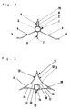
- the heat exchanger element according to FIG. 1 consists of an extruded aluminum profile 1, which is pushed coaxially onto a pipeline 2, with a heat exchange medium is applied.
- the aluminum extruded profile 1 has a bowl-shaped contact piece 3, the the outer radius of the pipe 2 is adapted.
- Two go from contact piece 3 roof-shaped mutually arranged profile parts 4, which at their diverging lower Merge ends into horizontally aligned longitudinal edge strips 5.
- profile parts 4 Between the profile parts 4 is a third profile part in the plane of the bisector 6 arranged that at its lower edge with a horizontally oriented longitudinal edge strip 7 completes.
- a hollow web 8 is formed, which includes an expansion joint 9. This enables an elastic expansion of the contact piece 3 due to an expansion of the pipeline 2, whereby the aluminum extrusion 1 exerted on the pipe 2 Contact pressure can be increased accordingly.
- the heat exchanger element shown in FIG. 2 consists of an extruded aluminum profile 11, which is also coaxial with a heat exchanger medium Pipe 2 is pushed on.
- the aluminum extruded profile 11 has three profile parts each forming a radiation surface 12, 12 and 13, which are arranged A-shaped to each other.
- the roof-shaped Profile parts 12, 12 have concave radiation surfaces, whereas this essentially horizontally aligned profile part 13 as the radiation surface of the pipeline immediately adjacent, externally convex contact piece 14 and laterally on it has subsequent concave side pieces 15.
- a contact piece 16 is formed on the inside of each profile part 12 via an intermediate piece 17.
- the inside concave contact piece 14 of the profile part 13 lies directly against the outside of the pipeline 2, so that when it is expanded Extruded aluminum profile 11 increasingly presses against the pipeline 2.
Landscapes
- Engineering & Computer Science (AREA)
- General Engineering & Computer Science (AREA)
- Mechanical Engineering (AREA)
- Physics & Mathematics (AREA)
- Chemical & Material Sciences (AREA)
- Combustion & Propulsion (AREA)
- Thermal Sciences (AREA)
- Sustainable Development (AREA)
- Life Sciences & Earth Sciences (AREA)
- Geometry (AREA)
- Heat-Exchange Devices With Radiators And Conduit Assemblies (AREA)
- Cooling Or The Like Of Semiconductors Or Solid State Devices (AREA)
- Extrusion Of Metal (AREA)
- Separation By Low-Temperature Treatments (AREA)
Claims (10)
- Elément pour échangeur de chaleur, constitué d'un profilé extrudé d'aluminium, auquel peut être intégré au moins un conduit qui peut être alimenté en le milieu de l'échangeur de chaleur et dont l'axe médian s'étend dans la direction longitudinale du profilé, qui comporte au moins une pièce de contact en forme de coquille adaptée au rayon extérieur du conduit, caractérisé par au moins une partie (4,6,8 et 12,13) de profilé issue, du côté éloigné du conduit (2), de chaque pièce (3,4,16) de contact et formant une surface rayonnante, le tracé des bords longitudinaux extérieurs des parties du profilé étant défini par les sommets d'un triangle.
- Elément pour échangeur de chaleur suivant la revendication 1, caractérisé en ce qu'il est délimité au moins un joint (9) de dilatation par des bandes marginales longitudinales opposées des pièces (3,14,16) de contact en forme de coquille.
- Elément pour échangeur de chaleur suivant la revendication 1 ou 2, caractérisé en ce que deux parties (4) de profilé munies chacune d'une surface rayonnante tournée vers l'espace sont disposées en forme de toit l'une par rapport à l'autre et sont munies à leurs extrémités inférieures divergentes de bandes (5) marginales longitudinales dirigées horizontalement.
- Elément pour échangeur de chaleur suivant la revendication 3, caractérisé en ce qu'il est prévu entre les parties (4) du profilé disposées en forme de toit l'une par rapport à l'autre, dans le plan de la bissectrice, une troisième partie (6) de profilé, qui se termine par une bande (7) marginale longitudinale dirigée horizontalement.
- Elément pour échangeur de chaleur suivant la revendication 4, caractérisé en ce qu'il est prévu du côté du conduit (2) qui fait face à la troisième partie (6) du profilé une barrette (8) creuse issue d'une pièce de contact en forme de coquille et alignée avec la troisième partie (6) du profilé.
- Elément pour échangeur de chaleur suivant la revendication 5, caractérisé en ce qu'il est prévu à l'extrémité supérieure de la barrette (8) creuse un canal (10) hélicoïdal s'étendant dans la direction longitudinale du profilé (1).
- Elément pour échangeur de chaleur suivant la revendication 1 ou 2, caractérisé en ce que trois parties (12,12,13) de profilé formant chacune une surface rayonnante sont disposées en forme de Δ les unes par rapport aux autres.
- Elément pour échangeur de chaleur suivant la revendication 7, caractérisé en ce que chaque surface rayonnante de deux parties (12,12) de profilé dirigées en forme de toit l'une par rapport à l'autre est réalisée de manière concave et la surface de radiation d'une partie (13) de profilé dirigée horizontalement est réalisée de manière convexe du côté extérieur sur une pièce (14) de contact directement voisine du conduit (2) et de manière concave du côté extérieur sur des pièces latérales qui s'y rattachent.
- Elément pour échangeur de chaleur suivant la revendication 8, caractérisé en ce que les deux parties (12) de profilé disposées en forme de toit l'une par rapport à l'autre sont reliées par chacune une pièce (17) intermédiaire à chacune une pièce (16) de contact en forme de coquille.
- Elément pour échangeur de chaleur suivant l'une des revendications 7 à 9, caractérisé en ce qu'il est prévu dans au moins une zone de sommet du profilé (11) un canal (18) hélicoïdal s'étendant dans la direction longitudinale du profilé.
Applications Claiming Priority (2)
| Application Number | Priority Date | Filing Date | Title |
|---|---|---|---|
| DE19615419A DE19615419C1 (de) | 1996-04-19 | 1996-04-19 | Wärmetauscherelement aus einem Aluminium-Strangpreßprofil |
| DE19615419 | 1996-04-19 |
Publications (3)
| Publication Number | Publication Date |
|---|---|
| EP0802376A2 EP0802376A2 (fr) | 1997-10-22 |
| EP0802376A3 EP0802376A3 (fr) | 1998-10-21 |
| EP0802376B1 true EP0802376B1 (fr) | 1999-06-23 |
Family
ID=7791694
Family Applications (1)
| Application Number | Title | Priority Date | Filing Date |
|---|---|---|---|
| EP97105332A Expired - Lifetime EP0802376B1 (fr) | 1996-04-19 | 1997-03-29 | Elément pour échangeur de chaleur en profilé extrudé en aluminium |
Country Status (4)
| Country | Link |
|---|---|
| EP (1) | EP0802376B1 (fr) |
| AT (1) | ATE181594T1 (fr) |
| DE (2) | DE19615419C1 (fr) |
| ES (1) | ES2134042T3 (fr) |
Families Citing this family (13)
| Publication number | Priority date | Publication date | Assignee | Title |
|---|---|---|---|---|
| EP1061309A1 (fr) * | 1999-06-16 | 2000-12-20 | Frans van Zaal B.V. | Procédé de fabrication d'un tube de chauffage ou de réfrigération ou d'une gouttière de cultivation avec un tube |
| NL1013391C2 (nl) * | 1999-10-26 | 2001-05-01 | Frans Van Zaal B V | Werkwijze voor het vervaardigen van een verwarmingsbuis, koelbuis of van een buis voorziene teeltgoot. |
| DE20106951U1 (de) * | 2001-04-21 | 2001-07-05 | Ingenieurbüro Timmer Reichel GmbH, 42781 Haan | Raumtemperierungselement |
| DE10328288A1 (de) * | 2003-06-23 | 2005-01-20 | Vasco Bvba | Profilkörper mit Längsrippen und Teilrippen |
| MXPA06007633A (es) * | 2006-06-30 | 2008-01-07 | Alejandro Cortina Cordero | Aparato acondicionador de clima. |
| DE102008020422B4 (de) | 2008-04-24 | 2018-02-15 | Phoenix Metall Gmbh | Heiz- oder Kühlelement mit einer Anschlussverrohrung |
| US9816709B2 (en) * | 2013-02-27 | 2017-11-14 | Gray Metal Products, Inc. | Retaining panel for radiant thermal transfer and method |
| DE102017130081A1 (de) | 2017-12-15 | 2019-06-19 | Krantz Gmbh | Vorrichtung zur Temperierung eines Raumes |
| DE102017130090A1 (de) | 2017-12-15 | 2019-06-19 | Krantz Gmbh | Vorrichtung sowie Verfahren zum Temperieren eines Raumes |
| PL4089335T3 (pl) * | 2021-05-14 | 2024-05-20 | Allfest Gmbh | Grzejnik sufitowy o przekroju poprzecznym w kształcie gwiazdy |
| AT17598U1 (de) * | 2021-06-29 | 2022-08-15 | B M Newtec Gmbh | Verkleidungssystem mit Heiz- und/oder Kühleinrichtung |
| CN115638468B (zh) * | 2022-10-31 | 2024-11-19 | 珠海格力电器股份有限公司 | 一种空调器内机及空调器 |
| DE102023127521A1 (de) | 2023-10-09 | 2025-04-10 | Krantz Gmbh | Vorrichtung zur Temperierung eines Raumes |
Family Cites Families (6)
| Publication number | Priority date | Publication date | Assignee | Title |
|---|---|---|---|---|
| GB289927A (en) * | 1927-01-31 | 1928-04-30 | Joseph Leslie Musgrave | Improvements in connection with the heating and cooling of buildings |
| FR1111140A (fr) * | 1954-08-20 | 1956-02-22 | Plafond chauffant ou refroidissant | |
| FR1182273A (fr) * | 1957-05-06 | 1959-06-24 | Plinthe et corniche chauffantes | |
| DE1922977A1 (de) * | 1969-05-06 | 1970-12-23 | Schneider Anton Michael | Strahlungsplatte fuer Raumheizung und Halterung dazu |
| NL8003116A (nl) * | 1980-05-29 | 1982-01-04 | Alcoa Nederland Bv | Aluminium verwarmingsbuis voor een kas. |
| DE9315709U1 (de) * | 1993-06-07 | 1994-02-10 | ZENT - FRENGER - Strahlungsheizungs-Gesellschaft mbH, 64646 Heppenheim | Deckenprofil für eine Kühldecke und Kühldecke |
-
1996
- 1996-04-19 DE DE19615419A patent/DE19615419C1/de not_active Expired - Fee Related
-
1997
- 1997-03-29 AT AT97105332T patent/ATE181594T1/de not_active IP Right Cessation
- 1997-03-29 EP EP97105332A patent/EP0802376B1/fr not_active Expired - Lifetime
- 1997-03-29 ES ES97105332T patent/ES2134042T3/es not_active Expired - Lifetime
- 1997-03-29 DE DE59700223T patent/DE59700223D1/de not_active Expired - Fee Related
Also Published As
| Publication number | Publication date |
|---|---|
| EP0802376A2 (fr) | 1997-10-22 |
| ES2134042T3 (es) | 1999-09-16 |
| ATE181594T1 (de) | 1999-07-15 |
| DE19615419C1 (de) | 1997-06-05 |
| EP0802376A3 (fr) | 1998-10-21 |
| DE59700223D1 (de) | 1999-07-29 |
Similar Documents
| Publication | Publication Date | Title |
|---|---|---|
| EP0802376B1 (fr) | Elément pour échangeur de chaleur en profilé extrudé en aluminium | |
| EP0754824A1 (fr) | Structure de toit avec bâches et une pluralité de longerons en treillis supportant les bâches et longerons en treillis pour une telle structure de bit | |
| DE69412458T2 (de) | Heizkörpersystem | |
| DE2630524A1 (de) | Aus mehreren aluminium-strangpressprofilen zusammengesetzter, plattenfoermiger heizkoerper | |
| DE3538188A1 (de) | Verbundelement aus zwei aneinander festliegenden profilelementen | |
| DE3704699C2 (fr) | ||
| DE602004008585T2 (de) | Längliches halteelement für bauplatten | |
| EP1081300A2 (fr) | Bâtiment | |
| DE10200527C2 (de) | Balkon | |
| EP0994310A1 (fr) | Rail pour support de tuyaux | |
| DE9102260U1 (de) | Kühldecke für Raumluftkühlung | |
| DE19828188C1 (de) | Fassadenprofil | |
| DE9315709U1 (de) | Deckenprofil für eine Kühldecke und Kühldecke | |
| DE3140290A1 (de) | Wandelement aus einzelplatten | |
| DE29614812U1 (de) | Befestigungsvorrichtung | |
| EP1191294B1 (fr) | Installation de séchage à construction de panneaux | |
| DE10208687A1 (de) | Vorrichtung zur längsseitigen Verbindung von sich überlappenden Lichtelementen | |
| DE20300135U1 (de) | Glashalter zur Festlegung von winklig angeordneten Isolierglasscheiben und Tragkonstruktionen | |
| DD296135A5 (de) | Verbindungstraeger zur befestigung von rahmenkonstruktionen | |
| DE19519187C2 (de) | Kühldecke für Innenräume | |
| DE2915276A1 (de) | Verbindung fuer flaechenkonstruktionselemente | |
| DE2913598A1 (de) | Vorrichtung zum temperieren von raeumen eines gebaeudes | |
| DE8607498U1 (de) | Dichtungsleiste | |
| DE2934098A1 (de) | Fassonstueck fuer ebenengleiche rohrkreuzung in trittschallisolierung | |
| DE10315774B3 (de) | Profil für eine Versorgungseinheit |
Legal Events
| Date | Code | Title | Description |
|---|---|---|---|
| PUAI | Public reference made under article 153(3) epc to a published international application that has entered the european phase |
Free format text: ORIGINAL CODE: 0009012 |
|
| AK | Designated contracting states |
Kind code of ref document: A2 Designated state(s): AT CH DE ES FR GB IT LI NL |
|
| PUAL | Search report despatched |
Free format text: ORIGINAL CODE: 0009013 |
|
| AK | Designated contracting states |
Kind code of ref document: A3 Designated state(s): AT CH DE ES FR GB IT LI NL |
|
| GRAG | Despatch of communication of intention to grant |
Free format text: ORIGINAL CODE: EPIDOS AGRA |
|
| 17P | Request for examination filed |
Effective date: 19980917 |
|
| GRAG | Despatch of communication of intention to grant |
Free format text: ORIGINAL CODE: EPIDOS AGRA |
|
| GRAH | Despatch of communication of intention to grant a patent |
Free format text: ORIGINAL CODE: EPIDOS IGRA |
|
| 17Q | First examination report despatched |
Effective date: 19981113 |
|
| GRAH | Despatch of communication of intention to grant a patent |
Free format text: ORIGINAL CODE: EPIDOS IGRA |
|
| RAP1 | Party data changed (applicant data changed or rights of an application transferred) |
Owner name: KRANTZ - TKT GMBH |
|
| GRAA | (expected) grant |
Free format text: ORIGINAL CODE: 0009210 |
|
| AK | Designated contracting states |
Kind code of ref document: B1 Designated state(s): AT CH DE ES FR GB IT LI NL |
|
| REF | Corresponds to: |
Ref document number: 181594 Country of ref document: AT Date of ref document: 19990715 Kind code of ref document: T |
|
| REG | Reference to a national code |
Ref country code: CH Ref legal event code: NV Representative=s name: PATENTANWAELTE GEORG ROEMPLER UND ALDO ROEMPLER Ref country code: CH Ref legal event code: EP |
|
| REF | Corresponds to: |
Ref document number: 59700223 Country of ref document: DE Date of ref document: 19990729 |
|
| REG | Reference to a national code |
Ref country code: ES Ref legal event code: FG2A Ref document number: 2134042 Country of ref document: ES Kind code of ref document: T3 |
|
| GBT | Gb: translation of ep patent filed (gb section 77(6)(a)/1977) |
Effective date: 19990901 |
|
| ET | Fr: translation filed | ||
| PLBE | No opposition filed within time limit |
Free format text: ORIGINAL CODE: 0009261 |
|
| STAA | Information on the status of an ep patent application or granted ep patent |
Free format text: STATUS: NO OPPOSITION FILED WITHIN TIME LIMIT |
|
| 26N | No opposition filed | ||
| REG | Reference to a national code |
Ref country code: GB Ref legal event code: IF02 |
|
| PGFP | Annual fee paid to national office [announced via postgrant information from national office to epo] |
Ref country code: FR Payment date: 20020214 Year of fee payment: 6 |
|
| PGFP | Annual fee paid to national office [announced via postgrant information from national office to epo] |
Ref country code: ES Payment date: 20020221 Year of fee payment: 6 |
|
| PG25 | Lapsed in a contracting state [announced via postgrant information from national office to epo] |
Ref country code: ES Free format text: LAPSE BECAUSE OF NON-PAYMENT OF DUE FEES Effective date: 20030331 |
|
| PG25 | Lapsed in a contracting state [announced via postgrant information from national office to epo] |
Ref country code: FR Free format text: LAPSE BECAUSE OF NON-PAYMENT OF DUE FEES Effective date: 20031127 |
|
| REG | Reference to a national code |
Ref country code: FR Ref legal event code: ST |
|
| REG | Reference to a national code |
Ref country code: ES Ref legal event code: FD2A Effective date: 20030331 |
|
| PGFP | Annual fee paid to national office [announced via postgrant information from national office to epo] |
Ref country code: NL Payment date: 20050303 Year of fee payment: 9 |
|
| PGFP | Annual fee paid to national office [announced via postgrant information from national office to epo] |
Ref country code: DE Payment date: 20050308 Year of fee payment: 9 |
|
| PGFP | Annual fee paid to national office [announced via postgrant information from national office to epo] |
Ref country code: AT Payment date: 20050311 Year of fee payment: 9 |
|
| PGFP | Annual fee paid to national office [announced via postgrant information from national office to epo] |
Ref country code: GB Payment date: 20050323 Year of fee payment: 9 |
|
| PGFP | Annual fee paid to national office [announced via postgrant information from national office to epo] |
Ref country code: CH Payment date: 20050331 Year of fee payment: 9 |
|
| PG25 | Lapsed in a contracting state [announced via postgrant information from national office to epo] |
Ref country code: GB Free format text: LAPSE BECAUSE OF NON-PAYMENT OF DUE FEES Effective date: 20060329 Ref country code: AT Free format text: LAPSE BECAUSE OF NON-PAYMENT OF DUE FEES Effective date: 20060329 |
|
| PG25 | Lapsed in a contracting state [announced via postgrant information from national office to epo] |
Ref country code: LI Free format text: LAPSE BECAUSE OF NON-PAYMENT OF DUE FEES Effective date: 20060331 Ref country code: CH Free format text: LAPSE BECAUSE OF NON-PAYMENT OF DUE FEES Effective date: 20060331 |
|
| PGFP | Annual fee paid to national office [announced via postgrant information from national office to epo] |
Ref country code: IT Payment date: 20060331 Year of fee payment: 10 |
|
| PG25 | Lapsed in a contracting state [announced via postgrant information from national office to epo] |
Ref country code: NL Free format text: LAPSE BECAUSE OF NON-PAYMENT OF DUE FEES Effective date: 20061001 |
|
| PG25 | Lapsed in a contracting state [announced via postgrant information from national office to epo] |
Ref country code: DE Free format text: LAPSE BECAUSE OF NON-PAYMENT OF DUE FEES Effective date: 20061003 |
|
| REG | Reference to a national code |
Ref country code: CH Ref legal event code: PL |
|
| GBPC | Gb: european patent ceased through non-payment of renewal fee |
Effective date: 20060329 |
|
| NLV4 | Nl: lapsed or anulled due to non-payment of the annual fee |
Effective date: 20061001 |
|
| PG25 | Lapsed in a contracting state [announced via postgrant information from national office to epo] |
Ref country code: IT Free format text: LAPSE BECAUSE OF NON-PAYMENT OF DUE FEES Effective date: 20070329 |