EP0802376B1 - Heat exchanger element made of an extruded bar of aluminium - Google Patents
Heat exchanger element made of an extruded bar of aluminium Download PDFInfo
- Publication number
- EP0802376B1 EP0802376B1 EP97105332A EP97105332A EP0802376B1 EP 0802376 B1 EP0802376 B1 EP 0802376B1 EP 97105332 A EP97105332 A EP 97105332A EP 97105332 A EP97105332 A EP 97105332A EP 0802376 B1 EP0802376 B1 EP 0802376B1
- Authority
- EP
- European Patent Office
- Prior art keywords
- heat exchanger
- profile
- exchanger element
- element according
- pipeline
- Prior art date
- Legal status (The legal status is an assumption and is not a legal conclusion. Google has not performed a legal analysis and makes no representation as to the accuracy of the status listed.)
- Expired - Lifetime
Links
- XAGFODPZIPBFFR-UHFFFAOYSA-N aluminium Chemical compound [Al] XAGFODPZIPBFFR-UHFFFAOYSA-N 0.000 title claims abstract description 16
- 229910052782 aluminium Inorganic materials 0.000 title claims abstract description 16
- 239000004411 aluminium Substances 0.000 title claims abstract 3
- 230000005855 radiation Effects 0.000 claims abstract description 16
- 238000001125 extrusion Methods 0.000 claims description 4
- 238000001816 cooling Methods 0.000 description 4
- 238000005452 bending Methods 0.000 description 2
- 238000009434 installation Methods 0.000 description 2
- 230000015572 biosynthetic process Effects 0.000 description 1
- 230000001419 dependent effect Effects 0.000 description 1
- 238000004519 manufacturing process Methods 0.000 description 1
- 230000003287 optical effect Effects 0.000 description 1
- 238000007665 sagging Methods 0.000 description 1
- 125000006850 spacer group Chemical group 0.000 description 1
- 230000007704 transition Effects 0.000 description 1
Images
Classifications
-
- F—MECHANICAL ENGINEERING; LIGHTING; HEATING; WEAPONS; BLASTING
- F24—HEATING; RANGES; VENTILATING
- F24F—AIR-CONDITIONING; AIR-HUMIDIFICATION; VENTILATION; USE OF AIR CURRENTS FOR SCREENING
- F24F5/00—Air-conditioning systems or apparatus not covered by F24F1/00 or F24F3/00, e.g. using solar heat or combined with household units such as an oven or water heater
- F24F5/0089—Systems using radiation from walls or panels
-
- F—MECHANICAL ENGINEERING; LIGHTING; HEATING; WEAPONS; BLASTING
- F24—HEATING; RANGES; VENTILATING
- F24D—DOMESTIC- OR SPACE-HEATING SYSTEMS, e.g. CENTRAL HEATING SYSTEMS; DOMESTIC HOT-WATER SUPPLY SYSTEMS; ELEMENTS OR COMPONENTS THEREFOR
- F24D3/00—Hot-water central heating systems
- F24D3/12—Tube and panel arrangements for ceiling, wall, or underfloor heating
- F24D3/16—Tube and panel arrangements for ceiling, wall, or underfloor heating mounted on, or adjacent to, a ceiling, wall or floor
- F24D3/165—Suspended radiant heating ceiling
-
- F—MECHANICAL ENGINEERING; LIGHTING; HEATING; WEAPONS; BLASTING
- F24—HEATING; RANGES; VENTILATING
- F24F—AIR-CONDITIONING; AIR-HUMIDIFICATION; VENTILATION; USE OF AIR CURRENTS FOR SCREENING
- F24F5/00—Air-conditioning systems or apparatus not covered by F24F1/00 or F24F3/00, e.g. using solar heat or combined with household units such as an oven or water heater
- F24F5/0089—Systems using radiation from walls or panels
- F24F5/0092—Systems using radiation from walls or panels ceilings, e.g. cool ceilings
-
- F—MECHANICAL ENGINEERING; LIGHTING; HEATING; WEAPONS; BLASTING
- F28—HEAT EXCHANGE IN GENERAL
- F28F—DETAILS OF HEAT-EXCHANGE AND HEAT-TRANSFER APPARATUS, OF GENERAL APPLICATION
- F28F1/00—Tubular elements; Assemblies of tubular elements
- F28F1/10—Tubular elements and assemblies thereof with means for increasing heat-transfer area, e.g. with fins, with projections, with recesses
- F28F1/12—Tubular elements and assemblies thereof with means for increasing heat-transfer area, e.g. with fins, with projections, with recesses the means being only outside the tubular element
- F28F1/14—Tubular elements and assemblies thereof with means for increasing heat-transfer area, e.g. with fins, with projections, with recesses the means being only outside the tubular element and extending longitudinally
- F28F1/16—Tubular elements and assemblies thereof with means for increasing heat-transfer area, e.g. with fins, with projections, with recesses the means being only outside the tubular element and extending longitudinally the means being integral with the element, e.g. formed by extrusion
-
- F—MECHANICAL ENGINEERING; LIGHTING; HEATING; WEAPONS; BLASTING
- F28—HEAT EXCHANGE IN GENERAL
- F28F—DETAILS OF HEAT-EXCHANGE AND HEAT-TRANSFER APPARATUS, OF GENERAL APPLICATION
- F28F1/00—Tubular elements; Assemblies of tubular elements
- F28F1/10—Tubular elements and assemblies thereof with means for increasing heat-transfer area, e.g. with fins, with projections, with recesses
- F28F1/12—Tubular elements and assemblies thereof with means for increasing heat-transfer area, e.g. with fins, with projections, with recesses the means being only outside the tubular element
- F28F1/14—Tubular elements and assemblies thereof with means for increasing heat-transfer area, e.g. with fins, with projections, with recesses the means being only outside the tubular element and extending longitudinally
- F28F1/20—Tubular elements and assemblies thereof with means for increasing heat-transfer area, e.g. with fins, with projections, with recesses the means being only outside the tubular element and extending longitudinally the means being attachable to the element
-
- F—MECHANICAL ENGINEERING; LIGHTING; HEATING; WEAPONS; BLASTING
- F28—HEAT EXCHANGE IN GENERAL
- F28F—DETAILS OF HEAT-EXCHANGE AND HEAT-TRANSFER APPARATUS, OF GENERAL APPLICATION
- F28F2255/00—Heat exchanger elements made of materials having special features or resulting from particular manufacturing processes
- F28F2255/16—Heat exchanger elements made of materials having special features or resulting from particular manufacturing processes extruded
-
- Y—GENERAL TAGGING OF NEW TECHNOLOGICAL DEVELOPMENTS; GENERAL TAGGING OF CROSS-SECTIONAL TECHNOLOGIES SPANNING OVER SEVERAL SECTIONS OF THE IPC; TECHNICAL SUBJECTS COVERED BY FORMER USPC CROSS-REFERENCE ART COLLECTIONS [XRACs] AND DIGESTS
- Y02—TECHNOLOGIES OR APPLICATIONS FOR MITIGATION OR ADAPTATION AGAINST CLIMATE CHANGE
- Y02B—CLIMATE CHANGE MITIGATION TECHNOLOGIES RELATED TO BUILDINGS, e.g. HOUSING, HOUSE APPLIANCES OR RELATED END-USER APPLICATIONS
- Y02B30/00—Energy efficient heating, ventilation or air conditioning [HVAC]
Definitions
- the invention relates to a heat exchanger element made of an extruded aluminum profile, wherein at least one can be acted upon with a heat exchange medium Pipeline can be integrated.
- the central axis of the pipeline extends in the longitudinal direction of the aluminum extrusion, which is at least one of the outer radius Has pipeline adapted, shell-shaped contact piece.
- Such heat exchanger elements are for example from DE-U-93 15 709.6 known as ceiling profiles for a chilled ceiling. This is said to ascend warm Indoor air to be cooled on the ceiling.
- the possible large-area cooling there allows relatively low airflow speeds and thus reduces the main disadvantages conventional air conditioners, which are usually neither completely silent yet can be operated entirely without a train.
- the known heat exchanger elements designed as ceiling profiles for a chilled ceiling are each provided with a web section on which a holding device is molded with which the heat exchanger element is attached to a cooling tube can be. From the longitudinal edges of the web section are leg sections angled. One of the two leg sections is thus in the form of an air guide leg Inclined in the direction of a heat exchanger element closest in the installation position, that between the ceiling profiles an air duct in the direction of the one above Heat exchanger element lying cooling tube is formed.
- a major disadvantage of the known heat exchanger elements is that their usability as chilled ceiling elements is limited because their relative large overall height requires large clear false ceiling spaces. The possible uses are therefore dependent on relatively large storey heights.
- the invention has for its object a heat exchanger element of the beginning type described so that it has the disadvantages mentioned above does not have and is also characterized in particular by great flexural rigidity, without the need for additional components that increase stability.
- the heat exchanger element according to the invention receives the by the arrangement of the Radiation area forming profile parts to each other a stem-shaped contour and draws as a result of its high bending stiffness, low overall height and a large heat transfer area with appropriate heat transfer capacity.
- the heat exchanger element can be an extruded aluminum profile in lengths up to Make 4 m. Such long heat exchanger elements reduce the manufacturing, assembly and installation effort compared to conventional heat exchanger elements considerably.
- the heat transfer surfaces of the heat exchanger element according to the invention are much larger than its projection area. Since the heat exchanger element with its coldest parts directly aligned with the lounge area of the room can be a large share of radiant heat exchange in the total output achieve. Finally, the good convective heat transfer conditions contribute of the heat exchanger element according to the invention high overall performance.
- the cup-shaped contact pieces limited at least one expansion joint.
- the expansion joint provided in the extruded aluminum profile between the shell-shaped Contact pieces make it possible to pretension them against the pipeline to press, for which purpose the pipeline is preferably widened slightly after the heat exchanger element has been pushed onto the pipeline.
- the heat exchanger element according to the invention are two with a radiation surface facing the room Profile parts arranged roof-shaped to each other and at their diverging lower Provide the ends with horizontally aligned longitudinal edge strips.
- a third Profile part are arranged, preferably with a horizontally aligned Longitudinal edge strips complete.
- heat exchanger element according to the invention is on the opposite side of the pipeline to the third profile part bowl-shaped contact piece molded hollow bar provided with the third Profile part is aligned.
- the hollow web encloses the expansion joint and enables one in its upper end screw channel running in the longitudinal direction of the profile.
- the frame legs Be like that trained heat exchanger elements between two opposite frame legs a frame arranged, the frame legs the front sides of the Cover profiles, so the profiles can be easily fixed in that screw bolts inserted through correspondingly placed holes in the frame legs be screwed into the screw channels of the profiles.
- a particularly advantageous embodiment of the heat exchanger element according to the invention provides that three profile parts each forming a radiation surface are ⁇ -shaped to one another are arranged.
- the ⁇ -shaped arrangement of the three radiation surfaces of the profile not only gives this great bending stiffness, but also increases the torsional stiffness of the profile extraordinary.
- the contact piece directly adjacent to the pipe with the adjoining ones Forms side pieces of the substantially horizontally oriented profile part the coldest areas that face the room directly. This allows one Achieve maximum share of radiant heat exchange in the total output.
- While that facing the lounge area of a room is essentially horizontal aligned profile part is in direct contact with the tube and consequently forms the coldest partial areas are according to a further embodiment of the invention the two roof-shaped profiles with each other with an intermediate piece each connected to a bowl-shaped contact piece.
- the bowl-shaped contact pieces can preferably run in an arc shape press against the pipeline under pre-tension and promote heat transfer from the pipeline to the heat exchanger element.
- the invention proposes that in at least one corner region of the profile Longitudinal direction of the profile screw channel is provided.
- Threaded bolts inserted through holes in the frame legs can be again screw into the screw channels and thereby prevent unintentional Rotation of the heat exchanger elements by the one defined by the pipeline Axis.
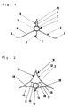
- the heat exchanger element according to FIG. 1 consists of an extruded aluminum profile 1, which is pushed coaxially onto a pipeline 2, with a heat exchange medium is applied.
- the aluminum extruded profile 1 has a bowl-shaped contact piece 3, the the outer radius of the pipe 2 is adapted.
- Two go from contact piece 3 roof-shaped mutually arranged profile parts 4, which at their diverging lower Merge ends into horizontally aligned longitudinal edge strips 5.
- profile parts 4 Between the profile parts 4 is a third profile part in the plane of the bisector 6 arranged that at its lower edge with a horizontally oriented longitudinal edge strip 7 completes.
- a hollow web 8 is formed, which includes an expansion joint 9. This enables an elastic expansion of the contact piece 3 due to an expansion of the pipeline 2, whereby the aluminum extrusion 1 exerted on the pipe 2 Contact pressure can be increased accordingly.
- the heat exchanger element shown in FIG. 2 consists of an extruded aluminum profile 11, which is also coaxial with a heat exchanger medium Pipe 2 is pushed on.
- the aluminum extruded profile 11 has three profile parts each forming a radiation surface 12, 12 and 13, which are arranged A-shaped to each other.
- the roof-shaped Profile parts 12, 12 have concave radiation surfaces, whereas this essentially horizontally aligned profile part 13 as the radiation surface of the pipeline immediately adjacent, externally convex contact piece 14 and laterally on it has subsequent concave side pieces 15.
- a contact piece 16 is formed on the inside of each profile part 12 via an intermediate piece 17.
- the inside concave contact piece 14 of the profile part 13 lies directly against the outside of the pipeline 2, so that when it is expanded Extruded aluminum profile 11 increasingly presses against the pipeline 2.
Landscapes
- Engineering & Computer Science (AREA)
- General Engineering & Computer Science (AREA)
- Mechanical Engineering (AREA)
- Physics & Mathematics (AREA)
- Chemical & Material Sciences (AREA)
- Combustion & Propulsion (AREA)
- Thermal Sciences (AREA)
- Sustainable Development (AREA)
- Life Sciences & Earth Sciences (AREA)
- Geometry (AREA)
- Heat-Exchange Devices With Radiators And Conduit Assemblies (AREA)
- Cooling Or The Like Of Semiconductors Or Solid State Devices (AREA)
- Extrusion Of Metal (AREA)
- Separation By Low-Temperature Treatments (AREA)
Abstract
Description
Die Erfindung betrifft ein Wärmetauscherelement aus einem Aluminium-Strangpreßprofil, worin mindestens eine mit einem Wärmetauschermedium beaufschlagbare Rohrleitung integrierbar ist. Die Mittelachse der Rohrleitung erstreckt sich in Längsrichtung des Aluminium-Strangpreßprofils, das mindestens ein dem Außenradius der Rohrleitung angepaßtes, schalenförmiges Kontaktstück aufweist.The invention relates to a heat exchanger element made of an extruded aluminum profile, wherein at least one can be acted upon with a heat exchange medium Pipeline can be integrated. The central axis of the pipeline extends in the longitudinal direction of the aluminum extrusion, which is at least one of the outer radius Has pipeline adapted, shell-shaped contact piece.
Derartige Wärmetauscherelemente sind beispielsweise aus dem DE-U- 93 15 709.6 als Deckenprofile für eine Kühldecke bekannt. Durch diese soll aufsteigende warme Raumluft an der Raumdecke abgekühlt werden. Die dort mögliche großflächige Kühlung erlaubt relativ niedrige Luftströmgeschwindigkeiten und vermindert somit die Hauptnachteile konventioneller Klimaanlagen, die in der Regel weder völlig geräuschlos noch gänzlich zugfrei betrieben werden können.Such heat exchanger elements are for example from DE-U-93 15 709.6 known as ceiling profiles for a chilled ceiling. This is said to ascend warm Indoor air to be cooled on the ceiling. The possible large-area cooling there allows relatively low airflow speeds and thus reduces the main disadvantages conventional air conditioners, which are usually neither completely silent yet can be operated entirely without a train.
Die als Deckenprofile für eine Kühldecke ausgebildeten bekannten Wärmetauscherelemente sind jeweils mit einem Stegabschnitt versehen, an welchem eine Haltevorrichtung angeformt ist, mit der das Wärmetauscherelement an einem Kühlrohr befestigt werden kann. Von den Längskanten des Stegabschnitts sind Schenkelabschnitte abgewinkelt. Dabei ist einer der zwei Schenkelabschnitte als Luftleitschenkel so in Richtung eines in Einbauposition nächstliegenden Wärmetauscherelements geneigt, daß zwischen den Deckenprofilen ein Luftkanal in Richtung auf das über dem nächstliegenden Wärmetauscherelement liegende Kühlrohr gebildet wird.The known heat exchanger elements designed as ceiling profiles for a chilled ceiling are each provided with a web section on which a holding device is molded with which the heat exchanger element is attached to a cooling tube can be. From the longitudinal edges of the web section are leg sections angled. One of the two leg sections is thus in the form of an air guide leg Inclined in the direction of a heat exchanger element closest in the installation position, that between the ceiling profiles an air duct in the direction of the one above Heat exchanger element lying cooling tube is formed.
Mit der Ausbildung der die Kühlrohre verblendenden Wärmetauscherelemente als Luftleitprofile wird angestrebt, eine besonders effektive großflächige und zugfreie Abführung hoher Wärmelasten aus dem zu kühlenden Raum durch konvektiven Wärmetransport zu ermöglichen. With the formation of the heat exchanger elements that cover the cooling tubes as air guide profiles is aimed at a particularly effective large-area and draft-free discharge high heat loads from the room to be cooled through convective heat transport to enable.
Ein wesentlicher Nachteil der bekannten Wärmetauscherelemente ist darin zu sehen, daß ihre Verwendbarkeit als Kühldeckenelemente deshalb begrenzt ist, weil ihre relativ große Bauhöhe entsprechend große lichte Zwischendeckenräume erfordert. Die Einsatzmöglichkeiten sind daher von relativ großen Geschoßhöhen abhängig.A major disadvantage of the known heat exchanger elements is that that their usability as chilled ceiling elements is limited because their relative large overall height requires large clear false ceiling spaces. The possible uses are therefore dependent on relatively large storey heights.
Ein weiterer Nachteil der bekannten Wärmetauscherelemente zeigt sich, wenn deren Länge bei ansonsten üblicher Dimensionierung 2 m überschreitet. In diesen Fällen kommt es zu einem optisch unschönen Durchhängen der Wärmetauscherelemente, was sich nur durch besondere, aufwendige Vorkehrungen kompensieren läßt. Die bei Wärmetauscherelementen, welche eine Länge von 2 m überschreiten, erforderliche Unterstützung ist nicht nur sehr aufwendig, sondern wirkt sich in der Regel auch optisch nachteilig aus.Another disadvantage of the known heat exchanger elements can be seen when they are Length exceeds 2 m with the usual dimensioning. In these cases there is an optically unsightly sagging of the heat exchanger elements, which can only be compensated for by special, complex precautions. The at Heat exchanger elements that exceed a length of 2 m are required Support is not only very complex, but usually also has an optical effect disadvantageous.
Schließlich besteht bei der bestimmungsgemäßen Anordnung der bekannten Wärmetauscherelemente die Gefahr, daß die kältesten Teilflächen der Elemente von Teilen benachbarter Elemente überdeckt werden. Der Strahlungswärmetausch zum Raum kann dabei gänzlich unterbunden werden oder nur unter sehr ungünstigen Einstrahlwinkeln möglich sein. Der Anteil des Strahlungswärmeaustausches an der Gesamtleistung ist folglich nicht optimal.Finally, in the intended arrangement of the known heat exchanger elements the risk of the coldest faces of the elements of parts neighboring elements are covered. The radiant heat exchange to the room can be completely prevented or only under very unfavorable angles of incidence to be possible. The share of radiant heat exchange in the total output is therefore not optimal.
Der Erfindung liegt die Aufgabe zugrunde, ein Wärmetauscherelement der eingangs beschriebenen Art so auszubilden, daß es die vorstehend angesprochenen Nachteile nicht aufweist und sich insbesondere auch durch eine große Biegesteifigkeit auszeichnet, ohne zusätzliche, die Stabilität erhöhende Bauteile zu benötigen.The invention has for its object a heat exchanger element of the beginning type described so that it has the disadvantages mentioned above does not have and is also characterized in particular by great flexural rigidity, without the need for additional components that increase stability.
Ausgehend von einem Wärmetauscherelement der im Oberbegriff des Patentanspruchs 1 genannten Art, wird diese Aufgabe erfindungsgemäß durch die im kennzeichnenden Teil des Patentanspruchs 1 angegebenen Merkmale gelöst. Starting from a heat exchanger element in the preamble of the claim 1 mentioned type, this object is achieved by the in the characterizing Part of claim 1 specified features solved.
Das erfindungsgemäße Wärmetauscherelement erhält durch die Anordnung der die Strahlungsfläche bildenden Profilteile zueinander eine stemförmige Kontur und zeichnet sich infolgedessen durch eine hohe Biegesteifigkeit, eine geringe Bauhöhe und eine große Wärmeübertragungsfläche mit entsprechender Wärmeübertragungsleistung aus. Das Wärmetauscherelement läßt sich als Aluminium-Strangpreßprofil in Längen bis zu 4 m herstellen. Derartig lange Wärmetauscherelemente senken den Fertigungs-, Montage- und Installationsaufwand gegenüber konventionellen Wärmetauscherelementen erheblich.The heat exchanger element according to the invention receives the by the arrangement of the Radiation area forming profile parts to each other a stem-shaped contour and draws as a result of its high bending stiffness, low overall height and a large heat transfer area with appropriate heat transfer capacity. The heat exchanger element can be an extruded aluminum profile in lengths up to Make 4 m. Such long heat exchanger elements reduce the manufacturing, assembly and installation effort compared to conventional heat exchanger elements considerably.
Die Wärmeübertragungsflächen des erfindungsgemäßen Wärmetauscherelements sind wesentlich größer als dessen Projektionsfläche. Da das Wärmetauscherelement mit seinen kältesten Teilflächen direkt zum Aufenthaltsbereich des Raumes ausgerichtet werden kann, läßt sich ein großer Anteil Strahlungswärmeaustausch an der Gesamtleistung erzielen. Schließlich tragen die guten konvektiven Wärmeübertragungsbedingungen des erfindungsgemäßen Wärmetauscherelements zu der hohen Gesamtleistung bei.The heat transfer surfaces of the heat exchanger element according to the invention are much larger than its projection area. Since the heat exchanger element with its coldest parts directly aligned with the lounge area of the room can be a large share of radiant heat exchange in the total output achieve. Finally, the good convective heat transfer conditions contribute of the heat exchanger element according to the invention high overall performance.
Nach einer Ausgestaltung der Erfindung ist durch gegenüberliegende Längsrandstreifen der schalenförmigen Kontaktstücke mindestens eine Dehnungsfuge begrenzt.According to one embodiment of the invention is through opposite longitudinal edge strips the cup-shaped contact pieces limited at least one expansion joint.
Die im Aluminium-Strangpreßprofil vorgesehene Dehnungsfuge zwischen den schalenförmigen Kontaktstücken ermöglich es, diese unter Vorspannung gegen die Rohrleitung zu pressen, wozu die Rohrleitung vorzugsweise geringfügig aufgeweitet wird, nachdem das Wärmetauscherelement auf die Rohrleitung aufgeschoben worden ist.The expansion joint provided in the extruded aluminum profile between the shell-shaped Contact pieces make it possible to pretension them against the pipeline to press, for which purpose the pipeline is preferably widened slightly after the heat exchanger element has been pushed onto the pipeline.
Nach einer besonders vorteilhaften Ausgestaltung des erfindungsgemäßen Wärmetauscherelements sind zwei mit je einer dem Raum zugewandten Strahlungsfläche versehene Profilteile dachförmig zueinander angeordnet und an ihren divergierenden unteren Enden mit horizontal ausgerichteten Längsrandstreifen versehen.According to a particularly advantageous embodiment of the heat exchanger element according to the invention are two with a radiation surface facing the room Profile parts arranged roof-shaped to each other and at their diverging lower Provide the ends with horizontally aligned longitudinal edge strips.
Zur Vergrößerung der Strahlungsflächen kann darüber hinaus zwischen den dachförmig zueinander angeordneten Profilteilen in der Ebene der Winkelhalbierenden ein drittes Profilteil angeordnet werden, das vorzugsweise mit einem horizontal ausgerichteten Längsrandstreifen abschließt.To increase the radiation area can also be roof-shaped mutually arranged profile parts in the plane of the bisector a third Profile part are arranged, preferably with a horizontally aligned Longitudinal edge strips complete.
Nach einer weiteren Ausgestaltung des erfindungsgemäßen Wärmetauscherelements ist auf der dem dritten Profilteil gegenüberliegenden Seite der Rohrleitung ein an einem schalenförmigen Kontaktstück angeformter Hohlsteg vorgesehen, der mit dem dritten Profilteil fluchtet.According to a further embodiment of the heat exchanger element according to the invention is on the opposite side of the pipeline to the third profile part bowl-shaped contact piece molded hollow bar provided with the third Profile part is aligned.
Der Hohlsteg umfaßt die Dehnungsfuge und ermöglicht es, in seinem oberen Ende einen in Längsrichtung des Profils verlaufenden Schraubkanal vorzusehen. Werden so ausgebildete Wärmetauscherelemente zwischen zwei gegenüberliegenden Rahmenschenkeln eines Rahmens angeordnet, wobei die Rahmenschenkel die Stimseiten der Profile abdecken, so lassen sich die Profile in einfacher Weise dadurch fixieren, daß durch entsprechend plazierte Bohrungen in den Rahmenschenkeln eingeführte Schraubenbolzen in die Schraubkanäle der Profile eingedreht werden.The hollow web encloses the expansion joint and enables one in its upper end screw channel running in the longitudinal direction of the profile. Be like that trained heat exchanger elements between two opposite frame legs a frame arranged, the frame legs the front sides of the Cover profiles, so the profiles can be easily fixed in that screw bolts inserted through correspondingly placed holes in the frame legs be screwed into the screw channels of the profiles.
Eine besonders vorteilhafte Ausgestaltung des erfindunsgemäßen Wärmetauscherelements sieht vor, daß drei je eine Strahlungsfläche bildende Profilteile Δ-förmig zueinander angeordnet sind.A particularly advantageous embodiment of the heat exchanger element according to the invention provides that three profile parts each forming a radiation surface are Δ-shaped to one another are arranged.
Die Δ-förmige Anordnung der drei Strahlungsflächen des Profil verleiht diesem nicht nur eine große Biegesteifigkeit, sondem erhöht auch die Verwindungssteifigkeit des Profils außerordentlich. The Δ-shaped arrangement of the three radiation surfaces of the profile not only gives this great bending stiffness, but also increases the torsional stiffness of the profile extraordinary.
Gemäß einer weiteren Ausgestaltung der Erfindung ist je eine Strahlungsfläche von zwei dachförmig zueinander ausgerichteten Profilteilen konkav und die Strahlungsfläche von einem horizontal ausgerichteten Profilteil über ein der Rohrleitung unmittelbar benachbartes Kontaktstück außenseitig konvex und über daran anschließende Seitenstücke außenseitig konkav ausgebildet.According to a further embodiment of the invention, a radiation area of two roof parts aligned to each other concave and the radiation surface from a horizontally oriented profile part via one directly adjacent to the pipeline Contact piece convex on the outside and over adjoining side pieces concave on the outside.
Das unmittelbar dem Rohr benachbarte Kontaktstück mit den daran sich anschließenden Seitenstücken des im wesentlichen horizontal ausgerichteten Profilteils bildet die kältesten Teilflächen, die direkt dem Raum zugewandt sind. Dadurch läßt sich ein maximaler Anteil Strahlungswärmeaustausch an der Gesamtleistung erzielen.The contact piece directly adjacent to the pipe with the adjoining ones Forms side pieces of the substantially horizontally oriented profile part the coldest areas that face the room directly. This allows one Achieve maximum share of radiant heat exchange in the total output.
Während das dem Aufenthaltsbereich eines Raumes zugewandte, im wesentlichen horizontal ausgerichtete Profilteil in unmittelbarem Kontakt mit dem Rohr steht und folglich die kältesten Teilflächen bildet, sind nach einer weiteren Ausgestaltung der Erfindung die zwei dachförmig zueinander angeordneten Profilteile über je ein Zwischenstück mit je einem schalenförmigen Kontaktstück verbunden. Über die Zwischenstücke, welche vorzugsweise bogenförmig verlaufen, lassen sich die schalenförmigen Kontaktstücke unter Vorspannung gegen die Rohrleitung pressen und begünstigen den Wärmeübergang von der Rohrleitung auf das Wärmetauscherelement.While that facing the lounge area of a room is essentially horizontal aligned profile part is in direct contact with the tube and consequently forms the coldest partial areas are according to a further embodiment of the invention the two roof-shaped profiles with each other with an intermediate piece each connected to a bowl-shaped contact piece. About the spacers, which The bowl-shaped contact pieces can preferably run in an arc shape press against the pipeline under pre-tension and promote heat transfer from the pipeline to the heat exchanger element.
Um auch Δ-förmig ausgebildete Wärmetauscherelemente verdrehfest auf einer Rohrleitung zwischen zwei Rahmenschenkeln fixieren zu können, sieht eine Ausgestaltung der Erfindung schließlich noch vor, daß in mindestens einem Eckbereich des Profils ein in Längsrichtung des Profils verlaufender Schraubkanal vorgesehen ist.To form Δ-shaped heat exchanger elements, they are torsion-proof on a pipeline To be able to fix between two frame legs sees an embodiment of the Finally, the invention proposes that in at least one corner region of the profile Longitudinal direction of the profile screw channel is provided.
Durch Bohrungen in den Rahmenschenkeln eingeführte Gewindebolzen lassen sich wiederum in die Schraubkanäle eindrehen und verhindem dadurch eine unbeabsichtigte Verdrehung der Wärmetauscherelemente um die durch die Rohrleitung definierte Achse.Threaded bolts inserted through holes in the frame legs can be again screw into the screw channels and thereby prevent unintentional Rotation of the heat exchanger elements by the one defined by the pipeline Axis.
In der Zeichnung sind zwei Ausführungsbeispiele je eines erfindungsgemäßen Wärmetauscherelements im Querschnitt dargestellt. Es zeigt:
- Fig. 1
- ein Wärmetauscherelement aus einem Aluminium-Strangpreß profil mit radial abstehenden Profilteilen
- Fig. 2
- ein Wärmetauscherelement aus einem Aluminium-Strangpreßprofil mit Δ-förmig zueinander angeordneten Profilteilen.
- Fig. 1
- a heat exchanger element made of an aluminum extrusion profile with radially protruding profile parts
- Fig. 2
- a heat exchanger element made of an extruded aluminum profile with Δ-shaped mutually arranged profile parts.
Das Wärmetauscherelement gemäß Fig. 1 besteht aus einem Aluminium-Strangpreßprofil
1, das koaxial auf eine Rohrleitung 2 aufgeschoben ist, die mit einem Wärmetauschermedium
beaufschlagt wird.The heat exchanger element according to FIG. 1 consists of an extruded aluminum profile
1, which is pushed coaxially onto a
Das Aluminium-Strangpreßprofil 1 weist ein schalenförmiges Kontaktstück 3 auf, das
dem Außenradius der Rohrleitung 2 angepaßt ist. Vom Kontaktstück 3 gehen zwei
dachförmig zueinander angeordnete Profilteile 4 aus, die an ihren divergierenden unteren
Enden in horizontal ausgerichtete Längsrandstreifen 5 übergehen.The aluminum extruded profile 1 has a bowl-
Zwischen den Profilteilen 4 ist in der Ebene der Winkelhalbierenden ein drittes Profilteil
6 angeordnet, das an seiner unteren Kante mit einem horizontal ausgerichteten Längsrandstreifen
7 abschließt. Between the
Auf der dem dritten Profilteil 6 gegenüberliegenden Seite der Rohrleitung 2 ist am Kontaktstück
ein Hohlsteg 8 angeformt, der eine Dehnfuge 9 einschließt. Diese ermöglicht
eine elastische Aufweitung des Kontaktstückes 3 infolge einer Aufweitung der Rohrleitung
2, wodurch sich die vom Aluminium-Strangpreßprofil 1 auf die Rohrleitung 2 ausgeübte
Anpreßkraft entsprechend erhöhen läßt.On the side of the
Im oberen Endbereich des Hohlsteges 8 ist ein in Längsrichtung des Aluminium-Strangpreßprofils
1 verlaufender Schraubkanal 10 vorgesehen, in den sich zur Fixierung
des Wärmetauscherelements innerhalb eines Rahmens ein von diesem ausgehender
Gewindebolzen eindrehen läßt.In the upper end region of the
Das Wärmetauscherelement gemäß Fig. 2 besteht aus einem Aluminium-Strangpreßprofil
11, das gleichfalls koaxial auf eine mit einem Wärmetauschermedium beaufschlagbare
Rohrleitung 2 aufgeschoben ist.The heat exchanger element shown in FIG. 2 consists of an
Das Aluminium-Strangpreßprofil 11 weist drei je eine Strahlungsfläche bildende Profilteile
12, 12 und 13 auf, die A-förmig zueinander angeordnet sind. Die dachförmig ausgerichteten
Profilteile 12, 12 weisen konkave Strahlungsflächen auf, wogegen das im wesentlichen
horizontal ausgerichtete Profilteil 13 als Strahlungsfläche ein der Rohrleitung
unmittelbar benachbartes, außen konvexes Kontaktstück 14 und jeweils seitlich daran
anschließende, konkave Seitenstücke 15 aufweist.The aluminum extruded
An jedem Profilteil 12 ist innenseitig ein Kontaktstück 16 über ein Zwischenstück 17 angeformt.
Das innenseitig konkave Kontaktstück 14 des Profilteils 13 liegt unmittelbar
gegen die Außenseite der Rohrleitung 2 an, so daß sich bei deren Aufweitung das
Aluminium-Strangpreßprofil 11 zunehmend gegen die Rohrleitung 2 anpreßt. A
Im Übergangsbereich von dem Profilteil 12 zu dem Profilteil 13 sind gleichfalls an dem
Aluminium-Strangpreßprofil 11 in dessen Längsrichtung verlaufende Schraubkanäle 18
vorgesehen, in die sich wiederum zur Fixierung des Wärmetauscherelements innerhalb
eines Rahmens von diesem Bauteil ausgehende Gewindebolzen eindrehen
lassen.In the transition area from the
Claims (10)
- Heat exchanger element of an aluminium extrusion moulding profile into which is integrated at least one pipeline which is loaded by a heat exchanger medium, the centre axis of which extends in the longitudinal direction of the profile which comprises at least one cupshaped contact piece which is matched with the outside radius of the pipeline, characterised by at least one profile part (4, 6, 8 or 12, 13) which is formed onto each contact piece (3, 14, 16) at its side facing away from the pipeline (2) and establishes a radiation surface, and the course from the outer longitudinal edges of the profile parts is defined by the corner points of a triangle.
- Heat exchanger element according to Claim 1, characterised in that at least one expansion gap (9) is defined by oppositely positioned longitudinal edge strips of the cupshaped contact pieces (3, 14, 16).
- Heat exchanger element according to Claim 1 or 2, characterised in that two profile parts (4), which are each provided with a radiation surface with is facing the area, are configured rooflike relative to each other and are at their diverging lower ends provided with horizontally aligned longitudinal edge strips (5).
- Heat exchanger element according to Claim 3, characterised in that between the profile parts (4), which are configured rooflike relative to each other, in the plane of the bisector of an angle is configured a third profile part (6) which terminates in a horizontally aligned longitudinal edge strip (7).
- Heat exchanger element according to Claim 4, characterised in that at the side of the pipeline (2) positioned opposite the third profile part (6) is provided a hollow web (8), which is formed onto a cupshaped contact piece and which is flush with the third profile part (6).
- Heat exchanger element according to Claim 5, characterised in that in the upper end of the hollow web (8) is provided a screw channel (10) which extends in the longitudinal direction of the profile (1).
- Heat exchanger element according to Claim 1 or 2, characterised in that three profile parts (12, 12, 13), which each form a radiation surface, are A-shaped relative to each other.
- Heat exchanger element according to Claim 7, characterised in that one each radiation surface is formed concave by two profile parts (12, 12), which are configured rooflike relative to each other, and the radiation surface is formed by a horizontally aligned profile part (13) via a contact piece (14), which is directly adjacent to the pipeline (2), externally convex and externally concave via thereto adjacent side pieces.
- Heat exchanger element according to Claim 8, characterised in that the two profile parts (12), which are configured rooflike relative to each other, are joined to a respective cupshaped contact piece (16) via a respective intermediate piece (17).
- Heat exchanger element according to one of Claims 7 to 9, characterised in that in at least one comer area of the profile (11) is provided a screw channel (18) which extends in the longitudinal direction of the profile.
Applications Claiming Priority (2)
| Application Number | Priority Date | Filing Date | Title |
|---|---|---|---|
| DE19615419A DE19615419C1 (en) | 1996-04-19 | 1996-04-19 | Extruded aluminium heat exchanger element with integrated pipe |
| DE19615419 | 1996-04-19 |
Publications (3)
| Publication Number | Publication Date |
|---|---|
| EP0802376A2 EP0802376A2 (en) | 1997-10-22 |
| EP0802376A3 EP0802376A3 (en) | 1998-10-21 |
| EP0802376B1 true EP0802376B1 (en) | 1999-06-23 |
Family
ID=7791694
Family Applications (1)
| Application Number | Title | Priority Date | Filing Date |
|---|---|---|---|
| EP97105332A Expired - Lifetime EP0802376B1 (en) | 1996-04-19 | 1997-03-29 | Heat exchanger element made of an extruded bar of aluminium |
Country Status (4)
| Country | Link |
|---|---|
| EP (1) | EP0802376B1 (en) |
| AT (1) | ATE181594T1 (en) |
| DE (2) | DE19615419C1 (en) |
| ES (1) | ES2134042T3 (en) |
Families Citing this family (13)
| Publication number | Priority date | Publication date | Assignee | Title |
|---|---|---|---|---|
| EP1061309A1 (en) * | 1999-06-16 | 2000-12-20 | Frans van Zaal B.V. | A method for the manufacture of a heating pipe, cooling pipe or cultivating through provided with a pipe |
| NL1013391C2 (en) * | 1999-10-26 | 2001-05-01 | Frans Van Zaal B V | Manufacturing method for heating pipe, cooling pipe or cultivating through provided with pipe, by forming section around pipe, such that section surrounds pipe and connects to it |
| DE20106951U1 (en) * | 2001-04-21 | 2001-07-05 | Ingenieurbüro Timmer Reichel GmbH, 42781 Haan | Room temperature control element |
| DE10328288A1 (en) * | 2003-06-23 | 2005-01-20 | Vasco Bvba | Profile body with longitudinal ribs and partial ribs |
| MXPA06007633A (en) * | 2006-06-30 | 2008-01-07 | Alejandro Cortina Cordero | Climate conditioning apparatus. |
| DE102008020422B4 (en) | 2008-04-24 | 2018-02-15 | Phoenix Metall Gmbh | Heating or cooling element with a connection piping |
| US9816709B2 (en) * | 2013-02-27 | 2017-11-14 | Gray Metal Products, Inc. | Retaining panel for radiant thermal transfer and method |
| DE102017130081A1 (en) | 2017-12-15 | 2019-06-19 | Krantz Gmbh | Device for tempering a room |
| DE102017130090A1 (en) | 2017-12-15 | 2019-06-19 | Krantz Gmbh | Device and method for tempering a room |
| PL4089335T3 (en) * | 2021-05-14 | 2024-05-20 | Allfest Gmbh | Ceiling radiator having a star-shaped cross-section |
| AT17598U1 (en) * | 2021-06-29 | 2022-08-15 | B M Newtec Gmbh | Cladding system with heating and/or cooling device |
| CN115638468B (en) * | 2022-10-31 | 2024-11-19 | 珠海格力电器股份有限公司 | Air conditioner internal unit and air conditioner |
| DE102023127521A1 (en) | 2023-10-09 | 2025-04-10 | Krantz Gmbh | Device for controlling the temperature of a room |
Family Cites Families (6)
| Publication number | Priority date | Publication date | Assignee | Title |
|---|---|---|---|---|
| GB289927A (en) * | 1927-01-31 | 1928-04-30 | Joseph Leslie Musgrave | Improvements in connection with the heating and cooling of buildings |
| FR1111140A (en) * | 1954-08-20 | 1956-02-22 | Heating or cooling ceiling | |
| FR1182273A (en) * | 1957-05-06 | 1959-06-24 | Heated baseboard and cornice | |
| DE1922977A1 (en) * | 1969-05-06 | 1970-12-23 | Schneider Anton Michael | Radiation plate for space heating and bracket in addition |
| NL8003116A (en) * | 1980-05-29 | 1982-01-04 | Alcoa Nederland Bv | Greenhouse heating pipe construction - is aluminium extrusion with wings joining onto tubular portion |
| DE9315709U1 (en) * | 1993-06-07 | 1994-02-10 | ZENT - FRENGER - Strahlungsheizungs-Gesellschaft mbH, 64646 Heppenheim | Ceiling profile for a chilled ceiling and chilled ceiling |
-
1996
- 1996-04-19 DE DE19615419A patent/DE19615419C1/en not_active Expired - Fee Related
-
1997
- 1997-03-29 AT AT97105332T patent/ATE181594T1/en not_active IP Right Cessation
- 1997-03-29 EP EP97105332A patent/EP0802376B1/en not_active Expired - Lifetime
- 1997-03-29 ES ES97105332T patent/ES2134042T3/en not_active Expired - Lifetime
- 1997-03-29 DE DE59700223T patent/DE59700223D1/en not_active Expired - Fee Related
Also Published As
| Publication number | Publication date |
|---|---|
| EP0802376A2 (en) | 1997-10-22 |
| ES2134042T3 (en) | 1999-09-16 |
| ATE181594T1 (en) | 1999-07-15 |
| DE19615419C1 (en) | 1997-06-05 |
| EP0802376A3 (en) | 1998-10-21 |
| DE59700223D1 (en) | 1999-07-29 |
Similar Documents
| Publication | Publication Date | Title |
|---|---|---|
| EP0802376B1 (en) | Heat exchanger element made of an extruded bar of aluminium | |
| EP0754824A1 (en) | Roof structure with canvas panels and a plurality of lattice girders to receive the canvas panels in between as well as a lattice girder for such a roof structure | |
| DE69412458T2 (en) | RADIATOR SYSTEM | |
| DE2630524A1 (en) | PLATE-SHAPED HEATING ELEMENTS ASSEMBLED FROM SEVERAL EXTRUDED ALUMINUM PROFILES | |
| DE3538188A1 (en) | Coupled element of two connected profile elements | |
| DE3704699C2 (en) | ||
| DE602004008585T2 (en) | LONG HOLDING ELEMENT FOR BUILDING PLATES | |
| EP1081300A2 (en) | Building | |
| DE10200527C2 (en) | balcony | |
| EP0994310A1 (en) | Tube holder | |
| DE9102260U1 (en) | Cooling ceiling for room air cooling | |
| DE19828188C1 (en) | Facade profile | |
| DE9315709U1 (en) | Ceiling profile for a chilled ceiling and chilled ceiling | |
| DE3140290A1 (en) | Wall element made of individual panels | |
| DE29614812U1 (en) | Fastening device | |
| EP1191294B1 (en) | Drying plant construction using panels | |
| DE10208687A1 (en) | Rooflight element overlap and join is bolted and stiffened by hollow rectangular section with surmounted centered profile parts engagingly anchored in element and all screwed down onto roof beams. | |
| DE20300135U1 (en) | Holder for double glazing panels at angle to each other in e.g. walls or roofs, has curved arm for inserting into groove in panel | |
| DD296135A5 (en) | COMPOUND SUPPORT FOR FIXING FRAME STRUCTURES | |
| DE19519187C2 (en) | Indoor chilled ceiling | |
| DE2915276A1 (en) | Crescent shaped bars joining panel type elements - have offset arcs bounding curved profile pieces, and end claws on bolts | |
| DE2913598A1 (en) | Room temp. control equipment - has pipes for heat conductive liq. fixed to metal framework of building | |
| DE8607498U1 (en) | Sealing strip | |
| DE2934098A1 (en) | Central heating pipe double T-fitting for shallow floor cavity - has double-ended pipe sockets connected by rectangular section tube to form H=shaped assembly | |
| DE10315774B3 (en) | Profile segment for supply unit has fixing element with at least two vertically separated supports, each with a longitudinal groove and a protrusion outboard of the groove |
Legal Events
| Date | Code | Title | Description |
|---|---|---|---|
| PUAI | Public reference made under article 153(3) epc to a published international application that has entered the european phase |
Free format text: ORIGINAL CODE: 0009012 |
|
| AK | Designated contracting states |
Kind code of ref document: A2 Designated state(s): AT CH DE ES FR GB IT LI NL |
|
| PUAL | Search report despatched |
Free format text: ORIGINAL CODE: 0009013 |
|
| AK | Designated contracting states |
Kind code of ref document: A3 Designated state(s): AT CH DE ES FR GB IT LI NL |
|
| GRAG | Despatch of communication of intention to grant |
Free format text: ORIGINAL CODE: EPIDOS AGRA |
|
| 17P | Request for examination filed |
Effective date: 19980917 |
|
| GRAG | Despatch of communication of intention to grant |
Free format text: ORIGINAL CODE: EPIDOS AGRA |
|
| GRAH | Despatch of communication of intention to grant a patent |
Free format text: ORIGINAL CODE: EPIDOS IGRA |
|
| 17Q | First examination report despatched |
Effective date: 19981113 |
|
| GRAH | Despatch of communication of intention to grant a patent |
Free format text: ORIGINAL CODE: EPIDOS IGRA |
|
| RAP1 | Party data changed (applicant data changed or rights of an application transferred) |
Owner name: KRANTZ - TKT GMBH |
|
| GRAA | (expected) grant |
Free format text: ORIGINAL CODE: 0009210 |
|
| AK | Designated contracting states |
Kind code of ref document: B1 Designated state(s): AT CH DE ES FR GB IT LI NL |
|
| REF | Corresponds to: |
Ref document number: 181594 Country of ref document: AT Date of ref document: 19990715 Kind code of ref document: T |
|
| REG | Reference to a national code |
Ref country code: CH Ref legal event code: NV Representative=s name: PATENTANWAELTE GEORG ROEMPLER UND ALDO ROEMPLER Ref country code: CH Ref legal event code: EP |
|
| REF | Corresponds to: |
Ref document number: 59700223 Country of ref document: DE Date of ref document: 19990729 |
|
| REG | Reference to a national code |
Ref country code: ES Ref legal event code: FG2A Ref document number: 2134042 Country of ref document: ES Kind code of ref document: T3 |
|
| GBT | Gb: translation of ep patent filed (gb section 77(6)(a)/1977) |
Effective date: 19990901 |
|
| ET | Fr: translation filed | ||
| PLBE | No opposition filed within time limit |
Free format text: ORIGINAL CODE: 0009261 |
|
| STAA | Information on the status of an ep patent application or granted ep patent |
Free format text: STATUS: NO OPPOSITION FILED WITHIN TIME LIMIT |
|
| 26N | No opposition filed | ||
| REG | Reference to a national code |
Ref country code: GB Ref legal event code: IF02 |
|
| PGFP | Annual fee paid to national office [announced via postgrant information from national office to epo] |
Ref country code: FR Payment date: 20020214 Year of fee payment: 6 |
|
| PGFP | Annual fee paid to national office [announced via postgrant information from national office to epo] |
Ref country code: ES Payment date: 20020221 Year of fee payment: 6 |
|
| PG25 | Lapsed in a contracting state [announced via postgrant information from national office to epo] |
Ref country code: ES Free format text: LAPSE BECAUSE OF NON-PAYMENT OF DUE FEES Effective date: 20030331 |
|
| PG25 | Lapsed in a contracting state [announced via postgrant information from national office to epo] |
Ref country code: FR Free format text: LAPSE BECAUSE OF NON-PAYMENT OF DUE FEES Effective date: 20031127 |
|
| REG | Reference to a national code |
Ref country code: FR Ref legal event code: ST |
|
| REG | Reference to a national code |
Ref country code: ES Ref legal event code: FD2A Effective date: 20030331 |
|
| PGFP | Annual fee paid to national office [announced via postgrant information from national office to epo] |
Ref country code: NL Payment date: 20050303 Year of fee payment: 9 |
|
| PGFP | Annual fee paid to national office [announced via postgrant information from national office to epo] |
Ref country code: DE Payment date: 20050308 Year of fee payment: 9 |
|
| PGFP | Annual fee paid to national office [announced via postgrant information from national office to epo] |
Ref country code: AT Payment date: 20050311 Year of fee payment: 9 |
|
| PGFP | Annual fee paid to national office [announced via postgrant information from national office to epo] |
Ref country code: GB Payment date: 20050323 Year of fee payment: 9 |
|
| PGFP | Annual fee paid to national office [announced via postgrant information from national office to epo] |
Ref country code: CH Payment date: 20050331 Year of fee payment: 9 |
|
| PG25 | Lapsed in a contracting state [announced via postgrant information from national office to epo] |
Ref country code: GB Free format text: LAPSE BECAUSE OF NON-PAYMENT OF DUE FEES Effective date: 20060329 Ref country code: AT Free format text: LAPSE BECAUSE OF NON-PAYMENT OF DUE FEES Effective date: 20060329 |
|
| PG25 | Lapsed in a contracting state [announced via postgrant information from national office to epo] |
Ref country code: LI Free format text: LAPSE BECAUSE OF NON-PAYMENT OF DUE FEES Effective date: 20060331 Ref country code: CH Free format text: LAPSE BECAUSE OF NON-PAYMENT OF DUE FEES Effective date: 20060331 |
|
| PGFP | Annual fee paid to national office [announced via postgrant information from national office to epo] |
Ref country code: IT Payment date: 20060331 Year of fee payment: 10 |
|
| PG25 | Lapsed in a contracting state [announced via postgrant information from national office to epo] |
Ref country code: NL Free format text: LAPSE BECAUSE OF NON-PAYMENT OF DUE FEES Effective date: 20061001 |
|
| PG25 | Lapsed in a contracting state [announced via postgrant information from national office to epo] |
Ref country code: DE Free format text: LAPSE BECAUSE OF NON-PAYMENT OF DUE FEES Effective date: 20061003 |
|
| REG | Reference to a national code |
Ref country code: CH Ref legal event code: PL |
|
| GBPC | Gb: european patent ceased through non-payment of renewal fee |
Effective date: 20060329 |
|
| NLV4 | Nl: lapsed or anulled due to non-payment of the annual fee |
Effective date: 20061001 |
|
| PG25 | Lapsed in a contracting state [announced via postgrant information from national office to epo] |
Ref country code: IT Free format text: LAPSE BECAUSE OF NON-PAYMENT OF DUE FEES Effective date: 20070329 |