EP0800941B1 - Methode und Einrichtung zum Steuerung eines Fahrzeug-Zusatzheizgeräts - Google Patents
Methode und Einrichtung zum Steuerung eines Fahrzeug-Zusatzheizgeräts Download PDFInfo
- Publication number
- EP0800941B1 EP0800941B1 EP97105689A EP97105689A EP0800941B1 EP 0800941 B1 EP0800941 B1 EP 0800941B1 EP 97105689 A EP97105689 A EP 97105689A EP 97105689 A EP97105689 A EP 97105689A EP 0800941 B1 EP0800941 B1 EP 0800941B1
- Authority
- EP
- European Patent Office
- Prior art keywords
- engine
- auxiliary heating
- heating system
- heat
- rotational speed
- Prior art date
- Legal status (The legal status is an assumption and is not a legal conclusion. Google has not performed a legal analysis and makes no representation as to the accuracy of the status listed.)
- Expired - Lifetime
Links
Images


Classifications
-
- F—MECHANICAL ENGINEERING; LIGHTING; HEATING; WEAPONS; BLASTING
- F01—MACHINES OR ENGINES IN GENERAL; ENGINE PLANTS IN GENERAL; STEAM ENGINES
- F01P—COOLING OF MACHINES OR ENGINES IN GENERAL; COOLING OF INTERNAL-COMBUSTION ENGINES
- F01P3/00—Liquid cooling
- F01P3/20—Cooling circuits not specific to a single part of engine or machine
-
- B—PERFORMING OPERATIONS; TRANSPORTING
- B60—VEHICLES IN GENERAL
- B60H—ARRANGEMENTS OF HEATING, COOLING, VENTILATING OR OTHER AIR-TREATING DEVICES SPECIALLY ADAPTED FOR PASSENGER OR GOODS SPACES OF VEHICLES
- B60H1/00—Heating, cooling or ventilating devices
- B60H1/02—Heating, cooling or ventilating devices the heat being derived from the propulsion plant
- B60H1/04—Heating, cooling or ventilating devices the heat being derived from the propulsion plant from cooling liquid of the plant
- B60H1/08—Heating, cooling or ventilating devices the heat being derived from the propulsion plant from cooling liquid of the plant from other radiator than main radiator
-
- B—PERFORMING OPERATIONS; TRANSPORTING
- B60—VEHICLES IN GENERAL
- B60H—ARRANGEMENTS OF HEATING, COOLING, VENTILATING OR OTHER AIR-TREATING DEVICES SPECIALLY ADAPTED FOR PASSENGER OR GOODS SPACES OF VEHICLES
- B60H1/00—Heating, cooling or ventilating devices
- B60H1/02—Heating, cooling or ventilating devices the heat being derived from the propulsion plant
- B60H1/03—Heating, cooling or ventilating devices the heat being derived from the propulsion plant and from a source other than the propulsion plant
- B60H1/038—Heating, cooling or ventilating devices the heat being derived from the propulsion plant and from a source other than the propulsion plant from the cooling liquid of the propulsion plant and from a viscous fluid heater
-
- F—MECHANICAL ENGINEERING; LIGHTING; HEATING; WEAPONS; BLASTING
- F24—HEATING; RANGES; VENTILATING
- F24V—COLLECTION, PRODUCTION OR USE OF HEAT NOT OTHERWISE PROVIDED FOR
- F24V40/00—Production or use of heat resulting from internal friction of moving fluids or from friction between fluids and moving bodies
-
- F—MECHANICAL ENGINEERING; LIGHTING; HEATING; WEAPONS; BLASTING
- F01—MACHINES OR ENGINES IN GENERAL; ENGINE PLANTS IN GENERAL; STEAM ENGINES
- F01P—COOLING OF MACHINES OR ENGINES IN GENERAL; COOLING OF INTERNAL-COMBUSTION ENGINES
- F01P2060/00—Cooling circuits using auxiliaries
- F01P2060/18—Heater
Definitions
- the present invention relates to a method and an apparatus for controlling the operation of an auxiliary heating system of a vehicle.
- a conventional auxiliary heating system is disclosed in Japanese Unexamined Patent Publication No. 2-254010.
- a viscous heater for generating heat by agitating viscous fluid is used as the auxiliary heating system.
- the viscous heater is driven by an engine through an electromagnetic clutch.
- a coolant temperature sensor is located in a coolant passage.
- An electromagnetic coil in the electromagnetic clutch receives energization control from a controller in accordance with the coolant temperature detected by the coolant temperature sensor. When the coolant temperature is equal to or lower than a set value, the viscous heater generates heat because the electromagnetic coil is energized and the electromagnetic clutch engages.
- the viscous heater When the coolant temperature is equal to or higher than the set value, the viscous heater does not generate heat because the electromagnetic coil is not energized and, the electromagnetic clutch is disengaged. That is, when the temperature of coolant heated by the heat of the engine is too low to heat the inside of the vehicle, the viscous heater generates heat to assist the heating of the inside of the vehicle.
- JP-60-113722 shows a method and apparatus for controlling the operation of an auxiliary heating system incorporating all the features of the preamble of claims 1 and 4, respectively. It differs by the switching conditions.
- the present invention can be implemented in numerous ways, including as a method and an apparatus.
- the present invention relates to a method for controlling an auxiliary heating system for a vehicle characterized by the features of the characterizing portion of claim 1.
- the present invention also relates to an auxiliary heating control apparatus for a vehicle, characterized by the features of the characterizing portion of claim 4.
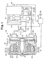
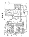
- a vehicle engine 11 is cooled by the coolant circulated through a passage 13 by a water pump 12. Heat is removed from the coolant circulated through the passage 13 with a conventional radiator 14.
- a electric cooling fan 15 assists in cooling the radiator 14.
- the passage 13 is provided with first and second auxiliary passages 131 and 132 and the first auxiliary passage 131 is provided with a temperature sensor 17.
- the temperature sensor 17 detects the temperature of the coolant flowing through the first auxiliary passage 131.
- a controller 18 controls the operation of the cooling fan 15 in accordance with the temperature data detected by the temperature sensor 17. When the coolant temperature detected by the temperature sensor 17 does not reach a predetermined coolant temperature, the controller 18 does not operate the cooling fan 15; whereas when the detected coolant temperature reaches the predetermined coolant temperature, the controller 18 operates the cooling fan 15.
- a radiator 16 is set to the second auxiliary passage 132. Heat is removed from the coolant flowing through the second auxiliary passage 132 due to the heat transfer effect of air from cooling fan 19 flowing through the radiator 16.
- the cooling fan 19 operates when a main heating switch 20 is turned on and the hot air from the radiator 16 is sent to the inside of the vehicle.
- a radiator 21 and a viscous heater 22 are connected to the first auxiliary passage 131. Heat is removed from the coolant flowing through the first auxiliary passage 13 due to the heat transfer effect of air from cooling fan 23 flowing through the radiator 21.
- the cooling fan 23 is controlled by an auxiliary heating controller 24.
- An auxiliary heating system comprises the radiator 21, the viscous heater 22, the cooling fan 23, and the auxiliary heating controller 24.
- a partition plate 27 having very high heat conductivity is located between a front housing 25 and a rear housing 26.
- the rear housing 26 is fixed to the front housing 25 by a bolt 28, which passes through the partition plate 27.
- the front housing 25 has a support cylinder 251.
- a heat generating chamber 29 is formed between the partition plate 27 and the front housing 25, and a water jacket 30 is formed between the partition plate 27 and the rear housing 26.
- the water jacket 30 is connected to the auxiliary passage 131 through an incoming-water port 261 and an outgoing-water port 262. Coolant moved from the engine 11 in the auxiliary passage 131 comes into the water jacket 30 from the incoming-water port 261 and goes out from the outgoing-water port 262. The water exiting going from the water jacket 30 flows to the radiator 21.
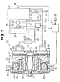
- a rotary shaft 31 is rotatably supported by the front housing 25 through a radial bearing 32.
- a rotor 33 having a disc shape is secured to the distal end of the rotary shaft 31.
- the rotor 33 is located in the heat generating chamber 29.
- Viscous fluid made of silicone oil is sealed in the heat generating chamber 29.
- a sealing mechanism 34 is provided between the front housing 25 and the rotary shaft 31 to prevent the viscous fluid from leaking.
- An electromagnetic clutch 35 is located on the outer periphery of the support cylinder 251.
- the electromagnetic clutch 35 has a pulley 351, which is rotatably supported by the support cylinder 251 through an angular bearing 37.
- the pulley 351 serves as a first clutch plate of the electromagnetic clutch 35, to which the driving force of the engine 11 is transferred through a belt 36.
- a support ring 38 is secured to the proximal end of the rotary shaft 31.
- a second clutch plate 352 of the electromagnetic clutch 35 is supported by the support ring 38 through a leaf spring 353.
- the electromagnetic clutch 35 has a solenoid 354 which is controlled by the auxiliary heating controller 24.
- the solenoid 354 When the solenoid 354 is excited, the clutch plate 352 is contacts the rear face of the pulley 351 against the spring force of the leaf spring 353 as shown in Figure 2.
- the clutch plate 352 is separated from the rear face of the pulley 351 by the spring force of the leaf spring 353 as shown in Figure 1.
- the rotational speed of the engine 11 is detected by an engine speed detector 40.
- the auxiliary heating controller 24 energizes the electromagnetic clutch 35 in accordance with the engine speed information sent from the engine speed detector 40 when an auxiliary heating switch 39 is turned on.
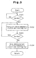
- FIG. 3 is a flow chart showing the energization control process for the electromagnetic clutch 35 and the cooling fan 23 by the auxiliary heating controller 24.
- the engine 11 is started while the auxiliary heating switch 39 is turned on.
- the rotational speed of the engine 11 is detected by the engine speed detector 40, which outputs engine speed information to the auxiliary heating controller 24.
- step S101 the auxiliary heating controller 24 determines whether a rotational speed Nx of the engine 11 has reached a preset rotational speed No.
- the electromagnetic clutch 35 and the cooling fan 23 are energized in step S102. That is, the solenoid 354 is excited and the clutch plate 352 is engaged with the pulley 351 as shown in Figure 2.
- the electromagnetic clutch 35 When the electromagnetic clutch 35 is engaged, the driving force of the engine 11 is transferred to the rotary shaft 31 through the belt 36, pulley 351, clutch plate 352, and support ring 38, and therefore, the rotor 33 is driven.
- the viscous fluid in the heat generating chamber 29 is agitated due to the rotation of the rotor 33 and heat is generated due to the agitation of the fluid.
- the generated heat is transferred to the water in the water jacket 30 through the partition plate 27, and the water in the water jacket 30 is heated and subsequently exit from the outgoing-water port 262.
- the heated water moves to the radiator 21, heat is removed from the heated water by the cooling fan 23 and the inside of the vehicle is heated by the heat.
- step S103 the auxiliary heating controller 24 determines whether the rotational speed Nx of the engine 11 exceeds the preset rotational speed No. While the engine 11 operates, the rotational speed Nx of the engine 11 exceeds the preset rotational speed No. When the engine 11 is stopped, the rotational speed Nx of the engine 11 becomes less than the preset rotational speed No, and consequently, in step S103, "NO" is decided. Then, in step S104, energization of the electromagnetic clutch 35 and the cooling fan 23 is stopped. When the energization of the electromagnetic clutch 35 is stopped, the solenoid 354 is demagnetized. Then, as shown in Figure 1, the clutch plate 352 separates from the pulley 351. That is, the electromagnetic clutch 35 is disengaged. Because the electromagnetic clutch 35 is disengaged, the driving force of the engine 11 is not transferred to the rotary shaft 31, and thus the rotation of the rotor 33 stops.
- the electromagnetic clutch 35 which serves a torque transfer means, is not operated when the engine 11 starts, the driving force of the engine 11 is not transferred to the viscous heater 22. That is, when the engine 11 starts, the clutch plate 352 of the electromagnetic clutch 35 is separated from the pulley 351. Therefore, the engine 11 is easily started because the driving torque for driving the viscous heater 22 does not load the engine 11.
- the preset rotational speed No is preferably a rotational speed at which the engine is capable of running. Therefore, a rotational speed that is slightly lower than normal idling speed is preferable. Until the rotational speed of the engine 11 reaches the preset rotational speed No, the electromagnetic clutch 35 remains disengaged. The method of detecting the rotational speed of the engine 11 and performing energization control of the electromagnetic clutch 35 guarantees that the viscous heater 22 is not operated until the engine 11 is actually running.
- the viscous heater 22 has a high heat-generating efficiency and moreover, it is compact. However, viscous fluid that is not been agitated for a long time has a high viscosity, and therefore, the viscous heater 22 has a large initial load due to the initial viscosity. However, because the electromagnetic clutch 35 is disengaged when the engine 11 is started, the driving force of the engine 11 is not transferred to the viscous heater 22 when the viscous fluid has the maximum viscosity. Therefore, smooth starting of the engine 11 is possible despite the use of the viscous heater 22.
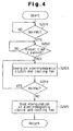
- step S201 the auxiliary heating controller 24 determines whether the rotational speed Nx of the engine 11 reaches the preset rotational speed No. When the controller 24 decides "YES", it process to decide in step S202 whether the rotational speed Nx of the engine 11 has reached a preset rotational speed Nx.
- step S202 When “YES" is decided in step S202, the process goes to step S203.
- steps S203 to S205 are the same as steps S102 to 5104 of the first embodiment.
- the electromagnetic clutch 35 remains disengaged until the rotational speed Nx of the engine 11 reaches the preset rotational speed No and further until a preset time t passes.
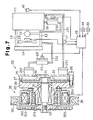
- an ignition switch 42 is connected to an auxiliary heating controller 41.
- the ignition switch 42 When the engine starting operation is initialized, the ignition switch 42 outputs a signal indicating that the engine 11 is being started to the auxiliary heating controller 41.
- the auxiliary heating controller 41 operates only when the auxiliary heating switch 39 is turned on.
- FIG. 6 is a flow chart showing the energization control of the electromagnetic clutch 35 and the cooling fan 23 by the auxiliary heating controller 41.
- the engine 11 is started while the auxiliary heating switch 39 is turned on.
- the auxiliary heating controller 41 determines whether a start signal is input.
- the auxiliary heating controller 41 decides "YES” in step S301, it proceeds to determine in step S302 whether a preset time t0 has passed after the input of the signal.
- step S303 is executed.
- the steps S303 to S305 are the same as steps S102 to S104 of the first embodiment.
- the preset time t0 is longer time than the time estimated for the engine 11 to reach a running start after the engine starting operation is initialized.
- the electromagnetic clutch 35 is disengaged until the preset time t0 passes after the initialization of starting the engine 11.
- the energization control for the cooling fans 15, 19, and 23 and the electromagnetic clutch 35 are performed by an auxiliary heating controller 43.
- the energization of the fan 19 is referred to as main energization.
- the energization of the clutch 35 and the fan 23 is referred to as auxiliary energization.
- the temperature sensor 17 and a heating switch 44 are connected to the auxiliary heating controller 43.
- the auxiliary heating controller 43 controls the operation of the cooling fan 15 in accordance with the detected coolant temperature information obtained from the temperature sensor 17.
- the auxiliary heating controller 41 becomes ready for control of the electromagnetic clutch 35 and the cooling fans 23 and 19 only while the auxiliary heating switch 39 is turned on.
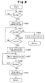
- Figure 8 is a flow chart showing the energization control of the electromagnetic clutch 35 and the cooling fans 23 and 19 by the auxiliary heating controller 43.
- the engine 11 is started while the auxiliary heating switch 39 is turned on.
- step S401 the auxiliary heating controller 43 determines whether the rotational speed Nx of the engine 11 has reached the preset rotational speed No.
- step S401 the auxiliary heating controller 43 performs auxiliary-energization of the electromagnetic clutch 35 and the cooling fan 23 in step S402.
- step S403 the auxiliary heating controller 43 determines again whether the rotational speed Nx of the engine 11 exceeds or is equal to the preset rotational speed speed No. That is, it is judged whether the rotation of the engine 11 has fallen after the electromagnetic clutch 35 and the cooling fan 23 were energized.
- step S404 step S404 is executed.
- step S405 the energization of the electromagnetic clutch 35 and the cooling fan 23 is stopped in step S405 because it is decided that the rotational speed Nx of the engine 11 has fallen below the preset rotational speed No.
- step S404 the auxiliary heating controller 43 determines whether a coolant temperature Tx detected by the temperature sensor 17 has reached a preset coolant temperature To.
- a coolant temperature Tx detected by the temperature sensor 17 reaches the present coolant temperature To.
- the auxiliary heating controller 43 stops the auxiliary-energization in step S406.
- the controller 43 continues the auxiliary-energization.
- step S407 the auxiliary heating controller 43 performs the main energization of the cooling fan 19. when the main energization is executed, the cooling fan 19 operates. Then, in step S408, the auxiliary heating controller 43 determines again whether the rotational speed Nx of the engine 11 is greater than or equal to the preset rotational speed No. When “YES” is decided in step S408, the auxiliary heating controller 43 continues the main energization. However, when "NO" is decided in step S408, the auxiliary heating controller 43 stops the main energization of the cooling fan 19 in step S409. That is, the energization of the fan 19 is stopped when the engine is stopped.
- the heating switch 44 When the heating switch 44 is turned on, the heating action is automatically changed from the auxiliary heating system to the main heating system, and therefore, the time and labor for changing the heating action from the auxiliary heating system to the main heating system can be omitted.
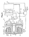
- This embodiment is different from the fourth embodiment in that the auxiliary passage 132, the radiator 16, and the cooling fan 19 are omitted.
- a heating controller 45 performs energization control of the electromagnetic clutch 35 and the cooling fan 23.
- the temperature sensor 17 outputs detected coolant temperature information to the heating controller 45.
- the heating controller 45 becomes ready for control only when the heating switch 44 is turned on.
- Figure 10 is a flow chart showing the energization control of the electromagnetic clutch 35 and the cooling fan 23 by the heating controller 45. In the routine shown by this flow chart, the operation for starting the engine 11 is performed while the auxiliary heating switch 39 is turned on.
- step S501 the heating controller 45 determines whether the rotational speed Nx of the engine 11 has reached the preset rotational speed No.
- the heating controller 45 energizes the electromagnetic clutch 35 and the cooling fan 23 in step S502.
- step S503 the heating controller 45 determines again whether the rotational speed Nx of the engine 11 is greater than or equal to the preset speed No. That is, it is judged whether, after the electromagnetic clutch 35 and the cooling fan 23 were energized, the rotation speed of the engine 11.
- step S504 is executed.
- step S504 energization of the electromagnetic clutch 35 and the cooling fan 23 is stopped because the rotational speed Nx of the engine 11 has fallen below the preset rotational speed No.
- step S504 the heating controller 45 determines whether the coolant temperature Tx detected by the temperature sensor 17 reaches the coolant temperature To.
- the heating controller 45 stops the energization of the electromagnetic clutch 35 in step S506.
- the controller 45 continues auxiliary-energization.
- step S507 the heating controller 45 determines again whether the rotational speed Nx of the engine 11 is equal to or greater than the preset rotational speed No.
- the heating controller 45 stops the energization of the cooling fan 23 in step S508.
- the radiator 21 and the cooling fan 23 also serve both as a part of an auxiliary heating system and a part of a main heating system.
- the heating switch 44 When the heating switch 44 is turned on, the heating action is automatically changed from the auxiliary heating system to the main heating system. Therefore, the time and labor for changing the heating action from the auxiliary heating system to the main heating system can be omitted.
- the radiator 21 and the cooling fan 23 serve as a part of an auxiliary heating system and a part of a main heating system, the entire of a heating system is simplified, and it reduces cost.
- the present invention can also be applied to a vehicle using an auxiliary heating system operated by the driving force of a vehicle engine via equipment such as a gear pump heater or eddy current heater.
Landscapes
- Engineering & Computer Science (AREA)
- Chemical & Material Sciences (AREA)
- Combustion & Propulsion (AREA)
- Mechanical Engineering (AREA)
- Physics & Mathematics (AREA)
- Thermal Sciences (AREA)
- General Engineering & Computer Science (AREA)
- Air-Conditioning For Vehicles (AREA)
- Structures Of Non-Positive Displacement Pumps (AREA)
Claims (9)
- Verfahren zum Steuern eines Hilfsheizsystems für ein Fahrzeug, wobei das Fahrzeug einen Verbrennungsmotor (11), ein Verbrennungsmotorkühlsystem (14) zum Heizen eines Kühlmittels, ein Fahrgastabteil (13, 131, 132), ein Hauptheizsystem (16) zum Heizen des Fahrgastabteils (13, 131, 132) unter Verwendung der Wärme von dem Kühlmittel und ein Hilfsheizsystem (22) hat, wobei das Hilfsheizsystem (22) die Antriebskraft des Verbrennungsmotors (11) zum Heizen des Kühlmittels getrennt von dem Verbrennungsmotorkühlsystem (14, 15) verwendet, wobei das Verfahren die folgenden Schritte aufweist:gekennzeichnet durchAbsperren der Übertragung der Antriebskraft des Verbrennungsmotors (11) auf das Hilfsheizsystem (21, 22), wenn der Verbrennungsmotor (11) gerade gestartet wird;Ermitteln der Drehzahl des Verbrennungsmotors;Übertragen der Antriebskraft des Verbrennungsmotors (11) auf das Hilfsheizsystem (21, 22), wenn der Verbrennungsmotor läuft;
Übertragen der Antriebskraft des Verbrennungsmotors (11) auf das Hilfsheizsystem (21, 22) nur dann, wenn eine vorbestimmte Zeitdauer verlaufen ist, nachdem der Verbrennungsmotor (11) die vorbestimmte Drehzahl erreicht hat. - Verfahren gemäß Anspruch 1,
gekennzeichnet durch
Erzeugen eines Startsignals, das anzeigt, dass der Verbrennungsmotor (11) gerade gestartet wird; und
Übertragen der Antriebskraft des Verbrennungsmotors (11) auf das Hilfsheizsystem (21, 22) nur dann, wenn eine vorbestimmte Zeitdauer abgelaufen ist, nachdem das Startsignal erzeugt wird. - Verfahren gemäß Anspruch 1,
dadurch gekennzeichnet, dass
das Hilfsheizsystem eine Viskositätsheizvorrichtung (22) zum Erzeugen von Wärme durch Bewegen eines viskosen Fluids aufweist. - Hilfsheizsteuerungsvorrichtung für ein Fahrzeug, wobei das Fahrzeug einen Verbrennungsmotor (11), ein Verbrennungsmotorkühlsystem (14) zum Heizen eines Kühlmittels, ein Fahrgastabteil (13, 131, 132), ein Hauptheizsystem (16) zum Heizen des Fahrgastabteils (13, 131, 132) unter Verwendung der Wärme von dem Kühlmittel und ein Hilfsheizsystem (22) hat, wobei das Hilfsheizsystem (22) die Antriebskraft des Verbrennungsmotors (11) zum Heizen des Kühlmittels getrennt von dem Verbrennungsmotorkühlsystem (14, 15) verwendet, wobei die Vorrichtung folgendes aufweist:wobei die Beurteilungseinrichtung (40) eine Drehzahlerfassungseinrichtung zum Erfassen der Drehzahl des Verbrennungsmotors aufweist;eine Drehmomentübertragungseinrichtung (35) zum Übertragen der Antriebskraft des Verbrennungsmotors (11) auf eine Wärmeerzeugungseinrichtung (22), wobei die Drehmomentübertragungseinrichtung (35) einen eingerückten Zustand, bei dem Antriebskraft des Verbrennungsmotors auf die Wärmeerzeugungseinrichtung (22) übertragen wird, und einen ausgerückten Zustand hat, bei dem die Wärmeerzeugungseinrichtung nicht betrieben wird;eine Einrichtung (40) zum Beurteilen, ob der Verbrennungsmotor eine vorbestimmte Betriebsbedingung erreicht hat,
eine Steuerungseinrichtung (24) zum Schalten der Drehmomentübertragungseinrichtung zwischen dem eingerückten Zustand und dem ausgerückten Zustand,
wobei die Steuerungseinrichtung die Drehmomentübertragungseinrichtung (35) zu dem eingerückten Zustand nur dann schaltet, wenn die Beurteilungseinrichtung (40) beurteilt, dass der Verbrennungsmotor(11) die vorbestimmte Betriebsbedingung erreicht hat;
dadurch gekennzeichnet, dass
die Steuerungseinrichtung die
Drehmomentübertragungseinrichtung (35) zu dem eingerückten Zustand frühestens dann schaltet, wenn der Verbrennungsmotor eine vorbestimmte Drehzahl erreicht. - Vorrichtung gemäß Anspruch 4,
dadurch gekennzeichnet, dass
die Steuerungseinrichtung (24) die Drehmomentübertragungseinrichtung (35) nur dann einrückt, wenn eine vorbestimmte Zeitdauer abgelaufen ist, nachdem der Verbrennungsmotor (11) die vorbestimmte Drehzahl erreicht hat. - Vorrichtung gemäß Anspruch 4,
gekennzeichnet durch
eine Einrichtung (42) zum Erzeugen eines Startsignals, das anzeigt, dass der Verbrennungsmotor (11) gerade gestartet wird, wobei die Steuerungseinrichtung (24) die Drehmomentübertragungseinrichtung (35) nur dann einrückt, wenn eine vorbestimmte Zeitdauer abgelaufen ist, nachdem das Startsignal erzeugt ist. - Vorrichtung gemäß Anspruch 4,
dadurch gekennzeichnet, dass
die Drehmomentübertragungseinrichtung eine elektromagnetische Kupplung (35) ist. - Vorrichtung gemäß Anspruch 4,
dadurch gekennzeichnet, dass
das Hilfsheizsystem eine Viskositätsheizvorrichtung (22) zum Erzeugen von Wärme durch Bewegen eines viskosen Fluids aufweist. - Vorrichtung gemäß Anspruch 8,
dadurch gekennzeichnet, dass
die Viskositätsheizvorrichtung (22) des Weiteren folgendes aufweist:eine Wärmeerzeugungskammer (29) zum Aufnehmen eines viskosen Fluids und eines Rotorelements (33);eine Wärmeaufnahmekammer (30) zum Aufnehmen von Wärme von der Wärmeerzeugungskammer (29) und zum Aufnehmen von zirkulierendem Kühlfluid; undein Gehäuse (25, 26) zum Einfassen der Wärmeerzeugungskammer (29) und einer Wärmeaufnahmekammer (30).
Applications Claiming Priority (3)
| Application Number | Priority Date | Filing Date | Title |
|---|---|---|---|
| JP8540696 | 1996-04-08 | ||
| JP85406/96 | 1996-04-08 | ||
| JP08540696A JP3215795B2 (ja) | 1996-04-08 | 1996-04-08 | 車両における補助暖房装置の運転制御方法及び装置 |
Publications (3)
| Publication Number | Publication Date |
|---|---|
| EP0800941A2 EP0800941A2 (de) | 1997-10-15 |
| EP0800941A3 EP0800941A3 (de) | 1999-06-09 |
| EP0800941B1 true EP0800941B1 (de) | 2003-07-02 |
Family
ID=13857924
Family Applications (1)
| Application Number | Title | Priority Date | Filing Date |
|---|---|---|---|
| EP97105689A Expired - Lifetime EP0800941B1 (de) | 1996-04-08 | 1997-04-07 | Methode und Einrichtung zum Steuerung eines Fahrzeug-Zusatzheizgeräts |
Country Status (7)
| Country | Link |
|---|---|
| US (1) | US5829675A (de) |
| EP (1) | EP0800941B1 (de) |
| JP (1) | JP3215795B2 (de) |
| KR (1) | KR100203005B1 (de) |
| CN (1) | CN1103703C (de) |
| CA (1) | CA2202022C (de) |
| DE (1) | DE69723142T2 (de) |
Families Citing this family (10)
| Publication number | Priority date | Publication date | Assignee | Title |
|---|---|---|---|---|
| KR20030088982A (ko) * | 2002-05-15 | 2003-11-21 | 기아자동차주식회사 | 자동차용 난방 시스템의 보조 히터 |
| JP4795332B2 (ja) * | 2004-02-26 | 2011-10-19 | ベンテック,エルエルシー | 乗り物補助加熱システム |
| US7735744B2 (en) * | 2004-03-11 | 2010-06-15 | Nissan Technical Center North America, Inc. | Control of coolant flow rate for vehicle heating |
| DE102004034243A1 (de) * | 2004-07-15 | 2006-02-09 | Webasto Ag | Kraftfahrzeugheizung sowie Verfahren zum Einschalten derselben |
| JP4459046B2 (ja) * | 2004-12-27 | 2010-04-28 | トヨタ自動車株式会社 | 自動車およびその制御方法 |
| US8480006B2 (en) * | 2006-09-08 | 2013-07-09 | Ventech, Llc | Vehicle supplemental heating system |
| US7686146B2 (en) * | 2006-09-27 | 2010-03-30 | Denso International America, Inc. | Combination viscous fan drive and viscous heat device |
| US9228760B2 (en) * | 2012-04-27 | 2016-01-05 | Mac, Inc. | Flameless heating system |
| US9682608B2 (en) * | 2013-01-30 | 2017-06-20 | Hanon Systems | Supplemental heating and cooling sources for a heating, ventilation and air conditioning system |
| US9995508B2 (en) * | 2014-11-18 | 2018-06-12 | Multitek North America, Llc | Systems for heating water used in hydraulic fracturing |
Family Cites Families (12)
| Publication number | Priority date | Publication date | Assignee | Title |
|---|---|---|---|---|
| DE3231903A1 (de) * | 1982-08-27 | 1984-03-01 | Robert Bosch Gmbh, 7000 Stuttgart | Heizeinrichtung |
| JPS60113722A (ja) * | 1983-11-26 | 1985-06-20 | Mazda Motor Corp | 暖房装置 |
| JPS60138822A (ja) * | 1983-12-27 | 1985-07-23 | Hitachi Ltd | 含浸形陰極 |
| JPS6130884A (ja) * | 1984-07-23 | 1986-02-13 | Matsushita Electric Ind Co Ltd | セグメント式vtr用シリンダ |
| FR2585635B1 (fr) * | 1985-07-30 | 1987-11-13 | Valeo | Generateur de chaleur pour vehicule automobile |
| FR2593750B1 (fr) * | 1986-02-03 | 1989-10-27 | Valeo | Generateur de chaleur a friction, notamment pour vehicule automobile |
| JP2712510B2 (ja) * | 1989-03-21 | 1998-02-16 | アイシン精機株式会社 | 車両用暖房装置 |
| JP2712516B2 (ja) * | 1989-03-28 | 1998-02-16 | アイシン精機株式会社 | 車両用暖房装置 |
| JPH07115581B2 (ja) * | 1989-07-25 | 1995-12-13 | アイシン精機株式会社 | 車両用暖房装置 |
| US5063513A (en) * | 1990-06-15 | 1991-11-05 | Nartron Corporation | Vehicle preheater control |
| JP3116589B2 (ja) * | 1992-09-16 | 2000-12-11 | 株式会社デンソー | 車両用暖房装置 |
| DE4420841A1 (de) * | 1994-06-15 | 1995-12-21 | Hans Dipl Ing Martin | Heizvorrichtung für Kraftfahrzeuge |
-
1996
- 1996-04-08 JP JP08540696A patent/JP3215795B2/ja not_active Expired - Fee Related
-
1997
- 1997-04-07 KR KR1019970012720A patent/KR100203005B1/ko not_active Expired - Fee Related
- 1997-04-07 DE DE69723142T patent/DE69723142T2/de not_active Expired - Fee Related
- 1997-04-07 CN CN97113405A patent/CN1103703C/zh not_active Expired - Fee Related
- 1997-04-07 EP EP97105689A patent/EP0800941B1/de not_active Expired - Lifetime
- 1997-04-07 CA CA002202022A patent/CA2202022C/en not_active Expired - Fee Related
- 1997-04-07 US US08/835,311 patent/US5829675A/en not_active Expired - Fee Related
Also Published As
| Publication number | Publication date |
|---|---|
| CN1174787A (zh) | 1998-03-04 |
| CN1103703C (zh) | 2003-03-26 |
| JPH09272326A (ja) | 1997-10-21 |
| DE69723142T2 (de) | 2004-05-27 |
| EP0800941A3 (de) | 1999-06-09 |
| US5829675A (en) | 1998-11-03 |
| DE69723142D1 (de) | 2003-08-07 |
| CA2202022C (en) | 2000-09-26 |
| KR970069442A (ko) | 1997-11-07 |
| KR100203005B1 (ko) | 1999-06-15 |
| CA2202022A1 (en) | 1997-10-08 |
| JP3215795B2 (ja) | 2001-10-09 |
| EP0800941A2 (de) | 1997-10-15 |
Similar Documents
| Publication | Publication Date | Title |
|---|---|---|
| JP4078742B2 (ja) | 車輌用暖房装置 | |
| EP0800941B1 (de) | Methode und Einrichtung zum Steuerung eines Fahrzeug-Zusatzheizgeräts | |
| US20080115745A1 (en) | Engine cooling system for vehicle | |
| EP1000787B1 (de) | Wärmepumpenartige Klimaanlage für ein Fahrzeug und Verfahren zur Korrosionsinhibierung und zum Erleichtern von Schnellerwärmung eines Fahrgastraumes während niedriger Temperaturen | |
| JPS60113017A (ja) | 二系統冷却式内燃機関の冷却ファンの運転制御方法 | |
| JPH0135166B2 (de) | ||
| US5906177A (en) | Vehicle heating system | |
| JP3116589B2 (ja) | 車両用暖房装置 | |
| EP1101915B1 (de) | Anlage und Verfahren zur Kühlung einer Brennkraftmaschine | |
| EP0841203A2 (de) | Heizeinrichtung für Fahrzeuge | |
| EP0573658A1 (de) | Verfahren zur verhinderung der entmagnetisierung und regelung für einen elektrischen motor | |
| JP2001341520A (ja) | 車両用暖房装置 | |
| JPH1178494A (ja) | 自動車用暖房装置 | |
| JP3175734B2 (ja) | 車両用暖房装置 | |
| JP2000108642A (ja) | 車両用暖房装置及びその制御方法 | |
| JPH10175419A (ja) | 車両用暖房装置 | |
| JPH10203142A (ja) | 車両用暖房装置 | |
| JPH10297265A (ja) | 車両用暖房装置 | |
| JP2000225837A (ja) | 車両用空調装置 | |
| JPH11263117A (ja) | 車両用補助暖房装置 | |
| JPH09315133A (ja) | 車両用暖房装置 | |
| JP2007186089A (ja) | 車両用機器の暖機装置 | |
| KR19980053078A (ko) | 차량용 라디에이터 냉각팬 제어장치 | |
| JP2001248440A (ja) | 液冷式内燃機関の冷却装置 | |
| KR20000032589A (ko) | 차량용 워터펌프의 마그네틱 풀리 장치 |
Legal Events
| Date | Code | Title | Description |
|---|---|---|---|
| PUAI | Public reference made under article 153(3) epc to a published international application that has entered the european phase |
Free format text: ORIGINAL CODE: 0009012 |
|
| 17P | Request for examination filed |
Effective date: 19970407 |
|
| AK | Designated contracting states |
Kind code of ref document: A2 Designated state(s): DE FR GB SE |
|
| PUAL | Search report despatched |
Free format text: ORIGINAL CODE: 0009013 |
|
| AK | Designated contracting states |
Kind code of ref document: A3 Designated state(s): DE FR GB SE |
|
| RAP1 | Party data changed (applicant data changed or rights of an application transferred) |
Owner name: DENSO CORPORATION Owner name: TOYOTA JIDOSHA KABUSHIKI KAISHA Owner name: KABUSHIKI KAISHA TOYOTA JIDOSHOKKI |
|
| 17Q | First examination report despatched |
Effective date: 20020129 |
|
| GRAH | Despatch of communication of intention to grant a patent |
Free format text: ORIGINAL CODE: EPIDOS IGRA |
|
| GRAH | Despatch of communication of intention to grant a patent |
Free format text: ORIGINAL CODE: EPIDOS IGRA |
|
| GRAA | (expected) grant |
Free format text: ORIGINAL CODE: 0009210 |
|
| AK | Designated contracting states |
Designated state(s): DE FR GB SE |
|
| REG | Reference to a national code |
Ref country code: GB Ref legal event code: FG4D |
|
| REG | Reference to a national code |
Ref country code: SE Ref legal event code: TRGR |
|
| REF | Corresponds to: |
Ref document number: 69723142 Country of ref document: DE Date of ref document: 20030807 Kind code of ref document: P |
|
| ET | Fr: translation filed | ||
| PLBE | No opposition filed within time limit |
Free format text: ORIGINAL CODE: 0009261 |
|
| STAA | Information on the status of an ep patent application or granted ep patent |
Free format text: STATUS: NO OPPOSITION FILED WITHIN TIME LIMIT |
|
| 26N | No opposition filed |
Effective date: 20040405 |
|
| PGFP | Annual fee paid to national office [announced via postgrant information from national office to epo] |
Ref country code: SE Payment date: 20090407 Year of fee payment: 13 Ref country code: FR Payment date: 20090417 Year of fee payment: 13 Ref country code: DE Payment date: 20090402 Year of fee payment: 13 |
|
| PGFP | Annual fee paid to national office [announced via postgrant information from national office to epo] |
Ref country code: GB Payment date: 20090401 Year of fee payment: 13 |
|
| EUG | Se: european patent has lapsed | ||
| GBPC | Gb: european patent ceased through non-payment of renewal fee |
Effective date: 20100407 |
|
| REG | Reference to a national code |
Ref country code: FR Ref legal event code: ST Effective date: 20101230 |
|
| PG25 | Lapsed in a contracting state [announced via postgrant information from national office to epo] |
Ref country code: DE Free format text: LAPSE BECAUSE OF NON-PAYMENT OF DUE FEES Effective date: 20101103 |
|
| PG25 | Lapsed in a contracting state [announced via postgrant information from national office to epo] |
Ref country code: GB Free format text: LAPSE BECAUSE OF NON-PAYMENT OF DUE FEES Effective date: 20100407 |
|
| PG25 | Lapsed in a contracting state [announced via postgrant information from national office to epo] |
Ref country code: FR Free format text: LAPSE BECAUSE OF NON-PAYMENT OF DUE FEES Effective date: 20100430 |
|
| PG25 | Lapsed in a contracting state [announced via postgrant information from national office to epo] |
Ref country code: SE Free format text: LAPSE BECAUSE OF NON-PAYMENT OF DUE FEES Effective date: 20100408 |