EP0800941B1 - Method and apparatus for controlling operation of auxiliary heating system of vehicle - Google Patents
Method and apparatus for controlling operation of auxiliary heating system of vehicle Download PDFInfo
- Publication number
- EP0800941B1 EP0800941B1 EP97105689A EP97105689A EP0800941B1 EP 0800941 B1 EP0800941 B1 EP 0800941B1 EP 97105689 A EP97105689 A EP 97105689A EP 97105689 A EP97105689 A EP 97105689A EP 0800941 B1 EP0800941 B1 EP 0800941B1
- Authority
- EP
- European Patent Office
- Prior art keywords
- engine
- auxiliary heating
- heating system
- heat
- rotational speed
- Prior art date
- Legal status (The legal status is an assumption and is not a legal conclusion. Google has not performed a legal analysis and makes no representation as to the accuracy of the status listed.)
- Expired - Lifetime
Links
Images


Classifications
-
- F—MECHANICAL ENGINEERING; LIGHTING; HEATING; WEAPONS; BLASTING
- F01—MACHINES OR ENGINES IN GENERAL; ENGINE PLANTS IN GENERAL; STEAM ENGINES
- F01P—COOLING OF MACHINES OR ENGINES IN GENERAL; COOLING OF INTERNAL-COMBUSTION ENGINES
- F01P3/00—Liquid cooling
- F01P3/20—Cooling circuits not specific to a single part of engine or machine
-
- B—PERFORMING OPERATIONS; TRANSPORTING
- B60—VEHICLES IN GENERAL
- B60H—ARRANGEMENTS OF HEATING, COOLING, VENTILATING OR OTHER AIR-TREATING DEVICES SPECIALLY ADAPTED FOR PASSENGER OR GOODS SPACES OF VEHICLES
- B60H1/00—Heating, cooling or ventilating [HVAC] devices
- B60H1/02—Heating, cooling or ventilating [HVAC] devices the heat being derived from the propulsion plant
- B60H1/04—Heating, cooling or ventilating [HVAC] devices the heat being derived from the propulsion plant from cooling liquid of the plant
- B60H1/08—Heating, cooling or ventilating [HVAC] devices the heat being derived from the propulsion plant from cooling liquid of the plant from other radiator than main radiator
-
- B—PERFORMING OPERATIONS; TRANSPORTING
- B60—VEHICLES IN GENERAL
- B60H—ARRANGEMENTS OF HEATING, COOLING, VENTILATING OR OTHER AIR-TREATING DEVICES SPECIALLY ADAPTED FOR PASSENGER OR GOODS SPACES OF VEHICLES
- B60H1/00—Heating, cooling or ventilating [HVAC] devices
- B60H1/02—Heating, cooling or ventilating [HVAC] devices the heat being derived from the propulsion plant
- B60H1/03—Heating, cooling or ventilating [HVAC] devices the heat being derived from the propulsion plant and from a source other than the propulsion plant
- B60H1/038—Heating, cooling or ventilating [HVAC] devices the heat being derived from the propulsion plant and from a source other than the propulsion plant from the cooling liquid of the propulsion plant and from a viscous fluid heater
-
- F—MECHANICAL ENGINEERING; LIGHTING; HEATING; WEAPONS; BLASTING
- F24—HEATING; RANGES; VENTILATING
- F24V—COLLECTION, PRODUCTION OR USE OF HEAT NOT OTHERWISE PROVIDED FOR
- F24V40/00—Production or use of heat resulting from internal friction of moving fluids or from friction between fluids and moving bodies
-
- F—MECHANICAL ENGINEERING; LIGHTING; HEATING; WEAPONS; BLASTING
- F01—MACHINES OR ENGINES IN GENERAL; ENGINE PLANTS IN GENERAL; STEAM ENGINES
- F01P—COOLING OF MACHINES OR ENGINES IN GENERAL; COOLING OF INTERNAL-COMBUSTION ENGINES
- F01P2060/00—Cooling circuits using auxiliaries
- F01P2060/18—Heater
Landscapes
- Engineering & Computer Science (AREA)
- Chemical & Material Sciences (AREA)
- Combustion & Propulsion (AREA)
- Mechanical Engineering (AREA)
- Physics & Mathematics (AREA)
- Thermal Sciences (AREA)
- General Engineering & Computer Science (AREA)
- Air-Conditioning For Vehicles (AREA)
- Structures Of Non-Positive Displacement Pumps (AREA)
Description
Claims (9)
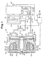
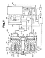
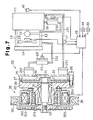
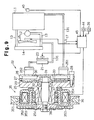
- A method for controlling an auxiliary heating system for a vehicle, the vehicle having an engine (11), an engine cooling system (14) for heating coolant, a passenger compartment (13,131,132), a main heating system (16) for heating the passenger compartment (13,131,132) using heat from the coolant, and an auxiliary heating system (22),
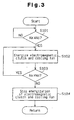
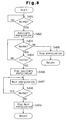
wherein the auxiliary heating system (22) uses the driving force of the engine (11) to heat the coolant separately from the engine cooling system (14,15), the method comprising the steps of:characterized bycutting off the transfer of the driving force of the engine (11) to the auxiliary heating system (21,22) when the engine (11) is being started;determining the rotational speed of the engine;transferring the driving force of the engine (11) to the auxiliary heating system (21, 22) when the engine is running;
transferring the driving force of the engine (11) to the auxiliary heating system (21, 22) only when a predetermined time period has elapsed after the engine (11) has reached the predetermined rotational speed. - The method according to claim 1,
characterized by
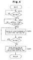
generating a start signal indicating that the engine (11) is being started; and
transferring the driving force of the engine (11) to the auxiliary heating system (21,22) only when a predetermined time period has passed after the start signal is generated. - The method according to claim 1,
characterized in that
the auxiliary heating system includes a viscous heater (22) for generating heat by agitating a viscous fluid. - An auxiliary heating control apparatus for a vehicle, the vehicle having an engine (11), an engine cooling system (14) for heating coolant, a passenger compartment (13,131,132), a main heating system (16) for heating the passenger compartment (13,131,132) using heat from the coolant, and an auxiliary heating system (22), wherein the auxiliary heating system (22) uses the driving force of the engine (11) to heat the coolant separately from the engine cooling system (14,15), the apparatus comprising:wherein the judging means (40) includes a speed detector for detecting the rotational speed of the engine;torque transfer means (35) for transferring the driving force of the engine (11) to a heat generating means (22), wherein the torque transfer means (35) has an engaged state where the driving force of the engine is transferred to the heat generating means (22) and a disengaged state where the heat generating means is not operated;means (40) for judging whether the engine has reached a predetermined running condition,
control means (24) for switching the torque transfer means between the engaged state and the disengaged state,
wherein the control means switches the torque transfer means (35) to the engaged state only when the judging means (40) judges that the engine (11) has reached the predetermined running condition;
characterized in that
the control means switches the torque transfer means (35) to the engaged state earliest when the engine reaches a predetermined rotational speed. - The apparatus according to claim 4,
characterized in that
the control means (24) engages the torque transfer means (35) only after a predetermined time period has elapsed from when the engine (11) reaches the predetermined rotational speed. - The apparatus according to claim 4,
characterized by
means (42) for generating a start signal indicating that the engine (11) is being started, wherein the control means (24) engages the torque transfer means (35) only when a predetermined time period has passed after the start signal is generated. - The apparatus according to claim 4,
characterized in that
the torque transfer means is an electromagnetic clutch (35). - The apparatus according to claim 4,
characterized in that
the auxiliary heating system includes a viscous heater (22) for generating heat by agitating a viscous fluid. - The apparatus according to claim 8,
characterized in that
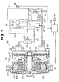
the viscous heater (22) further comprises:a heat generating chamber (29) for accommodating a viscous fluid and a rotor element (33);a heat receiving chamber (30) for receiving heat from the heat generating chamber (29) and for accommodating circulating cooling fluid; anda housing (25, 26) for housing the heat generating chamber (29) and an heat receiving chamber (30).
Applications Claiming Priority (3)
| Application Number | Priority Date | Filing Date | Title |
|---|---|---|---|
| JP08540696A JP3215795B2 (en) | 1996-04-08 | 1996-04-08 | Operation control method and device for auxiliary heating device in vehicle |
| JP8540696 | 1996-04-08 | ||
| JP85406/96 | 1996-04-08 |
Publications (3)
| Publication Number | Publication Date |
|---|---|
| EP0800941A2 EP0800941A2 (en) | 1997-10-15 |
| EP0800941A3 EP0800941A3 (en) | 1999-06-09 |
| EP0800941B1 true EP0800941B1 (en) | 2003-07-02 |
Family
ID=13857924
Family Applications (1)
| Application Number | Title | Priority Date | Filing Date |
|---|---|---|---|
| EP97105689A Expired - Lifetime EP0800941B1 (en) | 1996-04-08 | 1997-04-07 | Method and apparatus for controlling operation of auxiliary heating system of vehicle |
Country Status (7)
| Country | Link |
|---|---|
| US (1) | US5829675A (en) |
| EP (1) | EP0800941B1 (en) |
| JP (1) | JP3215795B2 (en) |
| KR (1) | KR100203005B1 (en) |
| CN (1) | CN1103703C (en) |
| CA (1) | CA2202022C (en) |
| DE (1) | DE69723142T2 (en) |
Families Citing this family (10)
| Publication number | Priority date | Publication date | Assignee | Title |
|---|---|---|---|---|
| KR20030088982A (en) * | 2002-05-15 | 2003-11-21 | 기아자동차주식회사 | Auxiliary Heater For An Automoile Heating System |
| CN100473555C (en) * | 2004-02-26 | 2009-04-01 | 万泰克有限公司 | Vehicle supplemental heating system |
| US7735744B2 (en) * | 2004-03-11 | 2010-06-15 | Nissan Technical Center North America, Inc. | Control of coolant flow rate for vehicle heating |
| DE102004034243A1 (en) * | 2004-07-15 | 2006-02-09 | Webasto Ag | Heating system for motor vehicle has activation delay unit which activates at least one component of heating system via vehicle operating parameter if there adequate likelihood that vehicle will not just be running for short period |
| JP4459046B2 (en) * | 2004-12-27 | 2010-04-28 | トヨタ自動車株式会社 | Automobile and control method thereof |
| US8480006B2 (en) * | 2006-09-08 | 2013-07-09 | Ventech, Llc | Vehicle supplemental heating system |
| US7686146B2 (en) * | 2006-09-27 | 2010-03-30 | Denso International America, Inc. | Combination viscous fan drive and viscous heat device |
| US9228760B2 (en) * | 2012-04-27 | 2016-01-05 | Mac, Inc. | Flameless heating system |
| US9682608B2 (en) * | 2013-01-30 | 2017-06-20 | Hanon Systems | Supplemental heating and cooling sources for a heating, ventilation and air conditioning system |
| US9995508B2 (en) * | 2014-11-18 | 2018-06-12 | Multitek North America, Llc | Systems for heating water used in hydraulic fracturing |
Family Cites Families (12)
| Publication number | Priority date | Publication date | Assignee | Title |
|---|---|---|---|---|
| DE3231903A1 (en) * | 1982-08-27 | 1984-03-01 | Robert Bosch Gmbh, 7000 Stuttgart | Heating device |
| JPS60113722A (en) * | 1983-11-26 | 1985-06-20 | Mazda Motor Corp | Warming apparatus |
| JPS60138822A (en) * | 1983-12-27 | 1985-07-23 | Hitachi Ltd | Impregnated cathode |
| JPS6130884A (en) * | 1984-07-23 | 1986-02-13 | Matsushita Electric Ind Co Ltd | Cylinder for segment type vtr |
| FR2585635B1 (en) * | 1985-07-30 | 1987-11-13 | Valeo | HEAT GENERATOR FOR MOTOR VEHICLE |
| FR2593750B1 (en) * | 1986-02-03 | 1989-10-27 | Valeo | FRICTION HEAT GENERATOR, ESPECIALLY FOR A MOTOR VEHICLE |
| JP2712510B2 (en) * | 1989-03-21 | 1998-02-16 | アイシン精機株式会社 | Vehicle heating system |
| JP2712516B2 (en) * | 1989-03-28 | 1998-02-16 | アイシン精機株式会社 | Vehicle heating system |
| JPH07115581B2 (en) * | 1989-07-25 | 1995-12-13 | アイシン精機株式会社 | Vehicle heating system |
| US5063513A (en) * | 1990-06-15 | 1991-11-05 | Nartron Corporation | Vehicle preheater control |
| JP3116589B2 (en) * | 1992-09-16 | 2000-12-11 | 株式会社デンソー | Vehicle heating system |
| DE4420841A1 (en) * | 1994-06-15 | 1995-12-21 | Hans Dipl Ing Martin | Motor vehicle heater |
-
1996
- 1996-04-08 JP JP08540696A patent/JP3215795B2/en not_active Expired - Fee Related
-
1997
- 1997-04-07 CA CA002202022A patent/CA2202022C/en not_active Expired - Fee Related
- 1997-04-07 EP EP97105689A patent/EP0800941B1/en not_active Expired - Lifetime
- 1997-04-07 KR KR1019970012720A patent/KR100203005B1/en not_active IP Right Cessation
- 1997-04-07 US US08/835,311 patent/US5829675A/en not_active Expired - Fee Related
- 1997-04-07 DE DE69723142T patent/DE69723142T2/en not_active Expired - Fee Related
- 1997-04-07 CN CN97113405A patent/CN1103703C/en not_active Expired - Fee Related
Also Published As
| Publication number | Publication date |
|---|---|
| EP0800941A2 (en) | 1997-10-15 |
| DE69723142D1 (en) | 2003-08-07 |
| KR100203005B1 (en) | 1999-06-15 |
| EP0800941A3 (en) | 1999-06-09 |
| CA2202022A1 (en) | 1997-10-08 |
| DE69723142T2 (en) | 2004-05-27 |
| JPH09272326A (en) | 1997-10-21 |
| CA2202022C (en) | 2000-09-26 |
| JP3215795B2 (en) | 2001-10-09 |
| CN1103703C (en) | 2003-03-26 |
| KR970069442A (en) | 1997-11-07 |
| US5829675A (en) | 1998-11-03 |
| CN1174787A (en) | 1998-03-04 |
Similar Documents
| Publication | Publication Date | Title |
|---|---|---|
| EP0800941B1 (en) | Method and apparatus for controlling operation of auxiliary heating system of vehicle | |
| JP4078742B2 (en) | Vehicle heating system | |
| US20080115745A1 (en) | Engine cooling system for vehicle | |
| JPS60113017A (en) | Operation control method for cooling fan of 2-system cooling type internal-combustion engine | |
| EP1000787B1 (en) | Vehicle refrigerating cycle apparatus and method for inhibiting cycle corrosion and for facilitating rapid passenger compartment warm-up during low temperature conditions | |
| US5906177A (en) | Vehicle heating system | |
| JP3116589B2 (en) | Vehicle heating system | |
| EP1101915B1 (en) | Cooling system and method of internal combustion engine | |
| JP2004360509A (en) | Cooling system for internal combustion engine | |
| EP0993975A1 (en) | A system and method for regulating coolant flow rate to a heat exchanger | |
| EP0573658A1 (en) | Method of demagnetization prevention and control for electric motor | |
| JP2007186089A (en) | Warming-up device for vehicular equipment | |
| JPH1178494A (en) | Heating device for automobile | |
| JP3175734B2 (en) | Vehicle heating system | |
| JPH10203142A (en) | Heating device for vehicle | |
| JP2000108642A (en) | Heating system for vehicle and its control method | |
| JPH10175419A (en) | Heating system for vehicle | |
| JP2000186551A (en) | Cooling fan control device | |
| JPH09315133A (en) | Vehicular heater | |
| JPH11263117A (en) | Auxiliary heater device for vehicle | |
| KR19980053078A (en) | Automotive Radiator Cooling Fan Control | |
| JP4103241B2 (en) | Air conditioner for vehicles | |
| JPH0941971A (en) | Control unit of radiator fan driving motor | |
| KR20000032589A (en) | Magnetic pulley of water pump for vehicle | |
| US5908010A (en) | Viscous fluid heater |
Legal Events
| Date | Code | Title | Description |
|---|---|---|---|
| PUAI | Public reference made under article 153(3) epc to a published international application that has entered the european phase |
Free format text: ORIGINAL CODE: 0009012 |
|
| 17P | Request for examination filed |
Effective date: 19970407 |
|
| AK | Designated contracting states |
Kind code of ref document: A2 Designated state(s): DE FR GB SE |
|
| PUAL | Search report despatched |
Free format text: ORIGINAL CODE: 0009013 |
|
| AK | Designated contracting states |
Kind code of ref document: A3 Designated state(s): DE FR GB SE |
|
| RAP1 | Party data changed (applicant data changed or rights of an application transferred) |
Owner name: DENSO CORPORATION Owner name: TOYOTA JIDOSHA KABUSHIKI KAISHA Owner name: KABUSHIKI KAISHA TOYOTA JIDOSHOKKI |
|
| 17Q | First examination report despatched |
Effective date: 20020129 |
|
| GRAH | Despatch of communication of intention to grant a patent |
Free format text: ORIGINAL CODE: EPIDOS IGRA |
|
| GRAH | Despatch of communication of intention to grant a patent |
Free format text: ORIGINAL CODE: EPIDOS IGRA |
|
| GRAA | (expected) grant |
Free format text: ORIGINAL CODE: 0009210 |
|
| AK | Designated contracting states |
Designated state(s): DE FR GB SE |
|
| REG | Reference to a national code |
Ref country code: GB Ref legal event code: FG4D |
|
| REG | Reference to a national code |
Ref country code: SE Ref legal event code: TRGR |
|
| REF | Corresponds to: |
Ref document number: 69723142 Country of ref document: DE Date of ref document: 20030807 Kind code of ref document: P |
|
| ET | Fr: translation filed | ||
| PLBE | No opposition filed within time limit |
Free format text: ORIGINAL CODE: 0009261 |
|
| STAA | Information on the status of an ep patent application or granted ep patent |
Free format text: STATUS: NO OPPOSITION FILED WITHIN TIME LIMIT |
|
| 26N | No opposition filed |
Effective date: 20040405 |
|
| PGFP | Annual fee paid to national office [announced via postgrant information from national office to epo] |
Ref country code: SE Payment date: 20090407 Year of fee payment: 13 Ref country code: FR Payment date: 20090417 Year of fee payment: 13 Ref country code: DE Payment date: 20090402 Year of fee payment: 13 |
|
| PGFP | Annual fee paid to national office [announced via postgrant information from national office to epo] |
Ref country code: GB Payment date: 20090401 Year of fee payment: 13 |
|
| EUG | Se: european patent has lapsed | ||
| GBPC | Gb: european patent ceased through non-payment of renewal fee |
Effective date: 20100407 |
|
| REG | Reference to a national code |
Ref country code: FR Ref legal event code: ST Effective date: 20101230 |
|
| PG25 | Lapsed in a contracting state [announced via postgrant information from national office to epo] |
Ref country code: DE Free format text: LAPSE BECAUSE OF NON-PAYMENT OF DUE FEES Effective date: 20101103 |
|
| PG25 | Lapsed in a contracting state [announced via postgrant information from national office to epo] |
Ref country code: GB Free format text: LAPSE BECAUSE OF NON-PAYMENT OF DUE FEES Effective date: 20100407 |
|
| PG25 | Lapsed in a contracting state [announced via postgrant information from national office to epo] |
Ref country code: FR Free format text: LAPSE BECAUSE OF NON-PAYMENT OF DUE FEES Effective date: 20100430 |
|
| PG25 | Lapsed in a contracting state [announced via postgrant information from national office to epo] |
Ref country code: SE Free format text: LAPSE BECAUSE OF NON-PAYMENT OF DUE FEES Effective date: 20100408 |