EP0800865B1 - Poste de travail de laboratoire - Google Patents
Poste de travail de laboratoire Download PDFInfo
- Publication number
- EP0800865B1 EP0800865B1 EP97105781A EP97105781A EP0800865B1 EP 0800865 B1 EP0800865 B1 EP 0800865B1 EP 97105781 A EP97105781 A EP 97105781A EP 97105781 A EP97105781 A EP 97105781A EP 0800865 B1 EP0800865 B1 EP 0800865B1
- Authority
- EP
- European Patent Office
- Prior art keywords
- modules
- work station
- laboratory work
- station according
- module
- Prior art date
- Legal status (The legal status is an assumption and is not a legal conclusion. Google has not performed a legal analysis and makes no representation as to the accuracy of the status listed.)
- Expired - Lifetime
Links
- 239000011521 glass Substances 0.000 claims description 9
- 238000009434 installation Methods 0.000 description 6
- 238000010276 construction Methods 0.000 description 5
- 230000008901 benefit Effects 0.000 description 4
- 238000006243 chemical reaction Methods 0.000 description 4
- 230000008878 coupling Effects 0.000 description 4
- 238000010168 coupling process Methods 0.000 description 4
- 238000005859 coupling reaction Methods 0.000 description 4
- 238000009420 retrofitting Methods 0.000 description 4
- 239000000463 material Substances 0.000 description 3
- 230000008859 change Effects 0.000 description 2
- 238000000926 separation method Methods 0.000 description 2
- 241001136792 Alle Species 0.000 description 1
- 229910000831 Steel Inorganic materials 0.000 description 1
- 230000006978 adaptation Effects 0.000 description 1
- 239000000919 ceramic Substances 0.000 description 1
- 230000036461 convulsion Effects 0.000 description 1
- 230000000694 effects Effects 0.000 description 1
- 238000005246 galvanizing Methods 0.000 description 1
- 238000007726 management method Methods 0.000 description 1
- 238000012986 modification Methods 0.000 description 1
- 230000004048 modification Effects 0.000 description 1
- 238000010079 rubber tapping Methods 0.000 description 1
- 239000010959 steel Substances 0.000 description 1
- 239000000126 substance Substances 0.000 description 1
- 239000002351 wastewater Substances 0.000 description 1
Images


Classifications
-
- A—HUMAN NECESSITIES
- A47—FURNITURE; DOMESTIC ARTICLES OR APPLIANCES; COFFEE MILLS; SPICE MILLS; SUCTION CLEANERS IN GENERAL
- A47B—TABLES; DESKS; OFFICE FURNITURE; CABINETS; DRAWERS; GENERAL DETAILS OF FURNITURE
- A47B96/00—Details of cabinets, racks or shelf units not covered by a single one of groups A47B43/00 - A47B95/00; General details of furniture
- A47B96/06—Brackets or similar supporting means for cabinets, racks or shelves
- A47B96/067—Horizontal rails as suspension means in a cantilever arrangement
-
- B—PERFORMING OPERATIONS; TRANSPORTING
- B01—PHYSICAL OR CHEMICAL PROCESSES OR APPARATUS IN GENERAL
- B01L—CHEMICAL OR PHYSICAL LABORATORY APPARATUS FOR GENERAL USE
- B01L9/00—Supporting devices; Holding devices
- B01L9/02—Laboratory benches or tables; Fittings therefor
-
- F—MECHANICAL ENGINEERING; LIGHTING; HEATING; WEAPONS; BLASTING
- F16—ENGINEERING ELEMENTS AND UNITS; GENERAL MEASURES FOR PRODUCING AND MAINTAINING EFFECTIVE FUNCTIONING OF MACHINES OR INSTALLATIONS; THERMAL INSULATION IN GENERAL
- F16B—DEVICES FOR FASTENING OR SECURING CONSTRUCTIONAL ELEMENTS OR MACHINE PARTS TOGETHER, e.g. NAILS, BOLTS, CIRCLIPS, CLAMPS, CLIPS OR WEDGES; JOINTS OR JOINTING
- F16B12/00—Jointing of furniture or the like, e.g. hidden from exterior
- F16B12/10—Jointing of furniture or the like, e.g. hidden from exterior using pegs, bolts, tenons, clamps, clips, or the like
- F16B12/28—Jointing of furniture or the like, e.g. hidden from exterior using pegs, bolts, tenons, clamps, clips, or the like for metal furniture parts
- F16B12/38—Jointing of furniture or the like, e.g. hidden from exterior using pegs, bolts, tenons, clamps, clips, or the like for metal furniture parts using snap-action elements
Definitions
- the invention relates to a laboratory workstation with at least an energy cell with a provided media supply and internals and one in front of the energy cell Work table, the energy cell consisting of two vertical stands is built up by at least two cross beams with each other are connected and the internals in the form of a set of interchangeable modules with different functions that are above the workbench height Brackets are attached.
- a laboratory workplace is known from EP-A-0486789.
- the top of the table top is arranged and has several cross members, which are vertically spaced, internals directly on the cross beams to install.
- Laboratory workplaces are for work in laboratories of all Kind, especially in schools, colleges, institutes and companies intended. You need in addition to the work surfaces and storage space a number of different types of media supplies as well further storage areas.
- Laboratory buildings are complex structures because of their Complexity requires long planning and construction times. In particular in public buildings are often those in building planning intended users and the actual users at Indent different. They also change in research the work content constantly, which means that a laboratory is due the long planning time when moving in often no longer meets the requirements enough. But because of the usual laboratory workstation systems later changes hardly possible or with high costs are usually charged by users very high demands on the possible uses, thus also activities and work only started later can be executed without significant changes being necessary are. These requirements particularly concern media assembly, the chemical resistance and the storage space. This in turn has the consequence that laboratories in their Acquisition very expensive and usually around 100%, especially in the Media assembly, are oversized.
- Laboratory workplaces are usually linear parallel to arranged on the outer walls of a laboratory room.
- a standard workplace The type mentioned at the beginning comprises an energy cell with the provided media supplies.
- the energy cell consists of two vertical stands connected with cross members are. The permanently installed are in the lower area Passage lines for the media, which have multiple workplaces connect with each other.
- At an altitude of around 900 to A media bar is provided at 1200 mm, in the linear next to each other Media fittings are attached.
- the media fittings are screwed into the media bar from the front and above the media bar is located across the entire width of the energy cell an electrical channel in which electrical withdrawals and fuses are installed.
- the Energy cell is a work table, for example from a Steel frame or a supporting substructure on which a table top is arranged.
- Another laboratory workstation system is known from EP-A-0 486 789 known, that of perforated vertical stands and perforated Truss is built. The through lines are driven inside outbreaks of the stand and the vertical Stub and access lines run inside the perforated Traverses.
- This laboratory workstation system is in endless construction built up so that there is only one stand element at each joint located. With this system, the work tables are still in the stand elements hooked in, so that the stand as a load-bearing Parts of the work tables work.
- the ELT assembly is located in electrical modules, the sanitary removal in sanitary modules, these modules being approximately 600 by 300 mm in size to have. Trays are attached to cross tubes in front of the stands run. It is also proposed that the stand elements simultaneously represent the laboratory walls.
- the object underlying the invention is in contrast in the laboratory workplace of the type mentioned at the beginning to be trained so that he has a high flexibility for retrofitting, adaptation etc. during the planning, construction and use phase Has.
- brackets are provided on the cross beams of the energy cell are and consist of clamping profiles that are in one piece with the Cross beams are formed.
- a laboratory work station essentially consists of one Energy cell and a work table in front of it.
- the work table carries a countertop on which, for example Trials are running.
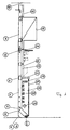
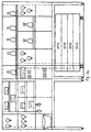
- the energy cell is off a support chassis to which modules are attached can.
- the carrying chassis consists of two vertical stands or stand profiles 1, which have holes or grid holes on their inside 3 for attaching cross beams of all kinds.
- a Stand foot 2 At the lower end of the stand profiles 1 is a Stand foot 2, the leveling device 4 bumps balances.
- the stand profiles 1 do not go up to to the floor but leave a gap 5 to the floor so that the Stand profiles 1 are arranged independently of the floor tiles 6 can be.
- the stand profiles are 1 above the tabletop height connected to cross members 7, the height of the grid holes 3 adjustable are attached.
- the stand profiles 1 can if necessary by means of a stand extension 9 from another Stand profile can be extended to the ceiling. Then you can be attached to the ceiling by means of a ceiling anchor 10.
- a console 11 On the height of the worktop, i.e. at an altitude of 720 or 900 mm there is a console 11.
- the space between the Stand foot and the console 11 is the installation space 18 for horizontal supply lines.
- the ELT feed-through lines 19 In the upper part of this room are the ELT feed-through lines 19, below are the Sanitary lines 20. Sniffer lines and Waste water pipes 21 can be guided in this room.
- At least two cross members 7 are located above the bracket 11 provided on which at least one horizontal row of modules 12 can be attached.
- the modules 12 can reach the ceiling pass.
- wall cabinets 15 or panels 16 to attach to the cross members 7, wherein when the facing 16 is soundproof, the energy cell can also serve as a room divider or room divider can.
- the cross members 7 provided with vertical recesses 22 through which at high Stability of the cross member 7 vertical lines are guided can. These lines can be branch lines to fittings or Access lines from the ceiling to the energy cell.
- modules 12 can be attached to the cross member 7.
- the modules 12 have a depth of approximately 25 mm.
- the result for the entire Energy cell a clear definition of how the media lines can be managed independently.
- the through lines are guided in the horizontal space 18, the space between the vertical stand profiles 1 is for vertical lines reserved, possibly through the recesses 22 in the cross members 7 are performed.
- room 13 within the modules 12 can if necessary, short cross lines between the modules be laid.
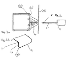
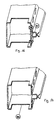
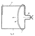
- Fig. 3 (not under claim 1 below) it is shown how the modules 12 on the energy cell, i.e. are attached to the cross member 7 of the energy cell.
- the modules 12 are fastened according to FIG. 3a by means of a clip 25 which has a guide 27 for the modules 12. On this guide 27, the modules 12 are in terms of height and led the deep.
- the modules 12 are also by means of a Snap 26 of the clip attached.
- the locking lug 26 projects through a Recess in the module 12. Pushes through a clip pretension the latch 26 through the module 12 until the module 12 abuts a contact surface 30, with a stop surface 29 Removing the module 12 prevents non-positive.
- a disassembly is possible by means of a dismantling tool 33 (FIG.
- the dismantling tool 33 presses against the contact surface 30 Clip 25 out of module 12. Using an oblique rag 36 of the dismantling tool 33, the module 12 can then be pulled out become. At the end, a deflector slope 31 slides along the wall thickness the module 12 to the outside. If a module 12 is attached can be done with a single clip.
- the Clips can additionally have a dome 37 (FIGS. 7a, 7b). With such clips, modules 12 with a heavy load can additionally be fastened by means of a screw 38, which in the cathedral 37 is screwed.
- Fig. 16 shows an alternative type of attachment for the Modules 12.
- a clamping profile 85 can by means of cage nuts be attached to the cross member 7 of the energy cell (not covered by claim 1).
- the clamping profile is formed on the cross member 7, i.e. Clamp profile and cross member are formed in a profile part 86, which is a very easy to assemble embodiment.
- Fig. 18 shows an embodiment with the cross member molded continuous clamping profiles 85 for clamping and Holding the modules 12, in which spring clips 89 are additionally provided are snapped into the cross section 7 and Increase the clamping or holding force of the clamping profiles 85 in that they squeeze them together Such spring chambers 89 are then used if e.g. a high holding force for fittings is needed.
- the spring clips 89 can be in the form of tension hooks be formed as shown in Fig. 18.
- a module 12 is inserted into a clamping profile 85 snapped in so that it is there provided on the module 12 Latch holds.
- a jerk that causes the latch leaves the springs of the clamping profiles 85, the module could subtracted from. This is done by applying the spring clips 89 prevents the holding force of the clamping profiles 85 so increase that module 12 cannot be easily removed can.
- a tool e.g. a spatula-like Tool pushed from the front through the clamping profile 85 to the rear until they fall into the cutout in cross member 7.
- the modules 12 all have the same main dimensions and the same type of attachment to the cross beams 7. All modules 12 are interchangeable.
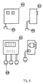
- the modules 12 are provided in the form of a module set, which consists of at least the following individual modules:
- the dummy or empty module 62 is the base unit for the equipped modules.
- the empty module 62 consists of a flat one Area with a rectangular format and is on all four sides canted. The side surfaces have cutouts for cable entries. The top and bottom faces have an or several holes or stampings to the empty module 62 to clip a cross beam 7.
- the removal module 55 has a greater depth than the others However, modules have the same dimensions in height and in the Width.
- a distribution module 56 (see also Fig. 15), in which the on-site supply line 60 contains terminals and fuses for the remaining modules. It also contains at least one Outgoing socket 58.
- the removal modules 55 have at least one 220 V or 380 V socket. All removal modules 55 are included provide a cable with an input connector. The removal modules 55 are thereby supplied by the distribution module 56. With longer ones It is possible to provide extension cables for distances, which are guided in the horizontal installation space while short distances via lines in recesses 63 behind the Modules can be bridged. Can continue Coupling pieces 61 may be provided so that on an outlet socket 58 a branch for connecting a plurality of removal modules 55 can be formed on an outgoing line. That way it is readily possible to locate the removal modules 55 change.
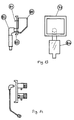
- the sanitary module carries the sanitary, gas and clean gas fittings.
- two rows of fittings can be stacked be set so that on a module with 300 by 300 mm 5 fittings can be positioned.
- the fittings show in 14, an internal thread in the rear area on.
- the connection is made with a connection bracket, which also ensures the downward deflection.
- the connection angle has a long external thread through which the connection to the valve he follows.
- the valve is attached to the module housing with a lock nut pressed and fastened there. By separating between the sanitary connection and the mechanical fastening of the Assembly is greatly facilitated. The previous attachment locking the valve often led to leaks, because the valve could only be turned to the vertical position.
- connection bracket also has a screw connection or connection coupling on which a connection hose is attached.
- this is Hose inserted into a screw connection or coupling. This is located in a T-piece of the through line, which is located in the room. Since all vertical stub lines with hoses are executed, the module 12 can be easily disassembled and be removed from the holding position. Then the hoses disassembled and the module can be positioned elsewhere become. It is also a fitting retrofit possible, and retrofitting of the same media can be done easily, by simply inserting an additional coupling piece into the Branch line is inserted.
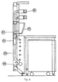
- a pool module carries a drain pool on the module body 80.
- the drain basin 80 is screwed from the inside of the module or glued to the module. That depends on the pool material from. Ceramic basins, for example, have to be glued.
- the pool has a nozzle 83 at the back, which together with a bow 82 with a seal forms a sanitary connection.
- a siphon 84 is connected behind the bend. Subsequently the vertical branch line is connected to the ground line.
- the installation of the pool module in the energy cell has a crucial one Advantage, because it creates a clear separation between the energy cell and the furniture, i.e. achieved the work table is in front of the energy cell. In addition, the pool module be replaced.
- Tripod module (Fig. 10)
- Tripods have so far mostly been used for constructional reasons Connection to the glass shelf provided. However, that poses again a combination of non-interconnected components represents, so the use of a tripod module the better System solution is.
- the tripod holder 67 are from behind a screw 68 attached.
- Shelves are an important component of a laboratory work station.
- Storage holders 70 are, for example, on the storage module Screws 74 attached.
- the storage holder 70 can grid holes 71, on which shelves of different depths can be attached.
- the tray holder 70 can on one Module or attached to adjacent modules, to achieve a wider range.
- the glass shelves are also attached to modules.
- the glass holding profiles 76 are by means of screws 77 over the module with the Cross member 7 screwed.
- the glass shelf modules can be like that Storage modules also extend over several module grids.
- any other components can be attached to the modules become.
- wall cabinet modules Modules with veneers to the ceiling or soundproof modules be provided.
- the modules only have to be in grid and in can be attached in the same way.
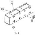
- Fig. 6a two energy cells are shown, above three rows of modules are provided on the work surface of the work table are.
- the bottom row consists of a pool module and then from empty modules.
- the middle row consists of two sanitary modules, one empty module, one sanitary module, two Storage modules and an electrical module.
- the top row is there consisting of a sanitary module, two storage modules and five glass storage modules.
- In front of the unit there is a three module wider Worktable. To the right of this is a veneer that over five modules is enough. For example, there can be a large device stand.
Landscapes
- Engineering & Computer Science (AREA)
- General Engineering & Computer Science (AREA)
- Mechanical Engineering (AREA)
- Chemical Kinetics & Catalysis (AREA)
- Chemical & Material Sciences (AREA)
- Clinical Laboratory Science (AREA)
- Health & Medical Sciences (AREA)
- Devices For Use In Laboratory Experiments (AREA)
- General Preparation And Processing Of Foods (AREA)
- Filters For Electric Vacuum Cleaners (AREA)
- Glass Compositions (AREA)
- Insulated Conductors (AREA)
- Apparatus Associated With Microorganisms And Enzymes (AREA)
Claims (11)
- Poste de travail de laboratoire comprenant au moins une cellule d'énergie pourvue d'une alimentation en fluides et de composants intégrés, et une table de travail agencée devant la cellule d'énergie, la cellule d'énergie étant formée par deux montants verticaux qui sont assemblés entre eux par au moins deux traverses, et les composants intégrés étant prévus sous la forme d'un jeu de modules amovibles avec différentes fonctionnalités, qui sont agencés avec des fixations au-dessus du niveau de la table de travail, caractérisé en ce que les fixations sont prévues au niveau des traverses de la cellule d'énergie et sont formées par des profilés de blocage, qui sont conçus d'une seule pièce avec les traverses.
- Poste de travail de laboratoire selon la revendication 1, caractérisé en ce que plusieurs cellules d'énergie et les modules sont disposés côte à côte et/ou les uns derrière les autres selon un motif déterminé.
- Poste de travail de laboratoire selon la revendication 1, caractérisé par des pinces à ressort, qui sont insérées dans les traverses et qui compriment les profilés de blocage.
- Poste de travail de laboratoire selon la revendication 3, caractérisé en ce qu'il est possible de faire coulisser les pinces à ressort à partir de la face avant des profilés de blocage vers l'arrière.
- Poste de travail de laboratoire selon l'une quelconque des revendications précédentes, caractérisé en ce que parmi les modules sont prévus des modules de fusibles électriques et des modules de distribution électrique, qui peuvent être reliés les uns aux autres par l'intermédiaire de connecteurs.
- Poste de travail de laboratoire selon l'une quelconque des revendications précédentes, caractérisé en ce que parmi les modules sont prévus des modules sanitaires, qui sont munis de robinets, fixés sur la face arrière des modules sanitaires, les raccords d'acheminement des fluides étant indépendants de la fixation mécanique des modules.
- Poste de travail de laboratoire selon l'une quelconque des revendications précédentes, caractérisé en ce que les modules pour les raccords d'acheminement des fluides sont assemblés par l'intermédiaire de tuyaux flexibles avec les systèmes d'alimentation en fluides de la cellule d'énergie.
- Poste de travail de laboratoire selon l'une quelconque des revendications précédentes, caractérisé en ce que parmi les modules sont prévus des modules d'évacuation, au niveau desquels sont fixées des cuvettes d'évacuation, qui peuvent être retirées par l'avant.
- Poste de travail de laboratoire selon l'une quelconque des revendications précédentes, caractérisé en ce que parmi les modules sont prévus des modules de réception, qui ont un pas de motif simple ou multiple.
- Poste de travail de laboratoire selon l'une quelconque des revendications précédentes, caractérisé en ce que parmi les modules sont des modules de réception en verre, qui ont un pas de motif simple ou multiple.
- Poste de travail de laboratoire selon l'une quelconque des revendications précédentes, caractérisé en ce que les montants verticaux de la cellule d'énergie ne descendent pas jusqu'au niveau du sol.
Applications Claiming Priority (2)
| Application Number | Priority Date | Filing Date | Title |
|---|---|---|---|
| DE19614370 | 1996-04-11 | ||
| DE19614370A DE19614370C1 (de) | 1996-04-11 | 1996-04-11 | Laborarbeitsplatz |
Publications (3)
| Publication Number | Publication Date |
|---|---|
| EP0800865A2 EP0800865A2 (fr) | 1997-10-15 |
| EP0800865A3 EP0800865A3 (fr) | 1998-08-26 |
| EP0800865B1 true EP0800865B1 (fr) | 2003-01-22 |
Family
ID=7791019
Family Applications (1)
| Application Number | Title | Priority Date | Filing Date |
|---|---|---|---|
| EP97105781A Expired - Lifetime EP0800865B1 (fr) | 1996-04-11 | 1997-04-08 | Poste de travail de laboratoire |
Country Status (4)
| Country | Link |
|---|---|
| EP (1) | EP0800865B1 (fr) |
| AT (1) | ATE231414T1 (fr) |
| DE (2) | DE19614370C1 (fr) |
| ES (1) | ES2188812T3 (fr) |
Families Citing this family (13)
| Publication number | Priority date | Publication date | Assignee | Title |
|---|---|---|---|---|
| ES2134719B1 (es) * | 1997-04-25 | 2000-05-01 | Munoz Julian Romero | Mesa de laboratorio perfeccionada. |
| DE69925699T2 (de) | 1998-12-25 | 2006-03-23 | Tosoh Corp., Shinnanyo | Verbrennungskatalysatoren und Verfahren zur Entfernung von organischen Verbindungen |
| ES2177355B1 (es) * | 1999-02-17 | 2004-11-16 | Burdinola, S. Coop. | Sistema estructural modular para conducciones de fluidos tanto en mobiliario como en instalaciones de laboratorio o similares. |
| FR2791233B1 (fr) * | 1999-03-24 | 2003-03-21 | Burdinola S Coop | Structure modulaire pour conduites de fluides dans le mobilier et les installations de laboratoire ou similaire |
| DE10154128B4 (de) * | 2001-10-25 | 2009-09-03 | Hermann Schaffitzel | Medienzelle für ein Labor oder dergleichen |
| ES2208046B1 (es) * | 2002-01-10 | 2005-04-01 | Julian Romero Muñoz | Sistema modular de instalaciones de mesas de laboratorio. |
| ES2234374B1 (es) * | 2002-11-12 | 2006-05-16 | Julian Romero Muñoz | Sistema constructivo para mueble-estanteria de laboratorio. |
| DE102006055000B4 (de) * | 2005-12-15 | 2007-09-20 | GfP (Gesellschaft für Produktivitätsplanung und Produktentwicklung) mbH | Vorrichtung zum Bereitstellen und/oder zur Bevorratung und/oder zur Erzeugung wenigstens eines Mediums an einem Arbeitstisch, sowie Baugruppe zur Verbindung mit dem Arbeitstisch und System für unterschiedliche Medien |
| DE202008016891U1 (de) * | 2008-12-19 | 2010-05-12 | VS Vereinigte Spezialmöbelfabriken GmbH & Co. KG | Laborarbeitsplatz |
| DE102009002454A1 (de) | 2009-04-17 | 2010-10-28 | Waldner Laboreinrichtungen Gmbh & Co. Kg | Medienkanal für eine Laboreinrichtung |
| DE102009020726A1 (de) * | 2009-05-11 | 2010-11-25 | Wesemann Gmbh & Co. Kg | Versorgungssystem zum Bereitstellen einer Medienversorgung |
| EP3240129B1 (fr) | 2016-04-27 | 2023-12-20 | arc2lab GmbH | Système d'alimentation |
| DE102017105852A1 (de) * | 2017-03-17 | 2018-09-20 | Wesemann Gmbh | Medienversorgungssystem |
Family Cites Families (5)
| Publication number | Priority date | Publication date | Assignee | Title |
|---|---|---|---|---|
| FR2411633A1 (fr) * | 1977-12-16 | 1979-07-13 | Alsthom Atlantique | Dispositif de support pour equipement de salles de laboratoire et de fabrication |
| US4320935A (en) * | 1979-10-22 | 1982-03-23 | Herman Miller, Inc. | Structural support system with load control |
| US4544214A (en) * | 1982-12-15 | 1985-10-01 | Architectural Resources Cambridge, Inc. | Laboratory furniture system |
| IT1244081B (it) * | 1990-11-21 | 1994-07-05 | Arredi Tecnici Villa Spa | Sistema modulare per la realizzazione di pareti attrezzate e banchi dilavoro in particolare per laboratori. |
| DE9316330U1 (de) * | 1993-10-26 | 1994-01-13 | Erfi Ernst Fischer Gmbh & Co | Aufbau für Labor- oder Arbeitstische |
-
1996
- 1996-04-11 DE DE19614370A patent/DE19614370C1/de not_active Expired - Fee Related
-
1997
- 1997-04-08 ES ES97105781T patent/ES2188812T3/es not_active Expired - Lifetime
- 1997-04-08 EP EP97105781A patent/EP0800865B1/fr not_active Expired - Lifetime
- 1997-04-08 AT AT97105781T patent/ATE231414T1/de active
- 1997-04-08 DE DE59709170T patent/DE59709170D1/de not_active Expired - Lifetime
Also Published As
| Publication number | Publication date |
|---|---|
| EP0800865A3 (fr) | 1998-08-26 |
| DE19614370C1 (de) | 1997-12-18 |
| EP0800865A2 (fr) | 1997-10-15 |
| ATE231414T1 (de) | 2003-02-15 |
| ES2188812T3 (es) | 2003-07-01 |
| DE59709170D1 (de) | 2003-02-27 |
Similar Documents
| Publication | Publication Date | Title |
|---|---|---|
| EP0800865B1 (fr) | Poste de travail de laboratoire | |
| EP0307620B1 (fr) | Table de travail | |
| EP0398014B1 (fr) | Système d'ameublement variable pour atelier | |
| WO2010119134A2 (fr) | Canal d'énergie pour une installation de laboratoire | |
| WO2001096684A1 (fr) | Paroi fonctionnelle a construction modulaire | |
| DE19615759C2 (de) | Schaltschrank mit Sockel und Rahmengestell | |
| DE10154128B4 (de) | Medienzelle für ein Labor oder dergleichen | |
| DE1778336A1 (de) | System fuer den Zusammenbau von Kastenmoebeln,insbesondere fuer Kuechenmoebel | |
| EP0517938B1 (fr) | Système modulaire de construction | |
| DE3007229A1 (de) | Kabelverteiler | |
| DE60315580T2 (de) | Labormöbel-Konstruktionssystem | |
| EP1123021A2 (fr) | Systeme mobilier variable pour poste de travail, a montants verticaux et entretoises transversales horizontales | |
| DE1591623B1 (de) | Schrank fuer Geraete der Nachrichtentechnik | |
| DE3231802A1 (de) | Arbeitstisch, insbesondere fuer bueroarbeiten | |
| DE19956951C2 (de) | Arbeitsplatzmöbel mit einem Möbelgestell aus vertikalen Säulen und Quertraversen | |
| DE7037254U (de) | Gestellrahmen | |
| DE3740778A1 (de) | Arbeitsplatztisch | |
| DE19615447A1 (de) | Wandsystem insbesondere für Messestände | |
| DE102021131228A1 (de) | Mediensäule für eine Anordnung zur Verteilung von Medien wie gasförmigen und flüssigen Medien, Vacuum, Strom und Kommunikation, in einem Labor | |
| DE102021104139A1 (de) | Medienversorgungssystem | |
| DE2750517C3 (de) | Flächenkabelträger zum Einsatz insbesondere in Telephonzentralen und Verstärkerstellen (TZV) | |
| DE2804016A1 (de) | Labortisch | |
| DE19507725A1 (de) | Schaltschrank mit Rahmengestell und Montageplatten | |
| DE4207282A1 (de) | Laborgestell | |
| CH701250A1 (de) | Vorrichtung für die Medien- und Energieversorgung. |
Legal Events
| Date | Code | Title | Description |
|---|---|---|---|
| PUAI | Public reference made under article 153(3) epc to a published international application that has entered the european phase |
Free format text: ORIGINAL CODE: 0009012 |
|
| AK | Designated contracting states |
Kind code of ref document: A2 Designated state(s): AT CH DE ES FR GB LI |
|
| PUAL | Search report despatched |
Free format text: ORIGINAL CODE: 0009013 |
|
| AK | Designated contracting states |
Kind code of ref document: A3 Designated state(s): AT CH DE ES FR GB LI |
|
| 17P | Request for examination filed |
Effective date: 19981230 |
|
| 17Q | First examination report despatched |
Effective date: 20010730 |
|
| GRAG | Despatch of communication of intention to grant |
Free format text: ORIGINAL CODE: EPIDOS AGRA |
|
| GRAG | Despatch of communication of intention to grant |
Free format text: ORIGINAL CODE: EPIDOS AGRA |
|
| GRAH | Despatch of communication of intention to grant a patent |
Free format text: ORIGINAL CODE: EPIDOS IGRA |
|
| GRAH | Despatch of communication of intention to grant a patent |
Free format text: ORIGINAL CODE: EPIDOS IGRA |
|
| GRAA | (expected) grant |
Free format text: ORIGINAL CODE: 0009210 |
|
| AK | Designated contracting states |
Kind code of ref document: B1 Designated state(s): AT CH DE ES FR GB LI |
|
| REG | Reference to a national code |
Ref country code: GB Ref legal event code: FG4D Free format text: NOT ENGLISH |
|
| REG | Reference to a national code |
Ref country code: CH Ref legal event code: NV Representative=s name: NOVAGRAAF INTERNATIONAL SA Ref country code: CH Ref legal event code: EP |
|
| REF | Corresponds to: |
Ref document number: 59709170 Country of ref document: DE Date of ref document: 20030227 Kind code of ref document: P |
|
| GBT | Gb: translation of ep patent filed (gb section 77(6)(a)/1977) |
Effective date: 20030515 |
|
| REG | Reference to a national code |
Ref country code: ES Ref legal event code: FG2A Ref document number: 2188812 Country of ref document: ES Kind code of ref document: T3 |
|
| ET | Fr: translation filed | ||
| PLBE | No opposition filed within time limit |
Free format text: ORIGINAL CODE: 0009261 |
|
| STAA | Information on the status of an ep patent application or granted ep patent |
Free format text: STATUS: NO OPPOSITION FILED WITHIN TIME LIMIT |
|
| 26N | No opposition filed |
Effective date: 20031023 |
|
| REG | Reference to a national code |
Ref country code: CH Ref legal event code: PFA Owner name: WALDNER LABOREINRICHTUNGEN GMBH & CO. Free format text: WALDNER LABOREINRICHTUNGEN GMBH & CO.#IM WEISSEN BILD 23#88239 WANGEN/ALLGAEU (DE) -TRANSFER TO- WALDNER LABOREINRICHTUNGEN GMBH & CO.#IM WEISSEN BILD 23#88239 WANGEN/ALLGAEU (DE) |
|
| REG | Reference to a national code |
Ref country code: DE Ref legal event code: R082 Ref document number: 59709170 Country of ref document: DE Representative=s name: KOTITSCHKE & HEURUNG PARTNERSCHAFT MBB PATENT-, DE |
|
| REG | Reference to a national code |
Ref country code: FR Ref legal event code: PLFP Year of fee payment: 20 |
|
| PGFP | Annual fee paid to national office [announced via postgrant information from national office to epo] |
Ref country code: GB Payment date: 20160421 Year of fee payment: 20 Ref country code: CH Payment date: 20160420 Year of fee payment: 20 Ref country code: ES Payment date: 20160413 Year of fee payment: 20 Ref country code: DE Payment date: 20160428 Year of fee payment: 20 |
|
| PGFP | Annual fee paid to national office [announced via postgrant information from national office to epo] |
Ref country code: AT Payment date: 20160421 Year of fee payment: 20 Ref country code: FR Payment date: 20160421 Year of fee payment: 20 |
|
| REG | Reference to a national code |
Ref country code: DE Ref legal event code: R071 Ref document number: 59709170 Country of ref document: DE |
|
| REG | Reference to a national code |
Ref country code: CH Ref legal event code: PL |
|
| REG | Reference to a national code |
Ref country code: GB Ref legal event code: PE20 Expiry date: 20170407 |
|
| REG | Reference to a national code |
Ref country code: AT Ref legal event code: MK07 Ref document number: 231414 Country of ref document: AT Kind code of ref document: T Effective date: 20170408 |
|
| PG25 | Lapsed in a contracting state [announced via postgrant information from national office to epo] |
Ref country code: GB Free format text: LAPSE BECAUSE OF EXPIRATION OF PROTECTION Effective date: 20170407 |
|
| REG | Reference to a national code |
Ref country code: ES Ref legal event code: FD2A Effective date: 20180508 |
|
| PG25 | Lapsed in a contracting state [announced via postgrant information from national office to epo] |
Ref country code: ES Free format text: LAPSE BECAUSE OF EXPIRATION OF PROTECTION Effective date: 20170409 |