EP0800865B1 - Laboratory work station - Google Patents
Laboratory work station Download PDFInfo
- Publication number
- EP0800865B1 EP0800865B1 EP97105781A EP97105781A EP0800865B1 EP 0800865 B1 EP0800865 B1 EP 0800865B1 EP 97105781 A EP97105781 A EP 97105781A EP 97105781 A EP97105781 A EP 97105781A EP 0800865 B1 EP0800865 B1 EP 0800865B1
- Authority
- EP
- European Patent Office
- Prior art keywords
- modules
- work station
- laboratory work
- station according
- module
- Prior art date
- Legal status (The legal status is an assumption and is not a legal conclusion. Google has not performed a legal analysis and makes no representation as to the accuracy of the status listed.)
- Expired - Lifetime
Links
- 239000011521 glass Substances 0.000 claims description 9
- 238000009434 installation Methods 0.000 description 6
- 238000010276 construction Methods 0.000 description 5
- 230000008901 benefit Effects 0.000 description 4
- 238000006243 chemical reaction Methods 0.000 description 4
- 230000008878 coupling Effects 0.000 description 4
- 238000010168 coupling process Methods 0.000 description 4
- 238000005859 coupling reaction Methods 0.000 description 4
- 238000009420 retrofitting Methods 0.000 description 4
- 239000000463 material Substances 0.000 description 3
- 230000008859 change Effects 0.000 description 2
- 238000000926 separation method Methods 0.000 description 2
- 241001136792 Alle Species 0.000 description 1
- 229910000831 Steel Inorganic materials 0.000 description 1
- 230000006978 adaptation Effects 0.000 description 1
- 239000000919 ceramic Substances 0.000 description 1
- 230000036461 convulsion Effects 0.000 description 1
- 230000000694 effects Effects 0.000 description 1
- 238000005246 galvanizing Methods 0.000 description 1
- 238000007726 management method Methods 0.000 description 1
- 238000012986 modification Methods 0.000 description 1
- 230000004048 modification Effects 0.000 description 1
- 238000010079 rubber tapping Methods 0.000 description 1
- 239000010959 steel Substances 0.000 description 1
- 239000000126 substance Substances 0.000 description 1
- 239000002351 wastewater Substances 0.000 description 1
Images


Classifications
-
- A—HUMAN NECESSITIES
- A47—FURNITURE; DOMESTIC ARTICLES OR APPLIANCES; COFFEE MILLS; SPICE MILLS; SUCTION CLEANERS IN GENERAL
- A47B—TABLES; DESKS; OFFICE FURNITURE; CABINETS; DRAWERS; GENERAL DETAILS OF FURNITURE
- A47B96/00—Details of cabinets, racks or shelf units not covered by a single one of groups A47B43/00 - A47B95/00; General details of furniture
- A47B96/06—Brackets or similar supporting means for cabinets, racks or shelves
- A47B96/067—Horizontal rails as suspension means in a cantilever arrangement
-
- B—PERFORMING OPERATIONS; TRANSPORTING
- B01—PHYSICAL OR CHEMICAL PROCESSES OR APPARATUS IN GENERAL
- B01L—CHEMICAL OR PHYSICAL LABORATORY APPARATUS FOR GENERAL USE
- B01L9/00—Supporting devices; Holding devices
- B01L9/02—Laboratory benches or tables; Fittings therefor
-
- F—MECHANICAL ENGINEERING; LIGHTING; HEATING; WEAPONS; BLASTING
- F16—ENGINEERING ELEMENTS AND UNITS; GENERAL MEASURES FOR PRODUCING AND MAINTAINING EFFECTIVE FUNCTIONING OF MACHINES OR INSTALLATIONS; THERMAL INSULATION IN GENERAL
- F16B—DEVICES FOR FASTENING OR SECURING CONSTRUCTIONAL ELEMENTS OR MACHINE PARTS TOGETHER, e.g. NAILS, BOLTS, CIRCLIPS, CLAMPS, CLIPS OR WEDGES; JOINTS OR JOINTING
- F16B12/00—Jointing of furniture or the like, e.g. hidden from exterior
- F16B12/10—Jointing of furniture or the like, e.g. hidden from exterior using pegs, bolts, tenons, clamps, clips, or the like
- F16B12/28—Jointing of furniture or the like, e.g. hidden from exterior using pegs, bolts, tenons, clamps, clips, or the like for metal furniture parts
- F16B12/38—Jointing of furniture or the like, e.g. hidden from exterior using pegs, bolts, tenons, clamps, clips, or the like for metal furniture parts using snap-action elements
Definitions
- the invention relates to a laboratory workstation with at least an energy cell with a provided media supply and internals and one in front of the energy cell Work table, the energy cell consisting of two vertical stands is built up by at least two cross beams with each other are connected and the internals in the form of a set of interchangeable modules with different functions that are above the workbench height Brackets are attached.
- a laboratory workplace is known from EP-A-0486789.
- the top of the table top is arranged and has several cross members, which are vertically spaced, internals directly on the cross beams to install.
- Laboratory workplaces are for work in laboratories of all Kind, especially in schools, colleges, institutes and companies intended. You need in addition to the work surfaces and storage space a number of different types of media supplies as well further storage areas.
- Laboratory buildings are complex structures because of their Complexity requires long planning and construction times. In particular in public buildings are often those in building planning intended users and the actual users at Indent different. They also change in research the work content constantly, which means that a laboratory is due the long planning time when moving in often no longer meets the requirements enough. But because of the usual laboratory workstation systems later changes hardly possible or with high costs are usually charged by users very high demands on the possible uses, thus also activities and work only started later can be executed without significant changes being necessary are. These requirements particularly concern media assembly, the chemical resistance and the storage space. This in turn has the consequence that laboratories in their Acquisition very expensive and usually around 100%, especially in the Media assembly, are oversized.
- Laboratory workplaces are usually linear parallel to arranged on the outer walls of a laboratory room.
- a standard workplace The type mentioned at the beginning comprises an energy cell with the provided media supplies.
- the energy cell consists of two vertical stands connected with cross members are. The permanently installed are in the lower area Passage lines for the media, which have multiple workplaces connect with each other.
- At an altitude of around 900 to A media bar is provided at 1200 mm, in the linear next to each other Media fittings are attached.
- the media fittings are screwed into the media bar from the front and above the media bar is located across the entire width of the energy cell an electrical channel in which electrical withdrawals and fuses are installed.
- the Energy cell is a work table, for example from a Steel frame or a supporting substructure on which a table top is arranged.
- Another laboratory workstation system is known from EP-A-0 486 789 known, that of perforated vertical stands and perforated Truss is built. The through lines are driven inside outbreaks of the stand and the vertical Stub and access lines run inside the perforated Traverses.
- This laboratory workstation system is in endless construction built up so that there is only one stand element at each joint located. With this system, the work tables are still in the stand elements hooked in, so that the stand as a load-bearing Parts of the work tables work.
- the ELT assembly is located in electrical modules, the sanitary removal in sanitary modules, these modules being approximately 600 by 300 mm in size to have. Trays are attached to cross tubes in front of the stands run. It is also proposed that the stand elements simultaneously represent the laboratory walls.
- the object underlying the invention is in contrast in the laboratory workplace of the type mentioned at the beginning to be trained so that he has a high flexibility for retrofitting, adaptation etc. during the planning, construction and use phase Has.
- brackets are provided on the cross beams of the energy cell are and consist of clamping profiles that are in one piece with the Cross beams are formed.
- a laboratory work station essentially consists of one Energy cell and a work table in front of it.
- the work table carries a countertop on which, for example Trials are running.
- the energy cell is off a support chassis to which modules are attached can.
- the carrying chassis consists of two vertical stands or stand profiles 1, which have holes or grid holes on their inside 3 for attaching cross beams of all kinds.
- a Stand foot 2 At the lower end of the stand profiles 1 is a Stand foot 2, the leveling device 4 bumps balances.
- the stand profiles 1 do not go up to to the floor but leave a gap 5 to the floor so that the Stand profiles 1 are arranged independently of the floor tiles 6 can be.
- the stand profiles are 1 above the tabletop height connected to cross members 7, the height of the grid holes 3 adjustable are attached.
- the stand profiles 1 can if necessary by means of a stand extension 9 from another Stand profile can be extended to the ceiling. Then you can be attached to the ceiling by means of a ceiling anchor 10.
- a console 11 On the height of the worktop, i.e. at an altitude of 720 or 900 mm there is a console 11.
- the space between the Stand foot and the console 11 is the installation space 18 for horizontal supply lines.
- the ELT feed-through lines 19 In the upper part of this room are the ELT feed-through lines 19, below are the Sanitary lines 20. Sniffer lines and Waste water pipes 21 can be guided in this room.
- At least two cross members 7 are located above the bracket 11 provided on which at least one horizontal row of modules 12 can be attached.
- the modules 12 can reach the ceiling pass.
- wall cabinets 15 or panels 16 to attach to the cross members 7, wherein when the facing 16 is soundproof, the energy cell can also serve as a room divider or room divider can.
- the cross members 7 provided with vertical recesses 22 through which at high Stability of the cross member 7 vertical lines are guided can. These lines can be branch lines to fittings or Access lines from the ceiling to the energy cell.
- modules 12 can be attached to the cross member 7.
- the modules 12 have a depth of approximately 25 mm.
- the result for the entire Energy cell a clear definition of how the media lines can be managed independently.
- the through lines are guided in the horizontal space 18, the space between the vertical stand profiles 1 is for vertical lines reserved, possibly through the recesses 22 in the cross members 7 are performed.
- room 13 within the modules 12 can if necessary, short cross lines between the modules be laid.
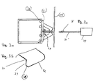
- Fig. 3 (not under claim 1 below) it is shown how the modules 12 on the energy cell, i.e. are attached to the cross member 7 of the energy cell.
- the modules 12 are fastened according to FIG. 3a by means of a clip 25 which has a guide 27 for the modules 12. On this guide 27, the modules 12 are in terms of height and led the deep.
- the modules 12 are also by means of a Snap 26 of the clip attached.
- the locking lug 26 projects through a Recess in the module 12. Pushes through a clip pretension the latch 26 through the module 12 until the module 12 abuts a contact surface 30, with a stop surface 29 Removing the module 12 prevents non-positive.
- a disassembly is possible by means of a dismantling tool 33 (FIG.
- the dismantling tool 33 presses against the contact surface 30 Clip 25 out of module 12. Using an oblique rag 36 of the dismantling tool 33, the module 12 can then be pulled out become. At the end, a deflector slope 31 slides along the wall thickness the module 12 to the outside. If a module 12 is attached can be done with a single clip.
- the Clips can additionally have a dome 37 (FIGS. 7a, 7b). With such clips, modules 12 with a heavy load can additionally be fastened by means of a screw 38, which in the cathedral 37 is screwed.
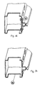
- Fig. 16 shows an alternative type of attachment for the Modules 12.
- a clamping profile 85 can by means of cage nuts be attached to the cross member 7 of the energy cell (not covered by claim 1).
- the clamping profile is formed on the cross member 7, i.e. Clamp profile and cross member are formed in a profile part 86, which is a very easy to assemble embodiment.
- Fig. 18 shows an embodiment with the cross member molded continuous clamping profiles 85 for clamping and Holding the modules 12, in which spring clips 89 are additionally provided are snapped into the cross section 7 and Increase the clamping or holding force of the clamping profiles 85 in that they squeeze them together Such spring chambers 89 are then used if e.g. a high holding force for fittings is needed.
- the spring clips 89 can be in the form of tension hooks be formed as shown in Fig. 18.
- a module 12 is inserted into a clamping profile 85 snapped in so that it is there provided on the module 12 Latch holds.
- a jerk that causes the latch leaves the springs of the clamping profiles 85, the module could subtracted from. This is done by applying the spring clips 89 prevents the holding force of the clamping profiles 85 so increase that module 12 cannot be easily removed can.
- a tool e.g. a spatula-like Tool pushed from the front through the clamping profile 85 to the rear until they fall into the cutout in cross member 7.
- the modules 12 all have the same main dimensions and the same type of attachment to the cross beams 7. All modules 12 are interchangeable.
- the modules 12 are provided in the form of a module set, which consists of at least the following individual modules:
- the dummy or empty module 62 is the base unit for the equipped modules.
- the empty module 62 consists of a flat one Area with a rectangular format and is on all four sides canted. The side surfaces have cutouts for cable entries. The top and bottom faces have an or several holes or stampings to the empty module 62 to clip a cross beam 7.
- the removal module 55 has a greater depth than the others However, modules have the same dimensions in height and in the Width.
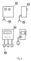
- a distribution module 56 (see also Fig. 15), in which the on-site supply line 60 contains terminals and fuses for the remaining modules. It also contains at least one Outgoing socket 58.
- the removal modules 55 have at least one 220 V or 380 V socket. All removal modules 55 are included provide a cable with an input connector. The removal modules 55 are thereby supplied by the distribution module 56. With longer ones It is possible to provide extension cables for distances, which are guided in the horizontal installation space while short distances via lines in recesses 63 behind the Modules can be bridged. Can continue Coupling pieces 61 may be provided so that on an outlet socket 58 a branch for connecting a plurality of removal modules 55 can be formed on an outgoing line. That way it is readily possible to locate the removal modules 55 change.
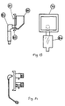
- the sanitary module carries the sanitary, gas and clean gas fittings.
- two rows of fittings can be stacked be set so that on a module with 300 by 300 mm 5 fittings can be positioned.
- the fittings show in 14, an internal thread in the rear area on.
- the connection is made with a connection bracket, which also ensures the downward deflection.
- the connection angle has a long external thread through which the connection to the valve he follows.
- the valve is attached to the module housing with a lock nut pressed and fastened there. By separating between the sanitary connection and the mechanical fastening of the Assembly is greatly facilitated. The previous attachment locking the valve often led to leaks, because the valve could only be turned to the vertical position.
- connection bracket also has a screw connection or connection coupling on which a connection hose is attached.
- this is Hose inserted into a screw connection or coupling. This is located in a T-piece of the through line, which is located in the room. Since all vertical stub lines with hoses are executed, the module 12 can be easily disassembled and be removed from the holding position. Then the hoses disassembled and the module can be positioned elsewhere become. It is also a fitting retrofit possible, and retrofitting of the same media can be done easily, by simply inserting an additional coupling piece into the Branch line is inserted.
- a pool module carries a drain pool on the module body 80.
- the drain basin 80 is screwed from the inside of the module or glued to the module. That depends on the pool material from. Ceramic basins, for example, have to be glued.
- the pool has a nozzle 83 at the back, which together with a bow 82 with a seal forms a sanitary connection.
- a siphon 84 is connected behind the bend. Subsequently the vertical branch line is connected to the ground line.
- the installation of the pool module in the energy cell has a crucial one Advantage, because it creates a clear separation between the energy cell and the furniture, i.e. achieved the work table is in front of the energy cell. In addition, the pool module be replaced.
- Tripod module (Fig. 10)
- Tripods have so far mostly been used for constructional reasons Connection to the glass shelf provided. However, that poses again a combination of non-interconnected components represents, so the use of a tripod module the better System solution is.
- the tripod holder 67 are from behind a screw 68 attached.
- Shelves are an important component of a laboratory work station.
- Storage holders 70 are, for example, on the storage module Screws 74 attached.
- the storage holder 70 can grid holes 71, on which shelves of different depths can be attached.
- the tray holder 70 can on one Module or attached to adjacent modules, to achieve a wider range.
- the glass shelves are also attached to modules.
- the glass holding profiles 76 are by means of screws 77 over the module with the Cross member 7 screwed.
- the glass shelf modules can be like that Storage modules also extend over several module grids.
- any other components can be attached to the modules become.
- wall cabinet modules Modules with veneers to the ceiling or soundproof modules be provided.
- the modules only have to be in grid and in can be attached in the same way.
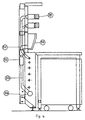
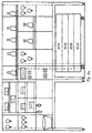
- Fig. 6a two energy cells are shown, above three rows of modules are provided on the work surface of the work table are.
- the bottom row consists of a pool module and then from empty modules.
- the middle row consists of two sanitary modules, one empty module, one sanitary module, two Storage modules and an electrical module.
- the top row is there consisting of a sanitary module, two storage modules and five glass storage modules.
- In front of the unit there is a three module wider Worktable. To the right of this is a veneer that over five modules is enough. For example, there can be a large device stand.
Abstract
Description
Die Erfindung betrifft einen Laborarbeitsplatz mit wenigstens einer Energiezelle mit daran vorgesehener Medienversorgung und Einbauten und einem vor der Energiezelle stehenden Arbeitstisch, wobei die Energiezelle aus zwei vertikalen Ständern aufgebaut ist, die durch wenigstens zwei Querträger miteinander verbunden sind und die Einbauten in Form eines Satzes von austauschbaren Modulen mit verschiedenen Funktionsmöglichkeiten vorgesehen sind, die über der Arbeitstischhöhe mit Halterungen angebracht sind. Ein derartiger Laborarbeitsplatz ist aus der EP-A-0486789 bekannt.The invention relates to a laboratory workstation with at least an energy cell with a provided media supply and internals and one in front of the energy cell Work table, the energy cell consisting of two vertical stands is built up by at least two cross beams with each other are connected and the internals in the form of a set of interchangeable modules with different functions that are above the workbench height Brackets are attached. Such a laboratory workplace is known from EP-A-0486789.
Aus der DE-U-9316330 ist es weiterhin bekannt, bei einem Aufbau für Labor- oder Arbeitstische, der an der Tischplattenoberseite angeordnet ist und mehrere Querträger aufweist, die vertikal distanziert sind, Einbauten direkt an den Querträgern anzubringen.From DE-U-9316330 it is also known for one Setup for laboratory or work tables, the top of the table top is arranged and has several cross members, which are vertically spaced, internals directly on the cross beams to install.
Laborarbeitsplätze sind für Arbeiten in Laboratorien aller Art, insbesondere in Schulen, Hochschulen, Instituten und Firmen vorgesehen. Sie benötigen neben den Arbeitsflächen und Stauräumen eine Anzahl von Medienversorgungen verschiedenster Art sowie weitere Abstellflächen.Laboratory workplaces are for work in laboratories of all Kind, especially in schools, colleges, institutes and companies intended. You need in addition to the work surfaces and storage space a number of different types of media supplies as well further storage areas.
Laborgebäude sind komplizierte Bauwerke, die wegen ihrer Komplexität lange Planungs- und Bauzeiten erfordern. Insbesondere bei öffentlichen Gebäuden sind oftmals die bei der Gebäudeplanung vorgesehenen Nutzer und die tatsächlichen Nutzer beim Einzug verschieden. Darüber hinaus ändern sich in der Forschung die Arbeitsinhalte ständig, was bedeutet, daß ein Labor aufgrund der langen Planungszeit beim Einzug oftmals nicht mehr den Erfordernissen genügt. Da aber bei den bisher üblichen Laborarbeitsplatzsystemen spätere Änderungen kaum möglich oder mit hohen Kosten verbunden sind, werden von den Nutzern in der Regel sehr hohe Anforderungen an die Nutzungsmöglichkeiten gestellt, damit auch erst später aufgenommene Tätigkeiten und Arbeiten ausgeführt werden können, ohne daß erhebliche Änderungen notwendig sind. Diese Anforderungen betreffen insbesondere die Medienbestückung, die Chemikalienbeständigkeit und die Ablageflächen. Das hat wiederum zur Folge, daß bisher Laboratorien in ihrer Anschaffung sehr teuer und meist um 100%, insbesondere in den Medienbestückung, überdimensioniert sind.Laboratory buildings are complex structures because of their Complexity requires long planning and construction times. In particular in public buildings are often those in building planning intended users and the actual users at Indent different. They also change in research the work content constantly, which means that a laboratory is due the long planning time when moving in often no longer meets the requirements enough. But because of the usual laboratory workstation systems later changes hardly possible or with high costs are usually charged by users very high demands on the possible uses, thus also activities and work only started later can be executed without significant changes being necessary are. These requirements particularly concern media assembly, the chemical resistance and the storage space. This in turn has the consequence that laboratories in their Acquisition very expensive and usually around 100%, especially in the Media assembly, are oversized.
Laborarbeitsplätze werden üblicherweise linear parallel zu den Außenwänden eines Laborraumes angeordnet. Ein Standardarbeitsplatz der eingangs genannten Art umfaßt eine Energiezelle mit daran vorgesehenen Medienversorgungen. Die Energiezelle besteht aus zwei vertikalen Ständern, die mit Querträgern verbunden sind. Im unteren Bereich befinden sich die fest installierten Durchgangsleitungen für die Medien, die mehrere Arbeitsplätze miteinander verbinden. In einer Höhe von etwa 900 bis 1200 mm ist eine Medienleiste vorgesehen, in der linear nebeneinander Medienarmaturen angebracht sind. Die Medienarmaturen werden von vorne in die Medienleiste eingeschraubt und oberhalb der Medienleiste befindet sich über die gesamte Breite der Energiezelle ein Elektrokanal, in den Elektroentnahmen und Absicherungen eingebaut sind. Oberhalb des Elektrokanales befinden sich weitere Einbauten, beispielsweise Glas- und Geräteablagen, die wiederum über die gesamte Breite der Energiezelle gehen. Vor der Energiezelle steht ein Arbeitstisch, beispielsweise aus einem Stahlgestell oder einem tragenden Unterbau, auf dem eine Tischplatte angeordnet ist.Laboratory workplaces are usually linear parallel to arranged on the outer walls of a laboratory room. A standard workplace The type mentioned at the beginning comprises an energy cell with the provided media supplies. The energy cell consists of two vertical stands connected with cross members are. The permanently installed are in the lower area Passage lines for the media, which have multiple workplaces connect with each other. At an altitude of around 900 to A media bar is provided at 1200 mm, in the linear next to each other Media fittings are attached. The media fittings are screwed into the media bar from the front and above the media bar is located across the entire width of the energy cell an electrical channel in which electrical withdrawals and fuses are installed. Are located above the electrical duct other internals, such as glass and equipment trays, the again go across the entire width of the energy cell. Before the Energy cell is a work table, for example from a Steel frame or a supporting substructure on which a table top is arranged.
Diese übliche Ausbildung eines Laborarbeitsplatzes hat die
folgenden Nachteile:
Aus dem deutschen Gebrauchsmuster DE-U-90 17 222.3 ist ein Laborarbeitsplatz bekannt, bei dem an Stelle von vertikalen Ständern, die üblicherweise rohrförmig ausgebildet sind, ein Dreieckständer vorgesehen ist. Mit Hilfe eines derartigen Dreieckständers können Ständerkombinationen zusammengestellt werden. Es sind somit Innen- und Außenecken möglich und durch Vorspringen der Energieleisten kann eine punktförmige starke Bestückung in Form einer Säule erzielt werden.From the German utility model DE-U-90 17 222.3 is a Laboratory workplace known, instead of vertical Stands, which are usually tubular Triangular stand is provided. With the help of such a triangular stand stand combinations can be put together. Internal and external corners are thus possible and by projecting the energy strips can be a punctiform strong assembly can be achieved in the form of a column.
Dieses bekannte Laborarbeitsplatzsystem ist jedoch hinsichtlich der Medieninstallation stark eingeschränkt. So ist die Medienentnahme nur in vertikalen Pfosten möglich, die darüber hinaus in Elektro- und Sanitärpfosten aufgeteilt sind. Das hat zur Folge, daß eine Medienentnahme nur punktförmig in Abständen der Rasterbreite von 1200 bzw. 1500 mm möglich ist. Das stellt eine starke Einschränkung der Flexibilität dar. Die Installationsführung der Leitungen ist weiterhin sehr kompliziert, da alle Stichleitungen in den engen Dreieckständern geführt werden müssen. Das ist bereits bei der ersten Installation aufwendig, Umbauten werden dadurch erheblich erschwert. Wenn die Medien von der Decke her zugeführt werden, muß darüber hinaus eine Energiesäule gesetzt werden. An der Stelle dieser Säule ist keinerlei Bestückung möglich, was einen hohen Platzverlust darstellt. Die Dreieckständer sind für die Medienführung andererseits zu klein. Schließlich werden die Ablagen an den vertikalen Pfosten befestigt, so daß diese von der Anordnung und Position der Pfosten abhängen.However, this known laboratory workstation system is regarding media installation is severely restricted. That's how it is Media removal is only possible in vertical posts above it are also divided into electrical and sanitary posts. That has As a result, media removal is only punctiform at intervals the grid width of 1200 or 1500 mm is possible. That poses severely limits flexibility. The installation guide the lines is still very complicated because all stub lines are routed in the narrow triangular stands have to. This is complex even with the first installation, Conversions are made considerably more difficult. If the media from an energy column must also be supplied to the ceiling be set. There is no one in the place of this column Equipping possible, which represents a large loss of space. The Triangular stands, on the other hand, are too small for media management. Finally, the shelves are attached to the vertical posts, so this depends on the arrangement and position of the posts depend.
Das aus dem deutschen Gebrauchsmuster DE-U-90 17 222.3 bekannte Laborarbeitsplatzsystem hat somit in der Grundrißgestaltung gegenüber herkömmlichen Systemen Vorteile, ist jedoch gegenüber den Standardsystemen in Hinblick auf die Medienbestückung eher nachteilig anzusehen.The known from the German utility model DE-U-90 17 222.3 Laboratory workstation system thus has the floor plan advantages over conventional systems, however, is over the standard systems in terms of media assembly rather to look at disadvantageously.
Aus der EP-A-0 486 789 ist ein weiteres Laborarbeitsplatzsystem bekannt, das aus perforierten Vertikalständern und perforierten Traversen aufgebaut ist. Die Durchgangsleitungen werden innerhalb von Ausbrüchen der Ständer gefahren und die vertikalen Stich- und Zugangsleitungen verlaufen innerhalb der perforierten Traversen. Dieses Laborarbeitsplatzsystem ist in Endlosbauweise aufgebaut, so daß sich an jedem Stoß nur ein Ständerelement befindet. Bei diesem System sind weiterhin die Arbeitstische in die Ständerelemente eingehängt, so daß die Ständer als tragende Teile der Arbeitstische funktionieren. Die ELT-Bestückung befindet sich in Elektromodulen, die Sanitärentnahme in Sanitärmodulen, wobei diese Module eine Größe von etwa 600 mal 300 mm haben. Ablagen sind an Querrohren befestigt, die vor den Ständern verlaufen. Es ist weiterhin vorgeschlagen, daß die Ständerelemente gleichzeitig die Laborwände darstellen.Another laboratory workstation system is known from EP-A-0 486 789 known, that of perforated vertical stands and perforated Truss is built. The through lines are driven inside outbreaks of the stand and the vertical Stub and access lines run inside the perforated Traverses. This laboratory workstation system is in endless construction built up so that there is only one stand element at each joint located. With this system, the work tables are still in the stand elements hooked in, so that the stand as a load-bearing Parts of the work tables work. The ELT assembly is located in electrical modules, the sanitary removal in sanitary modules, these modules being approximately 600 by 300 mm in size to have. Trays are attached to cross tubes in front of the stands run. It is also proposed that the stand elements simultaneously represent the laboratory walls.
Das aus der EP-A-0 486 789 bekannte Laborarbeitsplatzsystem hat auf den ersten Blick Vorteile, erweist sich jedoch bei näherer Betrachtung als nicht praxisgerecht. Die verwendete Endlosbauweise erschwert nämlich eine exakte Größenberechnung durch den Nutzer. Zudem gibt es bei der Demontage unfertige Teilsysteme, die nicht weiter verwendet werden können. Weiterhin ist die Einbringung der Durchgangsleitungen sehr unpraktisch, da bei jedem Ständer Verschraubungen gesetzt werden müssen. Eine Nachrüstung ist mit erheblichem Aufwand verbunden. Die Verwendung der Ständer als tragende Tischelemente ist gleichfalls unpraktisch, da bei Änderungen der gesamte Tisch demontiert werden muß. Die verwendeten sehr großen Medienmodule sind ebenfalls unpraktisch, da sie nicht demontierbar sind. Zudem ist kein Austausch eines Medienmodules mit einem Ablagemodul möglich.The laboratory workstation system known from EP-A-0 486 789 has advantages at first glance, but proves to be closer Consideration as not practical. The endless construction used This makes an exact size calculation difficult the user. There are also unfinished subsystems during disassembly, that can no longer be used. Furthermore, the Introduction of the through lines very impractical because every stand must be screwed. An upgrade is associated with considerable effort. The usage the stand as supporting table elements is also impractical, since the entire table can be dismantled if changes are made got to. The very large media modules used are also impractical, since they are not removable. In addition, there is no exchange of a media module with a storage module possible.
Die der Erfindung zugrunde liegende Aufgabe besteht dem gegenüber darin, den Laborarbeitsplatz der eingangs genannten Art so auszubilden, daß er eine hohe Flexibilität zur Umrüstung, Anpassung u.s.w. während der Planungs-, Bau- und Nutzungsphase hat.The object underlying the invention is in contrast in the laboratory workplace of the type mentioned at the beginning to be trained so that he has a high flexibility for retrofitting, adaptation etc. during the planning, construction and use phase Has.
Diese Aufgabe wird gemäß der Erfindung dadurch gelöst, daß die Halterungen an den Querträgern der Energiezelle vorgesehen sind und aus Klemmprofilen bestehen, die in einem Stück mit den Querträgern ausgebildet sind.This object is achieved according to the invention in that the brackets are provided on the cross beams of the energy cell are and consist of clamping profiles that are in one piece with the Cross beams are formed.
Bei der erfindungsgemäßen Ausbildung ist eine große Flexibilität insofern erzielt, als Änderungen während der Planungsphase, bei der Montage, bei der die Nutzer des Labors die Laboreinrichtung zum ersten Mal körperlich sehen, und bei Nutzungsänderungen leicht und weitgehend ohne Inanspruchnahme von Fachfirmen möglich sind. Das eröffnet einen Weg, Laboratorien nutzungsgerecht einzurichten, ohne daß diese bei der Planung stark überdimensioniert werden. Das Grundprinzip der erfindungsgemäßen Ausbildung, mit der das erreicht wird, besteht dabei darin, daß eine strenge Modularität aller Bauelemente eingehalten wird, alle Module austauschbar sind und der Aufbau rasterartig aus Energiezellen und entsprechenden Modulen aufgebaut ist. Im Gegensatz zu bekannten Systemen ist eine Trennung der Medienversorgung d.h. der Energiezelle und der Möbel, d.h. der vor der Energiezelle stehenden Arbeitstische vorgesehen und wird eine Endlosbauweise vermieden.There is great flexibility in the design according to the invention achieved in that changes during the planning phase, during assembly where the users of the laboratory set up the laboratory see for the first time physically, and when changes in use easily and largely without the use of specialist companies possible are. This opens up a way for laboratories to be suitable for use to set up without being strong in planning be oversized. The basic principle of the invention Training with which this is achieved consists in that a strict modularity of all components is observed, all Modules are interchangeable and the structure is made up of energy cells and the corresponding modules. In contrast to known systems is a separation of the media supply i.e. the energy cell and the furniture, i.e. the one in front of the energy cell standing work tables and is an endless construction avoided.
Besonders bevorzugte Ausgestaltungen des erfindungsgemäßen
Laborarbeitsplatzes sind Gegenstand der Patentansprüche 2 bis
11. Particularly preferred configurations of the invention
Laboratory workplace are the subject of
Im folgenden wird anhand der zugehörigen Zeichnung ein
besonders bevorzugtes Ausführungsbeispiel näher
beschrieben. Es zeigen
Ein Laborarbeitsplatz besteht im wesentlichen aus einer Energiezelle und einem davor stehenden Arbeitstisch. Der Arbeitstisch trägt eine Arbeitsplatte, auf dem beispielsweise Versuche ablaufen.A laboratory work station essentially consists of one Energy cell and a work table in front of it. The work table carries a countertop on which, for example Trials are running.
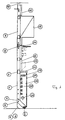
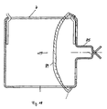
Wie es in Fig. 1 dargestellt ist, ist die Energiezelle aus
einem Tragechassis aufgebaut, an dem Module angebracht werden
können. Das Tragechassis besteht aus zwei vertikalen Ständern
oder Ständerprofilen 1, die an ihrer Innenseite Loch- oder Rasterbohrungen
3 zum Anbringen von Querträgern aller Art aufweisen.
Am unteren Ende der Ständerprofile 1 befindet sich ein
Ständerfuß 2, der über eine Nivellierungseinrichtung 4 Bodenunebenheiten
ausgleicht. Die Ständerprofile 1 gehen nicht bis
zum Boden sondern lassen einen Spalt 5 zum Boden, so daß die
Ständerprofile 1 unabhängig von den Bodenfliesen 6 angeordnet
werden können. Über Tischplattenhöhe sind die Ständerprofile 1
mit Querträgern 7 verbunden, die an den Rasterbohrungen 3 höhenverstellbar
befestigt sind. Die Ständerprofile 1 können im Bedarfsfall
mittels einer Ständerverlängerung 9 aus einem weiteren
Ständerprofil bis zur Decke verlängert werden. Sie können dann
mittels eines Deckenankers 10 an der Decke befestigt sein. Auf
der Höhe der Arbeitstischplatte, d.h. auf einer Höhe von 720
oder 900 mm befindet sich eine Konsole 11. Der Raum zwischen dem
Ständerfuß und der Konsole 11 ist der Installationsraum 18 für
horizontale Versorgungsleitungen. Im oberen Teil dieses Raumes
sind die ELT-Durchgangsleitungen 19 geführt, darunter liegen die
Sanitärleitungen 20. Es können weiterhin Schnüffelleitungen und
Abwasserleitungen 21 in diesem Raum geführt sein.As shown in Fig. 1, the energy cell is off
a support chassis to which modules are attached
can. The carrying chassis consists of two vertical stands
or stand
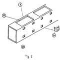
Oberhalb der Konsole 11 sind wenigstens zwei Querträger 7
vorgesehen, an denen wenigstens eine horizontale Reihe von Modulen
12 befestigt werden kann. Die Module 12 können bis zur Decke
reichen. Es ist jedoch gleichfalls möglich, Hängeschränke 15
oder Verblendungen 16 an den Querträgern 7 zu befestigen, wobei
dann, wenn die Verblendungen 16 schallhemmend ausgeführt sind,
die Energiezelle auch als Raumtrenner oder Raumteiler dienen
kann. Wie es in Fig. 2 dargestellt ist, sind die Querträger 7
mit vertikalen Ausnehmungen 22 versehen, durch die bei hoher
Stabilität der Querträger 7 vertikale Leitungen geführt werden
können. Diese Leitungen können Stichleitungen zu Armaturen oder
Zugangsleitungen von der Decke in die Energiezelle sein.At least two
An den Querträgern 7 sind frontseitig Ausstanzungen 23
vorgesehen, in die zum Beispiel Käfigmuttern 24 eingelegt werden
können. Es können jedoch auch Klemmteile zur Aufnahme von Blechschrauben
eingelegt sein. Mittels Clips 25 oder Klemmprofilen
können verschiedene Module 12 am Querträger 7 angebracht werden.
Die Module 12 haben eine Tiefe von etwa 25 mm.On the
Bei einem derartigen Aufbau ergibt sich für die gesamte
Energiezelle eine eindeutige Festlegung, wie die Medienleitungen
unabhängig voneinander geführt werden können. Die Durchgangsleitungen
sind im horizontalen Raum 18 geführt, der Raum zwischen
den vertikalen Ständerprofilen 1 ist für vertikale Leitungen
reserviert, die ggf. durch die Ausnehmungen 22 in den Querträgern
7 geführt sind. Im Raum 13 innerhalb der Module 12 können
im Bedarfsfall kurze Querleitungen zwischen den Modulen
gelegt sein.With such a structure, the result for the entire
Energy cell a clear definition of how the media lines
can be managed independently. The through lines
are guided in the
In Fig. 3 (nicht unter Anspruch 1 follend) ist dargestellt, wie die Module 12 an der Energiezelle,
d.h. am Querträger 7 der Energiezelle befestigt sind.
Die Befestigung der Module 12 erfolgt gemäß Fig. 3a mittels
eines Clip 25, der eine Führung 27 für die Module 12 aufweist.
An dieser Führung 27 sind die Module 12 bezüglich der Höhe und
der Tiefe geführt. Die Module 12 sind zusätzlich mittels einer
Rastnase 26 des Clips befestigt. Die Rastnase 26 ragt durch eine
Ausnehmung in das Modul 12. Durch eine Clipvorspannung schiebt
sich die Rastnase 26 durch das Modul 12, bis das Modul 12 an
einer Anlagefläche 30 anliegt, wobei eine Anschlagfläche 29 ein
Herausnehmen des Moduls 12 kraftschlüssig verhindert. Eine Demontage
ist mittels eines Demontagewerkzeuges 33 (Fig. 3c) möglich.
Das Demontagewerkzeug 33 drückt an der Anlagefläche 30 den
Clip 25 aus dem Modul 12 heraus. Mittels eines schrägen Lappens
36 des Demontagewerkzeuges 33 kann dann das Modul 12 herausgezogen
werden. Am Ende gleitet eine Abweiserschräge 31 an der Wanddicke
des Moduls 12 nach außen. Soll ein Modul 12 befestigt
werden, so kann das auch mit einem einzelnen Clip erfolgen. Die
Clips können zusätzlich einen Dom 37 aufweisen (Fig. 7a, 7b).
Mit derartigen Clips können Module 12 mit schwerer Last zusätzlich
mittels einer Schraube 38 befestigt werden, die in den Dom
37 geschraubt wird.In Fig. 3 (not under
Fig. 16 zeigt eine alternative Befestigungsart für die
Module 12. Anstelle von Clips sind durchgehende Klemmprofile 85
an den Querträgern vorgesehen, die die Module 12 halten. Das ist
dann von Vorteil, wenn für Verblendungen größere Module 12 benötigt
werden. Ein derartiges Klemmprofil 85 kann mittels Käfigmuttern
am Querträger 7 der Energiezelle befestigt sein (nicht unter Anspruch 1 fallend). Nach
Anspruch 1 ist das Klemmprofil am Querträger 7 angeformt, d.h.
Klemmprofil und Querträger sind in einem Profilteil 86 ausgebildet,
was ein sehr montagefreundliches Ausführungsbeispiel darstellt.Fig. 16 shows an alternative type of attachment for the
Fig. 18 zeigt ein Ausführungsbeispiel mit am Querträger
angeformten durchgehenden Klemmprofilen 85 zum Aufklemmen und
Halten der Module 12, bei dem zusätzlich Federklammern 89 vorgesehen
sind, die im Querprofil 7 eingeschnappt sind und die
Klemm- oder Haltekraft der Klemmprofile 85 dadurch erhöhen, daß
sie diese zusammendrücken. Derartige Federkammern 89 werden dann
eingesetzt, wenn z.B. bei Armatureinbauten eine hohe Haltekraft
benötigt wird. Die Federklammern 89 können in Form von Spannhaken
ausgebildet sein, wie es in Fig. 18 dargestellt ist.Fig. 18 shows an embodiment with the cross member
molded continuous clamping profiles 85 for clamping and
Holding the
Bei der Montage wird ein Modul 12 in ein Klemmprofil 85
eingeschnappt, so daß es dort mit der am Modul 12 vorgesehen
Rastnase hält. Durch einen Ruck, der bewirkt, daß die Rastnase
die Federn der Klemmprofile 85 verläßt, könnte das Modul jedoch
abgezogen werden. Das wird durch das Aufbringen der Federklammern
89 verhindert, die die Haltekraft der Klemmprofile 85 so
erhöhen, daß das Modul 12 nicht ohne weiteres entfernt werden
kann.During assembly, a
Wenn die zusätzliche Federklammern 89 nicht benötigt werden,
können sie mit einem Werkzeug, z.B. einem spachtelartigen
Werkzeug von vorne durch das Klemmprofil 85 nach hinten geschoben
werden, bis sie in den Ausschnitt im Querträger 7 fallen.If the additional spring clips 89 are not required,
you can use a tool, e.g. a spatula-like
Tool pushed from the front through the clamping
Die Module 12 haben alle die gleichen Hauptabmessungen und
die gleiche Art der Befestigung an den Querträgern 7. Alle Module
12 sind gegeneinander austauschbar.The
Die Module 12 sind in Form eines Modulsatzes vorgesehen,
der wenigstens aus den folgenden Einzelmodulen besteht:The
Das Blind- oder Leermodul 62 ist die Basiseinheit für die
bestückten Module. Das Leermodul 62 besteht aus einer ebenen
Fläche mit rechteckigem Format und ist an allen vier Seiten
umgekantet. Die seitlichen Flächen haben Aussparungen für Kabeldurchführungen.
Die oberen und unteren Flächen weisen eine oder
mehrere Bohrungen oder Ausprägungen auf, um das Leermodul 62 an
einen Quertäger 7 zu clipsen.The dummy or empty module 62 is the base unit for the
equipped modules. The empty module 62 consists of a flat one
Area with a rectangular format and is on all four sides
canted. The side surfaces have cutouts for cable entries.
The top and bottom faces have an or
several holes or stampings to the empty module 62
to clip a
Das Entnahmemodul 55 hat eine größere Tiefe als die anderen
Module jedoch die gleichen Abmessungen in der Höhe und in der
Breite. Ein Verteilermodul 56 (siehe auch Fig. 15), in das die
bauseitige Zuleitung 60 führt, enthält Klemmen und Sicherungen
für die restlichen Module. Es enthält weiterhin wenigstens eine
Abgangsbuchse 58. Die Entnahmemodule 55 weisen wenigstens eine
220 V oder 380 V Steckdose auf. Alle Entnahmemodule 55 sind mit
einem Kabelstück mit Eingangsstecker versehen. Die Entnahmemodule
55 werden dadurch vom Verteilermodul 56 versorgt. Bei längeren
Wegstrecken ist es möglich, Verlängerungskabeln vorzusehen,
die im horizontalen Installationsraum geführt sind, während
kurze Wegstrecken über Leitungen in Aussparungen 63 hinter den
Modulen überbrückt werden können. Weiterhin können
Kupplungsstücke 61 vorgesehen sein, so daß an einer Abgangsbuchse
58 eine Verzweigung zum Anschluß von mehreren Entnahmemodulen
55 an einer Abgangsleitung gebildet werden kann. In dieser Weise
ist es ohne weiteres möglich, den Ort der Entnahmemodule 55 zu
verändern.The
Das Sanitärmodul trägt die Sanitär-, Gas- und Reingasarmaturen.
In einem Modul können zwei Reihen von Armaturen übereinander
gesetzt werden, so daß auf einem Modul mit 300 mal 300 mm
5 Armaturen positioniert werden können. Die Armaturen weisen in
der in Fig. 14 dargestellten Weise im hinteren Bereich ein Innengewinde
auf. Der Anschluß erfolgt mit einem Anschlußwinkel,
der auch für die Umlenkung nach unten sorgt. Der Anschlußwinkel
hat ein langes Außengewinde, über das der Anschluß an der Armatur
erfolgt. Die Armatur wird mit einer Kontermutter an das Modulgehäuse
gepreßt und dort befestigt. Durch die Trennung zwischen
dem Sanitäranschluß und der mechanischen Befestigung des
Moduls wird die Montage stark erleichert. Die bisherige Befestigung
durch Arretieren der Armatur führte oft zu Undichtigkeiten,
da die Armatur nur bis zur Verikalposition gedreht werden durfte.
Der Anschlußwinkel weist weiterhin eine Anschlußverschraubung
bzw. Anschlußkupplung auf, an der ein Anschlußschlauch
befestigt wird. Auf der anderen Seite wird dieser
Schlauch in eine Verschraubung oder Kupplung gesteckt. Diese befindet
sich in einem T-Stück der Durchgangsleitung, welche sich
im Raum befindet. Da alle vertikalen Stichleitungen mit Schläuchen
ausgeführt sind, kann das Modul 12 leicht demontiert und
aus der Halteposition entfernt werden. Dann können die Schläuche
demontiert werden und kann das Modul an einer anderen Stelle positioniert
werden. Es ist auch eine Nachrüstung einer Armatur
möglich, und Nachrüstungen gleicher Medien können problemlos erfolgen,
indem einfach ein zusätzliches Kupplungsstück in die
Stichleitung eingefügt wird.The sanitary module carries the sanitary, gas and clean gas fittings.
In a module, two rows of fittings can be stacked
be set so that on a module with 300 by 300
Ein Beckenmodul trägt auf dem Modulkörper ein Ablaufbecken
80. Das Ablaufbecken 80 wird von der Modulinnenseite her verschraubt
oder mit dem Modul verklebt. Das hängt von dem Beckenwerkstoff
ab. Keramikbecken müssen beispielsweise verklebt werden.
Das Becken weist hinten einen Stutzen 83 auf, der zusammen
mit einem Bogen 82 mit Dichtung einen Sanitäranschluß bildet.
Hinter dem Bogen wird ein Syphon 84 angeschlossen. Anschließend
wird die vertikale Stichleitung mit der Grundleitung verbunden.
Der Einbau des Beckenmoduls in die Energiezelle hat einen entscheidenden
Vorteil, da damit eine eindeutige Trennung zwischen
der Energiezelle und dem Möbel, d.h. dem Arbeitstisch erzielt
ist, der vor der Energiezelle steht. Zudem kann das Beckenmodul
ausgetauscht werden.A pool module carries a drain pool on the
Stative wurden bisher aus konstruktiven Gründen meist in
Verbindung mit der Glasablage vorgesehen. Das stellt jedoch
wiederum eine Kombination von nicht miteinander verbundene Bauteilen
dar, so daß der Einsatz eines Stativmoduls die bessere
Systemlösung ist. Die Stativhalter 67 werden von hinten mit
einer Schraube 68 befestigt.Tripods have so far mostly been used for constructional reasons
Connection to the glass shelf provided. However, that poses
again a combination of non-interconnected components
represents, so the use of a tripod module the better
System solution is. The
Ablagen sind ein wichtiges Bauteil eines Laborarbeitsplatzes. Am Ablagemodul sind Ablagehalter 70 beispielsweise mit Schrauben 74 befestigt. Die Ablagehalter 70 können Rasterbohrungen 71 aufweisen, an denen Ablageböden verschiedener Tiefe befestigt werden können. Die Ablagehalter 70 können auf einem Modul oder auf nebeneinander liegenden Modulen befestigt werden, um eine größere Spannbreite zu erzielen.Shelves are an important component of a laboratory work station. Storage holders 70 are, for example, on the storage module Screws 74 attached. The storage holder 70 can grid holes 71, on which shelves of different depths can be attached. The tray holder 70 can on one Module or attached to adjacent modules, to achieve a wider range.
Auch die Glasablagen werden an Modulen befestigt. Die Glashalteprofile
76 sind mittels Schrauben 77 über das Modul mit dem
Querträger 7 verschraubt. Die Glasablagemodule können wie die
Ablagemodule auch über mehrere Modulraster reichen.The glass shelves are also attached to modules. The glass holding profiles
76 are by means of
An den Modulen können noch beliebige weitere Bauteile angebracht werden. Es können beispielsweise Hängeschrankmodule, Module mit Verblendungen zur Decke oder schallhemmende Module vorgesehen sein. Die Module müssen nur im Raster liegen und in der gleichen Weise befestigt werden können.Any other components can be attached to the modules become. For example, wall cabinet modules, Modules with veneers to the ceiling or soundproof modules be provided. The modules only have to be in grid and in can be attached in the same way.
Durch den oben beschriebenen modularen Aufbau ergibt sich eine große Planungsfreiheit, wobei weiterhin ohne weiteres erkennbar ist, daß auch bei der Montage noch Änderungen vorgenommen werden können. Ein weiterer Vorteil besteht darin, daß der Laborarbeitsplatz später problemlos an neue Anforderungen angepaßt werden kann.The modular structure described above results in a great freedom of planning, while still recognizable is that changes are also made during assembly can be. Another advantage is that the Laboratory workplace later easily adapted to new requirements can be.
Wichtig für den Gesamtaufbau des Laborarbeitssystems ist
die Anordnung der Energiezelle und Module nebeneinander und/oder
hintereinander in Form eines festen Rasters. Alle Energiezellen
haben an beiden Seiten jeweils ein Ständerprofil 1, an einem
Rücken-an-Rücken-Stoß stehen somit zwei Ständer. Damit können
leicht bei einem Umbau ganze Energiezellenelemente weggenommen
werden und an einer anderen Stelle wiederverwendet werden.It is important for the overall structure of the laboratory work system
the arrangement of the energy cell and modules next to each other and / or
in a row in the form of a fixed grid. All energy cells
have a
Ein Beispiel für diese Variabilität ist in Fig. 6a, b dargestellt.An example of this variability is shown in Fig. 6a, b.
In Fig. 6a sind zwei Energiezellen gezeigt, wobei oberhalb der Arbeitsfläche des Arbeitstisches drei Modulreihen vorgesehen sind. Die unterste Reihe besteht links aus einem Beckenmodul und anschließend aus Leermodulen. Die mittlere Reihe besteht aus zwei Sanitärmodulen, einem Leermodul, einem Sanitärmodul, zwei Ablagemodulen und einem Elektromodul. Die oberste Reihe besteht aus einem Sanitärmodul, zwei Ablagemodulen und fünf Glasablagemodulen. Vor der Einheit steht ein über drei Module breiter Arbeitstisch. Rechts davon besteht eine Verblendung, die über fünf Module reicht. Dort kann beispielsweise ein großes Gerät stehen.In Fig. 6a two energy cells are shown, above three rows of modules are provided on the work surface of the work table are. The bottom row consists of a pool module and then from empty modules. The middle row consists of two sanitary modules, one empty module, one sanitary module, two Storage modules and an electrical module. The top row is there consisting of a sanitary module, two storage modules and five glass storage modules. In front of the unit there is a three module wider Worktable. To the right of this is a veneer that over five modules is enough. For example, there can be a large device stand.
Fig. 6b zeigt einen möglichen Umbau. Die Sanitärmodule wurden nicht verändert. Es wurde ein Elektromodul umgesetzt und es kamen mehrere Ablagemodule hinzu. Zusätzlich wurde ein weiterer Tisch vor die Einheit gesetzt. Damit ist ein Umbau von einem Gerätearbeitsplatz zu einem Laborarbeitsplatz erfolgt. Diese Umbauten können ohne in Anspruchnahme einer Fachfirma vom Laboranten selbst vorgenommen werden. Natürlich können auch die Sanitärmodule umgebaut werden oder kann durch Anbringen weiterer Module der Tisch von einer Arbeitshöhe von 900 mm auf 720 mm umgebaut werden.6b shows a possible conversion. The sanitary modules were not changed. An electrical module was implemented and it several storage modules were added. In addition, another Place the table in front of the unit. This is a conversion of one Device workplace to a laboratory workplace. This Modifications can be carried out without the need of a specialist company from the laboratory technician be made yourself. Of course they can too Sanitary modules can be rebuilt or can be added by attaching Modules of the table from a working height of 900 mm to 720 mm be rebuilt.
Das obige Beispiel zeigt, daß die Arbeitstische von der Energiezelle vollständig unabhängig sind. Da die vertikalen Ständerprofile 1 der Energiezellen nicht sichtbar sind, müssen die Raster nicht aufeinander abgestimmt sein, als Material für die Ständerprofile 1 kann ein kostengünstiges Material ohne hochwertige Oberfläche, d.h. beispielsweise mit einer Verzinkung verwandt werden, was die Kosten herabsetzt.The above example shows that the work tables from the Energy cells are completely independent. Because the vertical Stand profiles 1 of the energy cells are not visible, must the grids are not coordinated as material for the stand profiles 1 can be an inexpensive material without high quality surface, i.e. for example with galvanizing be used, which reduces the cost.
Claims (11)
- A laboratory work station comprising at least one energy cell with a supply of media provided thereon, and comprising built-in units, and comprising a workbench situated in front of the energy cell, wherein the energy cell is constructed from two vertical pillars which are joined to each other by at least two crossbeams, and the built-in units are provided in the form of an interchangeable set of modules with different functional possibilities which are mounted above the height of the workbench by holding devices, characterised in that the holding devices are provided on the crossbeams of the energy cell and consist of clamping sections which are formed in one piece with the crossbeams.
- A laboratory work station according to claim 1, characterised in that a plurality of energy cells and the modules are disposed side by side and/or one behind another in a defined grid.
- A laboratory work station according to claim 1, characterised by spring clips which are inserted in the crossbeams and which compress the clamping sections.
- A laboratory work station according to claim 3, characterised in that the spring clips can be pushed backwards from the face of the clamping sections.
- A laboratory work station according to any one of the preceding claims, characterised in that the modules include electrical securing and distribution modules which can be connected to each other via plug-in connectors.
- A laboratory work station according to any one of the preceding claims, characterised in that the modules include sanitation modules which are provided with fittings which are fixed to the back of the sanitation modules, wherein the media connections are independent of the mechanical fixing of the modules.
- A laboratory work station according to any one of the preceding claims, characterised in that the modules for the media connections are connected to the media supplies of the energy cell via flexible lines.
- A laboratory work station according to any one of the preceding claims, characterised in that the modules include drainage modules to which drainage basins are fixed which can be removed from the front.
- A laboratory work station according to any one of the preceding claims, characterised in that the modules include placement modules which have a single or multiple grid width.
- A laboratory work station according to any one of the preceding claims, characterised in that the modules include glass placement modules which have a single or multiple grid width.
- A laboratory work station according to any one of the preceding claims, characterised in that the vertical pillars of the energy cell do not reach as far as the floor.
Applications Claiming Priority (2)
| Application Number | Priority Date | Filing Date | Title |
|---|---|---|---|
| DE19614370 | 1996-04-11 | ||
| DE19614370A DE19614370C1 (en) | 1996-04-11 | 1996-04-11 | Laboratory workplace |
Publications (3)
| Publication Number | Publication Date |
|---|---|
| EP0800865A2 EP0800865A2 (en) | 1997-10-15 |
| EP0800865A3 EP0800865A3 (en) | 1998-08-26 |
| EP0800865B1 true EP0800865B1 (en) | 2003-01-22 |
Family
ID=7791019
Family Applications (1)
| Application Number | Title | Priority Date | Filing Date |
|---|---|---|---|
| EP97105781A Expired - Lifetime EP0800865B1 (en) | 1996-04-11 | 1997-04-08 | Laboratory work station |
Country Status (4)
| Country | Link |
|---|---|
| EP (1) | EP0800865B1 (en) |
| AT (1) | ATE231414T1 (en) |
| DE (2) | DE19614370C1 (en) |
| ES (1) | ES2188812T3 (en) |
Families Citing this family (13)
| Publication number | Priority date | Publication date | Assignee | Title |
|---|---|---|---|---|
| ES2134719B1 (en) * | 1997-04-25 | 2000-05-01 | Munoz Julian Romero | PERFECTED LABORATORY TABLE. |
| EP1273336B1 (en) | 1998-12-25 | 2008-01-23 | Tosoh Corporation | Process for removing organic compounds using combustion catalysts |
| ES2177355B1 (en) * | 1999-02-17 | 2004-11-16 | Burdinola, S. Coop. | MODULAR STRUCTURAL SYSTEM FOR FLUID DRIVES BOTH IN FURNITURE AND LABORATORY OR SIMILAR FACILITIES. |
| FR2791233B1 (en) * | 1999-03-24 | 2003-03-21 | Burdinola S Coop | MODULAR STRUCTURE FOR FLUID CONDUITS IN FURNITURE AND LABORATORY OR SIMILAR FACILITIES |
| DE10154128B4 (en) * | 2001-10-25 | 2009-09-03 | Hermann Schaffitzel | Media cell for a laboratory or the like |
| ES2208046B1 (en) * | 2002-01-10 | 2005-04-01 | Julian Romero Muñoz | MODULAR SYSTEM OF LABORATORY TABLE FACILITIES. |
| ES2234374B1 (en) * | 2002-11-12 | 2006-05-16 | Julian Romero Muñoz | CONSTRUCTION SYSTEM FOR LABORATORY FURNITURE-SHELF. |
| DE102006055000B4 (en) * | 2005-12-15 | 2007-09-20 | GfP (Gesellschaft für Produktivitätsplanung und Produktentwicklung) mbH | Device for providing and / or for storing and / or for producing at least one medium on a work table, and assembly for connection to the work table and system for different media |
| DE202008016891U1 (en) * | 2008-12-19 | 2010-05-12 | VS Vereinigte Spezialmöbelfabriken GmbH & Co. KG | Laboratory workplace |
| DE102009002454A1 (en) * | 2009-04-17 | 2010-10-28 | Waldner Laboreinrichtungen Gmbh & Co. Kg | Media channel for a laboratory device |
| DE102009020726A1 (en) * | 2009-05-11 | 2010-11-25 | Wesemann Gmbh & Co. Kg | Supply system for providing a media supply |
| EP3240129B1 (en) | 2016-04-27 | 2023-12-20 | arc2lab GmbH | System for supplying media |
| DE102017105852A1 (en) * | 2017-03-17 | 2018-09-20 | Wesemann Gmbh | Media supply system |
Family Cites Families (5)
| Publication number | Priority date | Publication date | Assignee | Title |
|---|---|---|---|---|
| FR2411633A1 (en) * | 1977-12-16 | 1979-07-13 | Alsthom Atlantique | Appts. for supporting appts. e.g. in laboratories - includes parallel vertical removable panels and racks |
| US4320935A (en) * | 1979-10-22 | 1982-03-23 | Herman Miller, Inc. | Structural support system with load control |
| US4544214A (en) * | 1982-12-15 | 1985-10-01 | Architectural Resources Cambridge, Inc. | Laboratory furniture system |
| IT1244081B (en) * | 1990-11-21 | 1994-07-05 | Arredi Tecnici Villa Spa | MODULAR SYSTEM FOR THE REALIZATION OF EQUIPPED WALLS AND WORKBENCHES IN PARTICULAR FOR LABORATORIES. |
| DE9316330U1 (en) * | 1993-10-26 | 1994-01-13 | Erfi Ernst Fischer Gmbh & Co | Setup for laboratory or work tables |
-
1996
- 1996-04-11 DE DE19614370A patent/DE19614370C1/en not_active Expired - Fee Related
-
1997
- 1997-04-08 EP EP97105781A patent/EP0800865B1/en not_active Expired - Lifetime
- 1997-04-08 DE DE59709170T patent/DE59709170D1/en not_active Expired - Lifetime
- 1997-04-08 ES ES97105781T patent/ES2188812T3/en not_active Expired - Lifetime
- 1997-04-08 AT AT97105781T patent/ATE231414T1/en active
Also Published As
| Publication number | Publication date |
|---|---|
| EP0800865A2 (en) | 1997-10-15 |
| ATE231414T1 (en) | 2003-02-15 |
| DE59709170D1 (en) | 2003-02-27 |
| DE19614370C1 (en) | 1997-12-18 |
| EP0800865A3 (en) | 1998-08-26 |
| ES2188812T3 (en) | 2003-07-01 |
Similar Documents
| Publication | Publication Date | Title |
|---|---|---|
| EP0800865B1 (en) | Laboratory work station | |
| EP0307620B1 (en) | Work bench | |
| EP0398014B1 (en) | Variable work place furniture system | |
| EP2419979A2 (en) | Media channel for a laboratory device | |
| WO2002008851A2 (en) | Modular functional wall | |
| DE19615759C2 (en) | Control cabinet with base and frame | |
| DE10154128B4 (en) | Media cell for a laboratory or the like | |
| DE1778336A1 (en) | System for assembling box furniture, especially for kitchen furniture | |
| EP0517938B1 (en) | Modular construction system | |
| DE3007229A1 (en) | CABLE DISTRIBUTOR | |
| DE60315580T2 (en) | Laboratory furniture design system | |
| EP1123021A2 (en) | Variable workstation furniture system with vertical columns and horizontal tie-bars | |
| DE1591623B1 (en) | Cabinet for telecommunications equipment | |
| DE3231802A1 (en) | Desk, in particular for office work | |
| DE19956951C2 (en) | Workplace furniture with a furniture frame made of vertical columns and crossbars | |
| DE7037254U (en) | Rack frame | |
| DE3740778A1 (en) | Workplace table | |
| DE19615447A1 (en) | Wall system for exhibition and trade fair stands | |
| DE102021131228A1 (en) | Media column for an arrangement for the distribution of media such as gaseous and liquid media, vacuum, electricity and communication in a laboratory | |
| DE102021104139A1 (en) | media supply system | |
| DE2750517C3 (en) | Flat cable carrier for use especially in telephone exchanges and booster stations (TZV) | |
| DE2804016A1 (en) | Laboratory table esp. for schools - is subdivided into fixed parts for gas, water, electricity installations and movable table tops | |
| DE19507725A1 (en) | Switch cabinet with frame structure and mounting plates | |
| DE1985763U (en) | SUPPORT FOR MOVABLE LABORATORY FURNITURE AND EQUIPMENT. | |
| DE4207282A1 (en) | Free standing adjustable laboratory stand - useful for stacking electrical equipment |
Legal Events
| Date | Code | Title | Description |
|---|---|---|---|
| PUAI | Public reference made under article 153(3) epc to a published international application that has entered the european phase |
Free format text: ORIGINAL CODE: 0009012 |
|
| AK | Designated contracting states |
Kind code of ref document: A2 Designated state(s): AT CH DE ES FR GB LI |
|
| PUAL | Search report despatched |
Free format text: ORIGINAL CODE: 0009013 |
|
| AK | Designated contracting states |
Kind code of ref document: A3 Designated state(s): AT CH DE ES FR GB LI |
|
| 17P | Request for examination filed |
Effective date: 19981230 |
|
| 17Q | First examination report despatched |
Effective date: 20010730 |
|
| GRAG | Despatch of communication of intention to grant |
Free format text: ORIGINAL CODE: EPIDOS AGRA |
|
| GRAG | Despatch of communication of intention to grant |
Free format text: ORIGINAL CODE: EPIDOS AGRA |
|
| GRAH | Despatch of communication of intention to grant a patent |
Free format text: ORIGINAL CODE: EPIDOS IGRA |
|
| GRAH | Despatch of communication of intention to grant a patent |
Free format text: ORIGINAL CODE: EPIDOS IGRA |
|
| GRAA | (expected) grant |
Free format text: ORIGINAL CODE: 0009210 |
|
| AK | Designated contracting states |
Kind code of ref document: B1 Designated state(s): AT CH DE ES FR GB LI |
|
| REG | Reference to a national code |
Ref country code: GB Ref legal event code: FG4D Free format text: NOT ENGLISH |
|
| REG | Reference to a national code |
Ref country code: CH Ref legal event code: NV Representative=s name: NOVAGRAAF INTERNATIONAL SA Ref country code: CH Ref legal event code: EP |
|
| REF | Corresponds to: |
Ref document number: 59709170 Country of ref document: DE Date of ref document: 20030227 Kind code of ref document: P |
|
| GBT | Gb: translation of ep patent filed (gb section 77(6)(a)/1977) |
Effective date: 20030515 |
|
| REG | Reference to a national code |
Ref country code: ES Ref legal event code: FG2A Ref document number: 2188812 Country of ref document: ES Kind code of ref document: T3 |
|
| ET | Fr: translation filed | ||
| PLBE | No opposition filed within time limit |
Free format text: ORIGINAL CODE: 0009261 |
|
| STAA | Information on the status of an ep patent application or granted ep patent |
Free format text: STATUS: NO OPPOSITION FILED WITHIN TIME LIMIT |
|
| 26N | No opposition filed |
Effective date: 20031023 |
|
| REG | Reference to a national code |
Ref country code: CH Ref legal event code: PFA Owner name: WALDNER LABOREINRICHTUNGEN GMBH & CO. Free format text: WALDNER LABOREINRICHTUNGEN GMBH & CO.#IM WEISSEN BILD 23#88239 WANGEN/ALLGAEU (DE) -TRANSFER TO- WALDNER LABOREINRICHTUNGEN GMBH & CO.#IM WEISSEN BILD 23#88239 WANGEN/ALLGAEU (DE) |
|
| REG | Reference to a national code |
Ref country code: DE Ref legal event code: R082 Ref document number: 59709170 Country of ref document: DE Representative=s name: KOTITSCHKE & HEURUNG PARTNERSCHAFT MBB PATENT-, DE |
|
| REG | Reference to a national code |
Ref country code: FR Ref legal event code: PLFP Year of fee payment: 20 |
|
| PGFP | Annual fee paid to national office [announced via postgrant information from national office to epo] |
Ref country code: GB Payment date: 20160421 Year of fee payment: 20 Ref country code: CH Payment date: 20160420 Year of fee payment: 20 Ref country code: ES Payment date: 20160413 Year of fee payment: 20 Ref country code: DE Payment date: 20160428 Year of fee payment: 20 |
|
| PGFP | Annual fee paid to national office [announced via postgrant information from national office to epo] |
Ref country code: AT Payment date: 20160421 Year of fee payment: 20 Ref country code: FR Payment date: 20160421 Year of fee payment: 20 |
|
| REG | Reference to a national code |
Ref country code: DE Ref legal event code: R071 Ref document number: 59709170 Country of ref document: DE |
|
| REG | Reference to a national code |
Ref country code: CH Ref legal event code: PL |
|
| REG | Reference to a national code |
Ref country code: GB Ref legal event code: PE20 Expiry date: 20170407 |
|
| REG | Reference to a national code |
Ref country code: AT Ref legal event code: MK07 Ref document number: 231414 Country of ref document: AT Kind code of ref document: T Effective date: 20170408 |
|
| PG25 | Lapsed in a contracting state [announced via postgrant information from national office to epo] |
Ref country code: GB Free format text: LAPSE BECAUSE OF EXPIRATION OF PROTECTION Effective date: 20170407 |
|
| REG | Reference to a national code |
Ref country code: ES Ref legal event code: FD2A Effective date: 20180508 |
|
| PG25 | Lapsed in a contracting state [announced via postgrant information from national office to epo] |
Ref country code: ES Free format text: LAPSE BECAUSE OF EXPIRATION OF PROTECTION Effective date: 20170409 |