EP0799772B1 - Schraubverschlusskappe aus Kunststoff und Verfahren zu deren Herstellung - Google Patents
Schraubverschlusskappe aus Kunststoff und Verfahren zu deren Herstellung Download PDFInfo
- Publication number
- EP0799772B1 EP0799772B1 EP97105194A EP97105194A EP0799772B1 EP 0799772 B1 EP0799772 B1 EP 0799772B1 EP 97105194 A EP97105194 A EP 97105194A EP 97105194 A EP97105194 A EP 97105194A EP 0799772 B1 EP0799772 B1 EP 0799772B1
- Authority
- EP
- European Patent Office
- Prior art keywords
- screw cap
- locking ring
- design
- set forth
- main body
- Prior art date
- Legal status (The legal status is an assumption and is not a legal conclusion. Google has not performed a legal analysis and makes no representation as to the accuracy of the status listed.)
- Expired - Lifetime
Links
Images


Classifications
-
- B—PERFORMING OPERATIONS; TRANSPORTING
- B65—CONVEYING; PACKING; STORING; HANDLING THIN OR FILAMENTARY MATERIAL
- B65D—CONTAINERS FOR STORAGE OR TRANSPORT OF ARTICLES OR MATERIALS, e.g. BAGS, BARRELS, BOTTLES, BOXES, CANS, CARTONS, CRATES, DRUMS, JARS, TANKS, HOPPERS, FORWARDING CONTAINERS; ACCESSORIES, CLOSURES, OR FITTINGS THEREFOR; PACKAGING ELEMENTS; PACKAGES
- B65D41/00—Caps, e.g. crown caps or crown seals, i.e. members having parts arranged for engagement with the external periphery of a neck or wall defining a pouring opening or discharge aperture; Protective cap-like covers for closure members, e.g. decorative covers of metal foil or paper
- B65D41/32—Caps or cap-like covers with lines of weakness, tearing-strips, tags, or like opening or removal devices, e.g. to facilitate formation of pouring openings
- B65D41/34—Threaded or like caps or cap-like covers provided with tamper elements formed in, or attached to, the closure skirt
- B65D41/3442—Threaded or like caps or cap-like covers provided with tamper elements formed in, or attached to, the closure skirt with rigid bead or projections formed on the tamper element and coacting with bead or projections on the container
- B65D41/3447—Threaded or like caps or cap-like covers provided with tamper elements formed in, or attached to, the closure skirt with rigid bead or projections formed on the tamper element and coacting with bead or projections on the container the tamper element being integrally connected to the closure by means of bridges
-
- B—PERFORMING OPERATIONS; TRANSPORTING
- B29—WORKING OF PLASTICS; WORKING OF SUBSTANCES IN A PLASTIC STATE IN GENERAL
- B29C—SHAPING OR JOINING OF PLASTICS; SHAPING OF MATERIAL IN A PLASTIC STATE, NOT OTHERWISE PROVIDED FOR; AFTER-TREATMENT OF THE SHAPED PRODUCTS, e.g. REPAIRING
- B29C43/00—Compression moulding, i.e. applying external pressure to flow the moulding material; Apparatus therefor
- B29C43/32—Component parts, details or accessories; Auxiliary operations
- B29C43/36—Moulds for making articles of definite length, i.e. discrete articles
- B29C43/42—Moulds for making articles of definite length, i.e. discrete articles for undercut articles
-
- B—PERFORMING OPERATIONS; TRANSPORTING
- B29—WORKING OF PLASTICS; WORKING OF SUBSTANCES IN A PLASTIC STATE IN GENERAL
- B29C—SHAPING OR JOINING OF PLASTICS; SHAPING OF MATERIAL IN A PLASTIC STATE, NOT OTHERWISE PROVIDED FOR; AFTER-TREATMENT OF THE SHAPED PRODUCTS, e.g. REPAIRING
- B29C45/00—Injection moulding, i.e. forcing the required volume of moulding material through a nozzle into a closed mould; Apparatus therefor
- B29C45/17—Component parts, details or accessories; Auxiliary operations
- B29C45/40—Removing or ejecting moulded articles
- B29C45/44—Removing or ejecting moulded articles for undercut articles
- B29C45/4407—Removing or ejecting moulded articles for undercut articles by flexible movement of undercut portions of the articles
-
- B—PERFORMING OPERATIONS; TRANSPORTING
- B29—WORKING OF PLASTICS; WORKING OF SUBSTANCES IN A PLASTIC STATE IN GENERAL
- B29L—INDEXING SCHEME ASSOCIATED WITH SUBCLASS B29C, RELATING TO PARTICULAR ARTICLES
- B29L2001/00—Articles provided with screw threads
-
- B—PERFORMING OPERATIONS; TRANSPORTING
- B29—WORKING OF PLASTICS; WORKING OF SUBSTANCES IN A PLASTIC STATE IN GENERAL
- B29L—INDEXING SCHEME ASSOCIATED WITH SUBCLASS B29C, RELATING TO PARTICULAR ARTICLES
- B29L2031/00—Other particular articles
- B29L2031/56—Stoppers or lids for bottles, jars, or the like, e.g. closures
- B29L2031/565—Stoppers or lids for bottles, jars, or the like, e.g. closures for containers
-
- B—PERFORMING OPERATIONS; TRANSPORTING
- B65—CONVEYING; PACKING; STORING; HANDLING THIN OR FILAMENTARY MATERIAL
- B65D—CONTAINERS FOR STORAGE OR TRANSPORT OF ARTICLES OR MATERIALS, e.g. BAGS, BARRELS, BOTTLES, BOXES, CANS, CARTONS, CRATES, DRUMS, JARS, TANKS, HOPPERS, FORWARDING CONTAINERS; ACCESSORIES, CLOSURES, OR FITTINGS THEREFOR; PACKAGING ELEMENTS; PACKAGES
- B65D2401/00—Tamper-indicating means
- B65D2401/15—Tearable part of the closure
- B65D2401/30—Tamper-ring remaining connected to closure after initial removal
-
- B—PERFORMING OPERATIONS; TRANSPORTING
- B65—CONVEYING; PACKING; STORING; HANDLING THIN OR FILAMENTARY MATERIAL
- B65D—CONTAINERS FOR STORAGE OR TRANSPORT OF ARTICLES OR MATERIALS, e.g. BAGS, BARRELS, BOTTLES, BOXES, CANS, CARTONS, CRATES, DRUMS, JARS, TANKS, HOPPERS, FORWARDING CONTAINERS; ACCESSORIES, CLOSURES, OR FITTINGS THEREFOR; PACKAGING ELEMENTS; PACKAGES
- B65D2401/00—Tamper-indicating means
- B65D2401/15—Tearable part of the closure
- B65D2401/35—Vertical or axial lines of weakness
Definitions
- the invention relates to screw caps made of plastic material for Closing containers, especially bottles with originally filled Beverages, and a method for producing such screw caps.
- Bottle screw caps are from the German patent DE 41 21 619 C2 became known.
- the disadvantage here is the fact that there a fully effective grip under the bottom edge of the bottle mouth was realized.
- the projections are designed as movable flags. But without one there is a risk of exact positioning after application of the cap Malfunction. To limit this, these flags became evident here elaborately designed and provided in large numbers.
- the first step will be the engagement elements parallel to the central axis or the demolding axis molded and would then have to be in a separate post-forming process be brought into their effective inward position. Before using the skilled person rejects this expensive process.
- the object of the present invention is to overcome the aforementioned disadvantages of To overcome the state of the art and to create a screw cap, on the one hand, a fully effective grip under the bottom edge of the bottle mouth ensures that an imperceptible opening of the container or a manipulation of the original filling, especially with drinks, is excluded.
- Such locking cams should be designed be in a one-step manufacturing process without subsequent further deformation processes can be produced and continue to be both with regard to the demoulding, as well as the machine application process and the manufacturing costs incurred are optimally designed.
- the features of the first part of claim 3 are to be understood to mean that in the presence of total a total of two, usually opposite, connecting bridges there are two locking cams, one locking cam each approximately in the middle between two connecting bars. Likewise are two predetermined breaking points that are also approximately opposite each other on the ring circumference available, which are located near one of the two connecting bridges. This configuration ensures that when the container is opened an approximately symmetrical triangle of forces between the web and the locking cam web is created, the one early wedge or Explosive effect on the predetermined breaking point without the need for greater forces are.
- the reliability and effectiveness of the locking cams in contrast about flags u. the like is caused by the staring along its base Forming on the outer surface of the circlip and its approximately rectangular to the center axis of the cap and bottle or container thread Lower edge of the area under the container or bottle mouth Shoulder is also guaranteed.
- the locking cams have preferred in adaptation to the lower edge of the container closure zone a deviation of +/- 5 degrees from the right angle to the central axis on.
- the dimensionally stable design of the Cam profile an immediate reliable bursting of the locking ring in the first attempt at opening, in contrast to such known locking elements, the deformations during the manufacturing and / or application process and possibly subject to provisions, with many of the known bottle caps good results only in the case of narrow geometric tolerances Cap and container mouth as well as the material properties of the used Plastics (elongation, tensile strength - depending on the Process temperatures, etc.).
- Another preferred feature of the screw cap is that known attachment of the fine webs.
- preferred and their shape with a triangular connection profile is new.
- a material thickness of 0.4 to 0.8 mm is also preferred.
- Such fine bridges enable an optimal stabilization of the circlip or entire cap during manufacturing, demolding, storage, transportation and Application to the closure.
- the number of predetermined breaking points, connecting bars and locking cams according to a further preferred embodiment of the invention to ensure proper tearing of the circlip be great. With four or five elements there is breaking up and deformation the circlip more evenly and visually as well as handling with frequent reuse of the cap after the first opening more appealing than just two elements at a time. In all preferred However, cases are the deformation of the tamper-evident circlip striking, which is radially blown up in at least two places and with formation a jagged line only connected to the main body at certain points is.
- the invention also relates to a method for Manufacture of screw caps of the aforementioned type, i.e. Caps made of plastic material for closing containers, in particular of Bottles with original bottled drinks, according to the preamble of the claim 12th
- the main feature of this process invention is that parallel to Upstream axis movement, as a partial rotation around the central axis of the closure cap and tool rotary movement of a Hollow rotary cylinder.
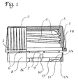
- the main body 1 can be seen in FIG. 1, perpendicularly in the right part of the figure cut, in the left part of the picture in side view with the grip ribs 2.
- the side wall 3 of the main body 1 has one to be closed Container-adapted thread profile 4.
- a seal 5 is inserted in the bottom of the cap.
- the main body 1 is over fine webs 6 that can be torn off when it is opened for the first time and stronger connecting webs 7 with which the originality of the container or Circlip indicating bottle filling 8 connected.
- the profile the locking ring 8 is cut in the lower right part of the picture, but only partially recognizable, since the section, as also in Fig. 2, in the area of a Locking cam 11 runs.
- the circlip points in the upper, near the main body Area a conical to facilitate the demolding downwards expanding profile 8a. Its taper ends at the level of the locking cams 11 formed shoulder 12a.
- the locking ring 8 has cutouts 9, in the area of which the predetermined breaking points 10 lie.
- the design of the locking cam 11 takes one the bottom right part of Fig. 1, and then 2 and 3.
- the shoulder 12a preferably runs at about 90 Degree, the ideal value for an effective grip under the lower edge of the container mouth and "locking" or early blasting of the locking ring 8 when opening the screw cap for the first time.
- the slope 12b on the underside of the locking cam facing away from the cap bottom 11 facilitates the mechanical application of the closure cap.
- the design the shoulder 12a and the bevel 12b including the circumferential or Direction of rotation extending outlet contour 13 of the locking cam shown 11 one takes out the one drawn to the left of the cut part of the picture Edges, as well as Fig. 3.
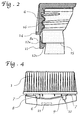
- Fig. 2 is a longitudinal section through part of an applied to a bottle Bottle screw cap shown and again in the area a locking cam 11.
- the reference numerals correspond to those in the Fig. 1 and the following Fig.
- the profile the closure cap including the locking ring 8 with slope 12b is selected that their application under the usual conditions (screwing or pressing on middle. Room temperature) without any problems resetting, intermediate elastic spreading of the circlip 8 takes place, the connecting webs 6 and 7 temporarily hinge-like move something outwards. Snap in after the cap is in place the locking cam 11 in the locking or locking position below the lower edge 15 or the projection of the container or bottle mouth one as shown.
- Fig. 3 shows a plan view of a complete, from the main body for reasons of illustration detached circlip 8. It has several fine webs 6, two connecting webs 7, two conical indentations 8b, two predetermined breaking points 10 and two locking cams 11.
- the profiles of the aforementioned Elements are clearly visible here, including those necessary for demoulding the same-shaped outlet contours 10a and 13 of the predetermined breaking points 10 and the locking cam 11. Likewise, the one described above is below Protected positioning of the elements to one another is recognizable.
- Fig. 4 shows a bottle cap with the locking ring shown in Fig. 3 8 shortly before tearing open.
- the screw cap has when turning it up (for the first time), the position is slightly exceeded the two locking cams 11 with their shoulder 12a on the (not shown) Bottom edge 15 of the bottle or container mouth to lie on come. Accordingly, the two have each approximately in the middle between the locking webs located locking cams 11 the locking ring 8 away from the main body 1 in the sense of a triangle of forces 7-11-7 pulled by tearing off some fine webs 6.
- the deformation of the Ring 8 also applies to the hidden rear half of the locking ring 8.
- at least one predetermined breaking point 10 tears as a result of the increased Tensile forces in the circumferential direction of the locking ring 8 and under the given wedge effect of the aforementioned triangle of forces from the recess 9 outgoing.
- the screw cap is made in one piece and all the parts described are molded onto each other. (An exception concerns the deposit of a separate, possibly required by some users seal made of other material 5). So far the invention Cap made of plastic material by injection molding or embossing is done in one step without post-forming, which is a corresponding design the cap and the injection molding or embossing tool required makes. For the latter, it should be added that for the manufacture and demolding a multi-part tool containing novel elements is required, as shown in the sequence of figures 5a to 5c.
- a preferably as a hollow cylinder designed part, here designated 20, is rotatable and its outer jacket a profile for molding the inner surface of the locking ring 8 including recesses for the contours of the locking cam 11 and other elements (see. 6 u.
- the molded parts are moved or opened 18 and 19 in the axial direction according to FIG. 5b of the rotating hollow cylinder 20 according to the invention in the direction of rotation of the screw cap against that of FIG. 3 apparent, gradually tapering outlet contours 10a and 13 rotated, the locking ring 8 briefly reversibly expanded and then, as indicated in FIG. 5c, the demolding process is completed without any problems.
- the preferred plastic material is based on polyethylene or polypropylene. Depending on customer requirements and application, there are also others Polymers and copolymers can be used.
Description
- Fig. 1
- eine teilweise geschnittene Seitenansicht einer Schraubverschlußkappe;
- Fig. 2
- einen Längsschnitt durch eine auf eine Flasche aufgebrachten Schraubverschlußkappe gem. Fig. 1 im Detail;
- Fig. 3
- eine Draufsicht auf einen vom Hauptkörper abgelösten Sicherungsring mit jeweils zwei Verriegelungsnockenn, Stegen und Sollbruchstellen;
- Fig. 4
- eine Schraubverschlußkappe gem. Fig. 1 im Prozeß der erstmaligen Öffnung, kurz vor dem Aufreißen der unten rechts gezeigten Sollbruch stelle;
- Fig. 5a bis 5c
- die Gestaltung eines Spritzgieß- oder Prägewerkzeuges und die Entformung einer erfindungsgemäßen Verschlußkappe - im Bereich des Sicherungsringes mit Veniegelungsnocke.
Claims (12)
- Schraubverschlußkappe aus Kunststoffmaterial zum Verschließen von Behältern, insbesondere Flaschen mit originalabgefüllten Getränken, deren Mündungsbereich in seiner öffnungsnahen Zone ein Außengewinde (16) aufweist und im öffnungsferneren Bereich mit einer gegenüber dem Durchmesser des direkt anschließenden Halses erweiterten, eine ringförmig umlaufende Unterkante (15) bildenden Zone abschließt, wobei der ein Innengewinde (4) aufweisende Hauptkörper (1) der Schraubverschlußkappe in seinem öffnungsfernen bzw. unteren Bereich einstückig über angeformte Verbindungsstege (7) in einen beim erstmaligen Öffnen aufreißenden Originalitätssicherungsring (8) übergeht, der mehrere Sollbruchstellen (10) sowie mehrere an seinem Umfang verteilte, nach innen weisend angeformte, zwischen den Sollbruchstellen (10) befindliche Ver-riegelungsnocken (11) aufweist, deren Profil eine zur Untergreifung der Unterkante (15) der Behältermündung dienende Abkantung bzw. Schräge (vgl.12a) aufweist, wobeia) die Abkantung (12a) der Verriegelungsnocken (11) als eine zur Mittelachse etwa rechtwinklig verlaufende Schulter bzw. Untergreifungsfläche ausgebildet ist undb) die Verriegelungsnocken (11) zur Erleichterung des Entformungsprozesses entlang der Innenfläche des Sicherungsringes (8) eine einer entformenden Rotationsbewegung gemäße, sich allmählich verjüngende Auslaufkontur (13) aufweisen, die derart ausgebildet ist, daßc) die Entformung des Sicherungsringes im wesentlichen unter einer teilweisen Rotation um die Achse eines die Innenkontur der Verriegelungsnocken (11) formenden Werkzeugteils (vgl. 20) durchführbar ist.
- Schraubverschlußkappe nach Anspruch 1 dadurch gekennzeichnet, daß sowohl die Verriegelungsnocken (11) als auch die Sollbruchstellen (10) zwecks Erleichterung der Entformung entlang der Innenfläche des Sicherungringes gleichsinnige, in Drehrichtung der Schraubkappe sich verjüngende Auslaufkonturen (10a,13) aufweisen.
- Schraubverschlußkappe nach Anspruch 1 oder 2, dadurch gekennzeichnet, daß zwischen jeweils zwei von insgesamt zwei bis vorzugsweise fünf Verbindungsstegen (7) eine Sollbruch-stelle (10) und eine Verriegelungsnocke (11) angeordnet sind, wobei die Sollbruchstelle (10) jeweils in der Nähe eines Verbindungssteges (7), die Verriegelungsnocke (11) dagegen etwa mittig zwischen zwei Stegen (7) angeordnet ist, und/oder daß der Hauptkörper über zuzüglich zu den Verbindungsstegen (7) vorgesehenen Feinstäbe (6) in den Originalitätssicherungsring (8) übergeht und/oder daß die Verriegelungsnocken (11) an der dem Hauptkörper (11) abgewandten Unterseite eine Abkantung bzw. Schräge (12b) zur Erleichterung des Aufbringens des Verschlusses besitzen.
- Schraubverschlußkappe nach einem der vorhergehenden Ansprüche, dadurch gekennzeichnet, daß die annähernd senkrecht bzw. parallel zur Mittelachse verlaufenden Sollbruchstellen (10) im unterhalb einer ihnen zugeordneten hauptkörpernäheren Aussparung (9) des Sicherungsringes (8) verbleibenden Randmaterial desselben angeordnet sind.
- Schraubverschlußkappe nach einem der vorhergehenden Ansprüche, dadurch gekennzeichnet, daß die Untergreifungsfläche (12a) des Verriegelungsnockens (11) zur Mittelachse eine Abweichung vom rechten Winkel bis zu +/- 5 Grad aufweist.
- Schraubverschlußkappe nach einem der vorangehenden Ansprüche, dadurch gekennzeichnet, daß die Verriegelungsnocken (11) in Richtung Mittelachse zwecks Untergreifung etwa 1,0 bis 1,8 mm Tiefe aufweisen und/oder daß die Verriegelungsnocken (11) eine entlang der Innenfläche des Sicherungsringes (8) in Umfangs- bzw. Drehrichtung umlaufende Ausdehnung von etwa 3 bis 10 mm aufweisen und/oder daß die im Gegensatz zu den Verbindungsstegen (7) bezüglich des erstmaligen Öffnens abreißbar gestalteten Feinstege (6) ein dreieckiges Verbindungsprofil aufwiesen, dessen Spitze radial nach innen orientiert ist, wobei die mittlere Material- bzw. Profilstärke etwa 0.4 bis 0,8 mm beträgt.
- Schraubverschlußkappe nach einem der vorangehenden Ansprüche, dadurch gekennzeichnet, daß die Anzahl der Sollbruchstellen (10), Verbindungsstege (7) und Ver-riegelungsnocken (11) gleich groß ist und jeweils zwei bis fünf beträgt.
- Schraubverschlußkappe nach einem der vorangehenden Ansprüche, dadurch gekennzeichnet, daß der Sicherungsring (8) im hauptkörpernahen Bereich ein konisch sich nach unten bzw. zur Unterkante (15) der Flaschenmündung hin erweiterndes Profil (8a) aufweist, während im unteren, hauptkörperfernen Bereich Innen- und Außenfläche des Sicherungsringes (8) etwa parallel verlaufen - ausgenommen im Bereich der Verriegelungsnocken (11).
- Schraubverschlußkappe nach einem der vorangehenden Ansprüche, dadurch gekennzeichnet, daß der Innendurchmesser des Anschlußbereiches des Hauptkörpers (1) an den Sicherungsring (8) einerseits und der Außendurchmesser des Sicherungsringes (8) identisch sind.
- Schraubverschlußkappe nach einem der vorangehenden Ansprüche, gekennzeichnet durch einen ringförmig außen am Anschlußbereich des Hauptkörpers (1) umlaufenden Verstärkungswulst (14).
- Schraubverschlußkappe nach einem der vorangehenden Ansprüche, dadurch gekennzeichnet, daß der Hauptkörper Griffrippen (2) aufweist, deren abgerundete Rücken sich zum unteren Rand bzw. Verstärkungswulst (14) hin verbreitert.
- Verfahren zur Herstellung einer Schraubverschlußkappe aus Kunststoffmaterial zum Verschließen von Behältern, insbesondere für Flaschen mit originalabgefüllten Getränken, deren Mündungsbereich in seiner öffnungsnahen Zone ein Außengewinde (16) aufweist und im öffnungsferneren Bereich mit einer gegenüber dem Durchmesser des direkt anschließenden Halses erweiterten, eine ringförmig umlaufende Unterkante (15) bildenden Zone abschließt, wobei der ein Innengewinde (4) aufweisende Hauptkörper (1) der Schraubverschlußkappe in seinem öffnungsfernen bzw. unteren Bereich einstückig über mindestens zwei angeformte Verbindungsstege (7) in einen beim erstmaligen Öffnen aufreißenden Originalitätssicherungsring (8) übergeht, der mindestens zwei Sollbruchstellen (10) sowie mindestens zwei an seinem Umfang verteilte, nach innen weisend angeformte, zwischen den Sollbruchstellen (10) befindliche Verriegelungsnocken (11) aufweist, deren Schulter bzw. Untergreifungsfläche (12a) zur Mittelachse einen rechten Winkel mit einer Abweichung von max. +/- 5 Grad aufweist, insbesondere nach einem der vorstehenden Ansprüchen 1 bis 11, dadurch gekennzeichnet, daß die Herstellung im Spritzgieß- oder Prägeverfahren erfolgt unter Verwendung von Kunststoffmaterial auf Basis von Polyäthylen oder Polypropylen und mit einem Werkzeug, das neben einem Formkern und herkömmlichen, eine monodirektionale Form-Öffnungs-Bewegung in axialer Richtung ausführenden Werkzeugteilen (18,19) ein um die Achse rotierbar und parallel zur Achse verschiebbares, bevorzugt als Dreh-Hohlzylinder (20) ausgebildetes Formteil besitzt, dessen Außenmantel ein Profil zur Ausformung von Ausnehmungen für die Konturen der Verriegelungsnocken (11) und der Sollbruchstellen (10) aufweist sowie einen solchen Außendurchmesser in Relation zum Formkern (17), daß der Sicherungsring (8) mittels einer Drehbewegung des Formteils (20) unter kurzzeitiger elastischer Ausweitung entformt werden kann, wonach mittels einer axial verlaufenden Abstreifbewegung der Sicherungsring (8) über die Außenkante (17a) des Formkerns (17) geschoben und die komplette Schraubverschlußkappe somit von dem Werkzeug abgestreift wird.
Applications Claiming Priority (2)
| Application Number | Priority Date | Filing Date | Title |
|---|---|---|---|
| DE19613364 | 1996-04-03 | ||
| DE19613364A DE19613364C1 (de) | 1996-04-03 | 1996-04-03 | Schraubverschlußkappe aus Kunststoff und Verfahren zu deren Herstellung |
Publications (2)
| Publication Number | Publication Date |
|---|---|
| EP0799772A1 EP0799772A1 (de) | 1997-10-08 |
| EP0799772B1 true EP0799772B1 (de) | 2000-05-24 |
Family
ID=7790393
Family Applications (1)
| Application Number | Title | Priority Date | Filing Date |
|---|---|---|---|
| EP97105194A Expired - Lifetime EP0799772B1 (de) | 1996-04-03 | 1997-03-27 | Schraubverschlusskappe aus Kunststoff und Verfahren zu deren Herstellung |
Country Status (3)
| Country | Link |
|---|---|
| EP (1) | EP0799772B1 (de) |
| DE (2) | DE19613364C1 (de) |
| ES (1) | ES2150163T3 (de) |
Families Citing this family (10)
| Publication number | Priority date | Publication date | Assignee | Title |
|---|---|---|---|---|
| IT247417Y1 (it) * | 1999-01-05 | 2002-08-22 | Sacmi | Capsula a vite con guarnizione riportata . |
| FR2821829B1 (fr) * | 2001-03-08 | 2003-11-21 | Tetra Laval Holding Et Finance | Dispositif de bouchage, col compatible avec ce dispositif et recipient comprenant un tel col bouche par un tel dispositif |
| US6877624B2 (en) * | 2002-01-02 | 2005-04-12 | Erie County Plastics | Method of injection molding closure with continuous internal rigid rib, closure made thereby having a lead-in structure and mold for forming same |
| CN101100229A (zh) * | 2007-08-28 | 2008-01-09 | 北京万江科技有限公司 | 一种设有两道密封环的吹塑瓶螺纹盖 |
| EP2179942B1 (de) * | 2008-10-24 | 2014-12-10 | Clariant Production (France) S.A.S. | Schraubverschluss, Behälterkörper und Behälter |
| DE102009044643A1 (de) | 2009-11-24 | 2011-05-26 | Kunststofftechnik Waidhofen An Der Thaya Gmbh | Verschlusskappe mit Garantiering sowie Spritzgießwerkzeug und Verfahren zu deren Herstellung |
| JP5291175B2 (ja) * | 2011-12-16 | 2013-09-18 | 日本クロージャー株式会社 | 合成樹脂製容器蓋及びこれと容器との組み合わせ |
| ES2587691T3 (es) | 2014-03-25 | 2016-10-26 | S.A. Vichy Catalàn | Dispositivo protector para envases |
| CN107415174B (zh) * | 2015-03-04 | 2019-10-25 | 台州市薇薇安工贸有限公司 | 一种深牙内螺纹脱模机构注塑模具及其使用方法 |
| US20220177199A1 (en) * | 2020-12-04 | 2022-06-09 | Niagara Bottling, Llc | Multiple asymmetric anchor container closure |
Family Cites Families (11)
| Publication number | Priority date | Publication date | Assignee | Title |
|---|---|---|---|---|
| EP0094026B1 (de) * | 1982-05-06 | 1988-08-10 | Anchor Hocking Corporation | Sicherheitsverschluss für Getränke |
| GR850153B (de) * | 1984-02-06 | 1985-03-29 | Obrist Ag Crown | |
| EP0254673B1 (de) * | 1986-07-11 | 1990-04-18 | Interplastic AG | Sicherheitsband an einem Gebindeverschluss |
| CH672109A5 (de) * | 1987-01-30 | 1989-10-31 | Wiedmer Plastikform W | |
| FR2619552B1 (fr) * | 1987-08-18 | 1990-02-02 | Astra Plastique | Bouchon a vis a ceinture d'inviolabilite, du type demoule par devissage, et moule utilise pour la fabrication de ce bouchon |
| GB8720683D0 (en) * | 1987-09-03 | 1987-10-07 | Metal Closures Ltd | Closures for containers |
| DE4121618A1 (de) * | 1991-06-29 | 1993-01-14 | Alcoa Gmbh Verpackwerke | Kunststoff-verschluss fuer behaelter |
| DE4121619C2 (de) * | 1991-06-29 | 1995-04-27 | Alcoa Gmbh Verpackwerke | Kunststoff-Verschluß für Behälter |
| CA2107041A1 (en) * | 1993-02-09 | 1994-08-10 | Jose Carvalheiro | Stopper device for recipient |
| ES1028707U (es) * | 1993-09-03 | 1995-03-01 | Novembal Sa | Tapon de rosca con anillo de inviolabilidad. |
| CH688036A5 (de) * | 1994-06-23 | 1997-04-30 | Crown Cork Ag | Garantieverschluss und Verfahren zu seiner Herstellung. |
-
1996
- 1996-04-03 DE DE19613364A patent/DE19613364C1/de not_active Expired - Fee Related
-
1997
- 1997-03-27 DE DE59701743T patent/DE59701743D1/de not_active Expired - Fee Related
- 1997-03-27 EP EP97105194A patent/EP0799772B1/de not_active Expired - Lifetime
- 1997-03-27 ES ES97105194T patent/ES2150163T3/es not_active Expired - Lifetime
Also Published As
| Publication number | Publication date |
|---|---|
| DE59701743D1 (de) | 2000-06-29 |
| EP0799772A1 (de) | 1997-10-08 |
| DE19613364C1 (de) | 1997-11-20 |
| ES2150163T3 (es) | 2000-11-16 |
Similar Documents
| Publication | Publication Date | Title |
|---|---|---|
| DE69935897T2 (de) | Sicherheitsverschluss für Behälter und Herstellungverfahren | |
| EP0737156B1 (de) | Kunststoff-schnappverschluss mit garantiesicherung und verfahren zu dessen herstellung | |
| DE2703404A1 (de) | Schraubverschlusskapsel aus kunststoffmaterial und form zu ihrer herstellung | |
| EP0593396A1 (de) | Garantieverschluss aus Kunststoff | |
| EP0916587A1 (de) | Garantieverschluss | |
| WO2007031162A1 (de) | Garantieschraubverschluss für behälter und flaschen, insbesondere für kunststoffflaschen | |
| DE2063865A1 (de) | Zusammengesetzter Deckel für Behälter | |
| EP0799772B1 (de) | Schraubverschlusskappe aus Kunststoff und Verfahren zu deren Herstellung | |
| EP0786417A2 (de) | Kunststofftube mit einem Tubenkörper, sowie Verfahren zu deren Herstellung | |
| EP0951428B1 (de) | Flaschen-schraubverschluss aus kunststoff mit garantieband | |
| DE1942312C3 (de) | Durch axiales Aufpressen auf den Hals einer Flasche aufbringbare Verschlußkappe | |
| DE2315962A1 (de) | Verschlusskappenrohling fuer flaschen od. dgl. | |
| EP0098810A2 (de) | Verschlusskappe, insbesondere Garantie-Verschlusskappe für Flaschen | |
| WO2012017011A1 (de) | Schraubverschluss mit flexband | |
| DE2233305A1 (de) | Schraubverschluss mit originalitaetssicherungsring | |
| EP0270621B1 (de) | Garantieverschluss | |
| WO1998015465A1 (de) | Schraubverschluss mit einem sicherheits- und garantieband | |
| DE19712364A1 (de) | Schnappverschluß | |
| WO2002036451A1 (de) | Schraubkappe mit garantieband | |
| EP0886606B1 (de) | Behältermündung und verschlusskappe | |
| EP0387302B1 (de) | Originalitätsverschluss | |
| DE4305138A1 (en) | Safety closure for bottles etc.with cap and safety ring with break line - has recesses between sectors formed around flanged lower edge of safety ring | |
| EP1529005B1 (de) | Verschluss/ausgiess-kombination mit originalit tssicherung | |
| EP1638854B1 (de) | Verschliesssystem und verfahren zum verschliessen von behältern | |
| WO2019197214A1 (de) | Fälschungssicherer schraubverschluss |
Legal Events
| Date | Code | Title | Description |
|---|---|---|---|
| PUAI | Public reference made under article 153(3) epc to a published international application that has entered the european phase |
Free format text: ORIGINAL CODE: 0009012 |
|
| AK | Designated contracting states |
Kind code of ref document: A1 Designated state(s): CH DE ES FR GB IT LI |
|
| 17P | Request for examination filed |
Effective date: 19971219 |
|
| 17Q | First examination report despatched |
Effective date: 19981217 |
|
| GRAG | Despatch of communication of intention to grant |
Free format text: ORIGINAL CODE: EPIDOS AGRA |
|
| GRAG | Despatch of communication of intention to grant |
Free format text: ORIGINAL CODE: EPIDOS AGRA |
|
| GRAH | Despatch of communication of intention to grant a patent |
Free format text: ORIGINAL CODE: EPIDOS IGRA |
|
| GRAH | Despatch of communication of intention to grant a patent |
Free format text: ORIGINAL CODE: EPIDOS IGRA |
|
| GRAA | (expected) grant |
Free format text: ORIGINAL CODE: 0009210 |
|
| AK | Designated contracting states |
Kind code of ref document: B1 Designated state(s): CH DE ES FR GB IT LI |
|
| PG25 | Lapsed in a contracting state [announced via postgrant information from national office to epo] |
Ref country code: IT Free format text: LAPSE BECAUSE OF FAILURE TO SUBMIT A TRANSLATION OF THE DESCRIPTION OR TO PAY THE FEE WITHIN THE PRESCRIBED TIME-LIMIT;WARNING: LAPSES OF ITALIAN PATENTS WITH EFFECTIVE DATE BEFORE 2007 MAY HAVE OCCURRED AT ANY TIME BEFORE 2007. THE CORRECT EFFECTIVE DATE MAY BE DIFFERENT FROM THE ONE RECORDED. Effective date: 20000524 |
|
| REG | Reference to a national code |
Ref country code: CH Ref legal event code: EP |
|
| REF | Corresponds to: |
Ref document number: 59701743 Country of ref document: DE Date of ref document: 20000629 |
|
| REG | Reference to a national code |
Ref country code: CH Ref legal event code: NV Representative=s name: R. A. EGLI & CO. PATENTANWAELTE |
|
| GBT | Gb: translation of ep patent filed (gb section 77(6)(a)/1977) |
Effective date: 20000927 |
|
| EN | Fr: translation not filed | ||
| REG | Reference to a national code |
Ref country code: ES Ref legal event code: FG2A Ref document number: 2150163 Country of ref document: ES Kind code of ref document: T3 |
|
| REG | Reference to a national code |
Ref country code: FR Ref legal event code: RN |
|
| ET | Fr: translation filed | ||
| REG | Reference to a national code |
Ref country code: FR Ref legal event code: FC |
|
| PLBE | No opposition filed within time limit |
Free format text: ORIGINAL CODE: 0009261 |
|
| STAA | Information on the status of an ep patent application or granted ep patent |
Free format text: STATUS: NO OPPOSITION FILED WITHIN TIME LIMIT |
|
| 26N | No opposition filed | ||
| REG | Reference to a national code |
Ref country code: GB Ref legal event code: IF02 |
|
| PGFP | Annual fee paid to national office [announced via postgrant information from national office to epo] |
Ref country code: GB Payment date: 20030325 Year of fee payment: 7 |
|
| PGFP | Annual fee paid to national office [announced via postgrant information from national office to epo] |
Ref country code: FR Payment date: 20030331 Year of fee payment: 7 Ref country code: ES Payment date: 20030331 Year of fee payment: 7 |
|
| PGFP | Annual fee paid to national office [announced via postgrant information from national office to epo] |
Ref country code: CH Payment date: 20030626 Year of fee payment: 7 |
|
| PGFP | Annual fee paid to national office [announced via postgrant information from national office to epo] |
Ref country code: DE Payment date: 20040310 Year of fee payment: 8 |
|
| PG25 | Lapsed in a contracting state [announced via postgrant information from national office to epo] |
Ref country code: GB Free format text: LAPSE BECAUSE OF NON-PAYMENT OF DUE FEES Effective date: 20040327 |
|
| PG25 | Lapsed in a contracting state [announced via postgrant information from national office to epo] |
Ref country code: ES Free format text: LAPSE BECAUSE OF NON-PAYMENT OF DUE FEES Effective date: 20040329 |
|
| PG25 | Lapsed in a contracting state [announced via postgrant information from national office to epo] |
Ref country code: LI Free format text: LAPSE BECAUSE OF NON-PAYMENT OF DUE FEES Effective date: 20040331 Ref country code: CH Free format text: LAPSE BECAUSE OF NON-PAYMENT OF DUE FEES Effective date: 20040331 |
|
| REG | Reference to a national code |
Ref country code: CH Ref legal event code: PL |
|
| GBPC | Gb: european patent ceased through non-payment of renewal fee |
Effective date: 20040327 |
|
| PG25 | Lapsed in a contracting state [announced via postgrant information from national office to epo] |
Ref country code: FR Free format text: LAPSE BECAUSE OF NON-PAYMENT OF DUE FEES Effective date: 20041130 |
|
| REG | Reference to a national code |
Ref country code: FR Ref legal event code: ST |
|
| REG | Reference to a national code |
Ref country code: ES Ref legal event code: FD2A Effective date: 20040329 |
|
| PG25 | Lapsed in a contracting state [announced via postgrant information from national office to epo] |
Ref country code: DE Free format text: LAPSE BECAUSE OF NON-PAYMENT OF DUE FEES Effective date: 20051001 |