EP0799772B1 - Plastic screw cap and method for manufacturing the same - Google Patents
Plastic screw cap and method for manufacturing the same Download PDFInfo
- Publication number
- EP0799772B1 EP0799772B1 EP97105194A EP97105194A EP0799772B1 EP 0799772 B1 EP0799772 B1 EP 0799772B1 EP 97105194 A EP97105194 A EP 97105194A EP 97105194 A EP97105194 A EP 97105194A EP 0799772 B1 EP0799772 B1 EP 0799772B1
- Authority
- EP
- European Patent Office
- Prior art keywords
- screw cap
- locking ring
- design
- set forth
- main body
- Prior art date
- Legal status (The legal status is an assumption and is not a legal conclusion. Google has not performed a legal analysis and makes no representation as to the accuracy of the status listed.)
- Expired - Lifetime
Links
Images


Classifications
-
- B—PERFORMING OPERATIONS; TRANSPORTING
- B65—CONVEYING; PACKING; STORING; HANDLING THIN OR FILAMENTARY MATERIAL
- B65D—CONTAINERS FOR STORAGE OR TRANSPORT OF ARTICLES OR MATERIALS, e.g. BAGS, BARRELS, BOTTLES, BOXES, CANS, CARTONS, CRATES, DRUMS, JARS, TANKS, HOPPERS, FORWARDING CONTAINERS; ACCESSORIES, CLOSURES, OR FITTINGS THEREFOR; PACKAGING ELEMENTS; PACKAGES
- B65D41/00—Caps, e.g. crown caps or crown seals, i.e. members having parts arranged for engagement with the external periphery of a neck or wall defining a pouring opening or discharge aperture; Protective cap-like covers for closure members, e.g. decorative covers of metal foil or paper
- B65D41/32—Caps or cap-like covers with lines of weakness, tearing-strips, tags, or like opening or removal devices, e.g. to facilitate formation of pouring openings
- B65D41/34—Threaded or like caps or cap-like covers provided with tamper elements formed in, or attached to, the closure skirt
- B65D41/3442—Threaded or like caps or cap-like covers provided with tamper elements formed in, or attached to, the closure skirt with rigid bead or projections formed on the tamper element and coacting with bead or projections on the container
- B65D41/3447—Threaded or like caps or cap-like covers provided with tamper elements formed in, or attached to, the closure skirt with rigid bead or projections formed on the tamper element and coacting with bead or projections on the container the tamper element being integrally connected to the closure by means of bridges
-
- B—PERFORMING OPERATIONS; TRANSPORTING
- B29—WORKING OF PLASTICS; WORKING OF SUBSTANCES IN A PLASTIC STATE IN GENERAL
- B29C—SHAPING OR JOINING OF PLASTICS; SHAPING OF MATERIAL IN A PLASTIC STATE, NOT OTHERWISE PROVIDED FOR; AFTER-TREATMENT OF THE SHAPED PRODUCTS, e.g. REPAIRING
- B29C43/00—Compression moulding, i.e. applying external pressure to flow the moulding material; Apparatus therefor
- B29C43/32—Component parts, details or accessories; Auxiliary operations
- B29C43/36—Moulds for making articles of definite length, i.e. discrete articles
- B29C43/42—Moulds for making articles of definite length, i.e. discrete articles for undercut articles
-
- B—PERFORMING OPERATIONS; TRANSPORTING
- B29—WORKING OF PLASTICS; WORKING OF SUBSTANCES IN A PLASTIC STATE IN GENERAL
- B29C—SHAPING OR JOINING OF PLASTICS; SHAPING OF MATERIAL IN A PLASTIC STATE, NOT OTHERWISE PROVIDED FOR; AFTER-TREATMENT OF THE SHAPED PRODUCTS, e.g. REPAIRING
- B29C45/00—Injection moulding, i.e. forcing the required volume of moulding material through a nozzle into a closed mould; Apparatus therefor
- B29C45/17—Component parts, details or accessories; Auxiliary operations
- B29C45/40—Removing or ejecting moulded articles
- B29C45/44—Removing or ejecting moulded articles for undercut articles
- B29C45/4407—Removing or ejecting moulded articles for undercut articles by flexible movement of undercut portions of the articles
-
- B—PERFORMING OPERATIONS; TRANSPORTING
- B29—WORKING OF PLASTICS; WORKING OF SUBSTANCES IN A PLASTIC STATE IN GENERAL
- B29L—INDEXING SCHEME ASSOCIATED WITH SUBCLASS B29C, RELATING TO PARTICULAR ARTICLES
- B29L2001/00—Articles provided with screw threads
-
- B—PERFORMING OPERATIONS; TRANSPORTING
- B29—WORKING OF PLASTICS; WORKING OF SUBSTANCES IN A PLASTIC STATE IN GENERAL
- B29L—INDEXING SCHEME ASSOCIATED WITH SUBCLASS B29C, RELATING TO PARTICULAR ARTICLES
- B29L2031/00—Other particular articles
- B29L2031/56—Stoppers or lids for bottles, jars, or the like, e.g. closures
- B29L2031/565—Stoppers or lids for bottles, jars, or the like, e.g. closures for containers
-
- B—PERFORMING OPERATIONS; TRANSPORTING
- B65—CONVEYING; PACKING; STORING; HANDLING THIN OR FILAMENTARY MATERIAL
- B65D—CONTAINERS FOR STORAGE OR TRANSPORT OF ARTICLES OR MATERIALS, e.g. BAGS, BARRELS, BOTTLES, BOXES, CANS, CARTONS, CRATES, DRUMS, JARS, TANKS, HOPPERS, FORWARDING CONTAINERS; ACCESSORIES, CLOSURES, OR FITTINGS THEREFOR; PACKAGING ELEMENTS; PACKAGES
- B65D2401/00—Tamper-indicating means
- B65D2401/15—Tearable part of the closure
- B65D2401/30—Tamper-ring remaining connected to closure after initial removal
-
- B—PERFORMING OPERATIONS; TRANSPORTING
- B65—CONVEYING; PACKING; STORING; HANDLING THIN OR FILAMENTARY MATERIAL
- B65D—CONTAINERS FOR STORAGE OR TRANSPORT OF ARTICLES OR MATERIALS, e.g. BAGS, BARRELS, BOTTLES, BOXES, CANS, CARTONS, CRATES, DRUMS, JARS, TANKS, HOPPERS, FORWARDING CONTAINERS; ACCESSORIES, CLOSURES, OR FITTINGS THEREFOR; PACKAGING ELEMENTS; PACKAGES
- B65D2401/00—Tamper-indicating means
- B65D2401/15—Tearable part of the closure
- B65D2401/35—Vertical or axial lines of weakness
Definitions
- the invention relates to screw caps made of plastic material for Closing containers, especially bottles with originally filled Beverages, and a method for producing such screw caps.
- Bottle screw caps are from the German patent DE 41 21 619 C2 became known.
- the disadvantage here is the fact that there a fully effective grip under the bottom edge of the bottle mouth was realized.
- the projections are designed as movable flags. But without one there is a risk of exact positioning after application of the cap Malfunction. To limit this, these flags became evident here elaborately designed and provided in large numbers.
- the first step will be the engagement elements parallel to the central axis or the demolding axis molded and would then have to be in a separate post-forming process be brought into their effective inward position. Before using the skilled person rejects this expensive process.
- the object of the present invention is to overcome the aforementioned disadvantages of To overcome the state of the art and to create a screw cap, on the one hand, a fully effective grip under the bottom edge of the bottle mouth ensures that an imperceptible opening of the container or a manipulation of the original filling, especially with drinks, is excluded.
- Such locking cams should be designed be in a one-step manufacturing process without subsequent further deformation processes can be produced and continue to be both with regard to the demoulding, as well as the machine application process and the manufacturing costs incurred are optimally designed.
- the features of the first part of claim 3 are to be understood to mean that in the presence of total a total of two, usually opposite, connecting bridges there are two locking cams, one locking cam each approximately in the middle between two connecting bars. Likewise are two predetermined breaking points that are also approximately opposite each other on the ring circumference available, which are located near one of the two connecting bridges. This configuration ensures that when the container is opened an approximately symmetrical triangle of forces between the web and the locking cam web is created, the one early wedge or Explosive effect on the predetermined breaking point without the need for greater forces are.
- the reliability and effectiveness of the locking cams in contrast about flags u. the like is caused by the staring along its base Forming on the outer surface of the circlip and its approximately rectangular to the center axis of the cap and bottle or container thread Lower edge of the area under the container or bottle mouth Shoulder is also guaranteed.
- the locking cams have preferred in adaptation to the lower edge of the container closure zone a deviation of +/- 5 degrees from the right angle to the central axis on.
- the dimensionally stable design of the Cam profile an immediate reliable bursting of the locking ring in the first attempt at opening, in contrast to such known locking elements, the deformations during the manufacturing and / or application process and possibly subject to provisions, with many of the known bottle caps good results only in the case of narrow geometric tolerances Cap and container mouth as well as the material properties of the used Plastics (elongation, tensile strength - depending on the Process temperatures, etc.).
- Another preferred feature of the screw cap is that known attachment of the fine webs.
- preferred and their shape with a triangular connection profile is new.
- a material thickness of 0.4 to 0.8 mm is also preferred.
- Such fine bridges enable an optimal stabilization of the circlip or entire cap during manufacturing, demolding, storage, transportation and Application to the closure.
- the number of predetermined breaking points, connecting bars and locking cams according to a further preferred embodiment of the invention to ensure proper tearing of the circlip be great. With four or five elements there is breaking up and deformation the circlip more evenly and visually as well as handling with frequent reuse of the cap after the first opening more appealing than just two elements at a time. In all preferred However, cases are the deformation of the tamper-evident circlip striking, which is radially blown up in at least two places and with formation a jagged line only connected to the main body at certain points is.
- the invention also relates to a method for Manufacture of screw caps of the aforementioned type, i.e. Caps made of plastic material for closing containers, in particular of Bottles with original bottled drinks, according to the preamble of the claim 12th
- the main feature of this process invention is that parallel to Upstream axis movement, as a partial rotation around the central axis of the closure cap and tool rotary movement of a Hollow rotary cylinder.
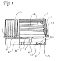
- the main body 1 can be seen in FIG. 1, perpendicularly in the right part of the figure cut, in the left part of the picture in side view with the grip ribs 2.
- the side wall 3 of the main body 1 has one to be closed Container-adapted thread profile 4.
- a seal 5 is inserted in the bottom of the cap.
- the main body 1 is over fine webs 6 that can be torn off when it is opened for the first time and stronger connecting webs 7 with which the originality of the container or Circlip indicating bottle filling 8 connected.
- the profile the locking ring 8 is cut in the lower right part of the picture, but only partially recognizable, since the section, as also in Fig. 2, in the area of a Locking cam 11 runs.
- the circlip points in the upper, near the main body Area a conical to facilitate the demolding downwards expanding profile 8a. Its taper ends at the level of the locking cams 11 formed shoulder 12a.
- the locking ring 8 has cutouts 9, in the area of which the predetermined breaking points 10 lie.
- the design of the locking cam 11 takes one the bottom right part of Fig. 1, and then 2 and 3.
- the shoulder 12a preferably runs at about 90 Degree, the ideal value for an effective grip under the lower edge of the container mouth and "locking" or early blasting of the locking ring 8 when opening the screw cap for the first time.
- the slope 12b on the underside of the locking cam facing away from the cap bottom 11 facilitates the mechanical application of the closure cap.
- the design the shoulder 12a and the bevel 12b including the circumferential or Direction of rotation extending outlet contour 13 of the locking cam shown 11 one takes out the one drawn to the left of the cut part of the picture Edges, as well as Fig. 3.
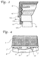
- Fig. 2 is a longitudinal section through part of an applied to a bottle Bottle screw cap shown and again in the area a locking cam 11.
- the reference numerals correspond to those in the Fig. 1 and the following Fig.
- the profile the closure cap including the locking ring 8 with slope 12b is selected that their application under the usual conditions (screwing or pressing on middle. Room temperature) without any problems resetting, intermediate elastic spreading of the circlip 8 takes place, the connecting webs 6 and 7 temporarily hinge-like move something outwards. Snap in after the cap is in place the locking cam 11 in the locking or locking position below the lower edge 15 or the projection of the container or bottle mouth one as shown.
- Fig. 3 shows a plan view of a complete, from the main body for reasons of illustration detached circlip 8. It has several fine webs 6, two connecting webs 7, two conical indentations 8b, two predetermined breaking points 10 and two locking cams 11.
- the profiles of the aforementioned Elements are clearly visible here, including those necessary for demoulding the same-shaped outlet contours 10a and 13 of the predetermined breaking points 10 and the locking cam 11. Likewise, the one described above is below Protected positioning of the elements to one another is recognizable.
- Fig. 4 shows a bottle cap with the locking ring shown in Fig. 3 8 shortly before tearing open.
- the screw cap has when turning it up (for the first time), the position is slightly exceeded the two locking cams 11 with their shoulder 12a on the (not shown) Bottom edge 15 of the bottle or container mouth to lie on come. Accordingly, the two have each approximately in the middle between the locking webs located locking cams 11 the locking ring 8 away from the main body 1 in the sense of a triangle of forces 7-11-7 pulled by tearing off some fine webs 6.
- the deformation of the Ring 8 also applies to the hidden rear half of the locking ring 8.
- at least one predetermined breaking point 10 tears as a result of the increased Tensile forces in the circumferential direction of the locking ring 8 and under the given wedge effect of the aforementioned triangle of forces from the recess 9 outgoing.
- the screw cap is made in one piece and all the parts described are molded onto each other. (An exception concerns the deposit of a separate, possibly required by some users seal made of other material 5). So far the invention Cap made of plastic material by injection molding or embossing is done in one step without post-forming, which is a corresponding design the cap and the injection molding or embossing tool required makes. For the latter, it should be added that for the manufacture and demolding a multi-part tool containing novel elements is required, as shown in the sequence of figures 5a to 5c.
- a preferably as a hollow cylinder designed part, here designated 20, is rotatable and its outer jacket a profile for molding the inner surface of the locking ring 8 including recesses for the contours of the locking cam 11 and other elements (see. 6 u.
- the molded parts are moved or opened 18 and 19 in the axial direction according to FIG. 5b of the rotating hollow cylinder 20 according to the invention in the direction of rotation of the screw cap against that of FIG. 3 apparent, gradually tapering outlet contours 10a and 13 rotated, the locking ring 8 briefly reversibly expanded and then, as indicated in FIG. 5c, the demolding process is completed without any problems.
- the preferred plastic material is based on polyethylene or polypropylene. Depending on customer requirements and application, there are also others Polymers and copolymers can be used.
Description
Die Erfindung betrifft Schraubverschlußkappen aus Kunststoffmaterial zum Verschließen von Behältern, insbesondere von Flaschen mit originalabgefüllten Getränken, sowie ein Verfahren zur Herstellung solcher Schraubverschlußkappen.The invention relates to screw caps made of plastic material for Closing containers, especially bottles with originally filled Beverages, and a method for producing such screw caps.
Flaschenschraubverschlüsse sind aus der deutschen Patentschrift DE 41 21 619 C2 bekanntgeworden. Nachteilig ist hierbei die Tatsache, daß dort eine voll wirksame Untergreifung der Unterkante der Flaschenmündung nicht verwirklicht wurde. Mit Rücksicht auf die bei der Herstellung solcher einstükkiger Verschlußkappen zu beachtenden Entformungsbedingungen wurden nämlich die Vorsprünge als bewegliche Fahnen ausgebildet. Aber ohne eine exakte Positionierung nach Aufbringen der Kappe besteht die Gefahr einer Fehlfunktion. Um diese einzuschränken, wurden diese Fahnen hier offensichtlich aufwendig gestaltet und in größerer Anzahl vorgesehen. Das hat andererseits wieder den Nachteil einer Bremswirkung beim Aufsetzen in den mit sehr hohen Taktgeschwindigkeiten arbeitenden Abfüllmaschinen der Getränkeindustrie und einen Mehrverbrauch von Kunststoffmaterial.Bottle screw caps are from the German patent DE 41 21 619 C2 became known. The disadvantage here is the fact that there a fully effective grip under the bottom edge of the bottle mouth was realized. With regard to the manufacture of such one-piece Sealing caps have to be considered namely the projections are designed as movable flags. But without one there is a risk of exact positioning after application of the cap Malfunction. To limit this, these flags became evident here elaborately designed and provided in large numbers. On the other hand, that has again the disadvantage of a braking effect when touching down with the very high-speed filling machines in the beverage industry and an increased consumption of plastic material.
Im Falle eines Verschlusses gemäß der deutschen Patentschrift DE 41 21 618 C2 gilt eine ähnliche Problematik. Die beim erstmaligen Öffnen als Widerhaken dienenden fahnenartigen Vorsprünge bilden zunächst während des maschinellen Aufschraubens oder Aufpressens der Verschlußkappe mit der Innenfläche des Sicherungsringes einen spitzen Winkel und werden beim Aufbringen nach oben gebogen. Beim Passieren der Unterkante des Flaschenmündungsbereiches sollen dann die unterschiedlich gestalteten und mit Rückstellrippen versehenen Widerhaken oder Fahnen ohne bleibendes Aufdehnen oder gar Aufsprengen des Sicherungsringes in eine stumpfe schräg in Richtung Flaschenöffnung bzw. Unterkante weisende Position gelangen. Dieses Konzept erfordert infolge der komplexen geometrischen Gestaltung ein sehr aufwendiges Werkzeug zur Herstellung solcher Verschlüsse, ohne daß die Erreichung der genannten Ziele gesichert erscheint.In the case of a closure according to German patent DE 41 21 618 C2 has a similar problem. The barbs when opening for the first time serving tab-like projections initially form during the machine Unscrew or press on the cap with the inner surface of the circlip at an acute angle and are when applied bent upwards. When passing the bottom edge of the bottle mouth area then the differently designed and with return ribs provided barbs or flags without permanent expansion or even burst open the circlip in a blunt diagonally towards the bottle opening or lower edge pointing position. This concept requires a very complex due to the complex geometric design Tool for making such closures without reaching of the stated goals appears secure.
Ferner ist aus der europäischen Patentschrift EP 0 254 673 B1 ein Sicherungsring bekannt geworden, der Nocken und Stege in verschiedener Zahl samt einem Einschnitt in den Ring aufweist, der unmittelbar benachbart zu einem Nocken vorgesehen ist, so daß beim Öffnen ein längerer Abschnitt des Ringes von der Kappe wegplatzt und absteht. Dieses auch bei anderen bekannten Ausführungsformen eintretende Ergebnis wird aus funktionalen und ästhetischen Gründen hier nicht angestrebt.Furthermore, a locking ring is known from European patent EP 0 254 673 B1 became known, the cam and webs in different numbers including one Incision in the ring that is immediately adjacent to one Cam is provided so that when opening a longer section of the ring bursts off the cap and protrudes. This also in other known embodiments The result is functional and aesthetic Reasons not sought here.
Auch die aus der europäischen Patentschrift EP 0 154 603 B1 bekanntgewordenen Verriegelungsnocken erfüllen diese Absichten nicht. Nachteilig ist insbesondere die Tatsache, daß dort wiederum eine voll wirksame Untergreifung der Unterkante der Flaschenmündung nicht verwirklicht wurde mit Rücksicht auf die bei der Herstellung solcher einstückiger Verchlußkappen zu beachtenden und in dieser Schrift auch angesprochenen Entformungsbedingungen, wonach die Schulter des Nockenprofils mit der Mittelachse einen Winkel von nicht mehr als 75 bis 85 Grad einnehmen sollte. Das ist schon sehr hoch gegriffen und bedeutet jedenfalls, daß die im Gegensatz zu Fahnen starr angeformten Verriegelungsnocken eine schräg nach unten statt rechtwinklig zur Mittelachse weisende Untergreifungsschulter aufweisen müssen. Those known from European Patent EP 0 154 603 B1 Locking cams do not fulfill these intentions. A particular disadvantage is the fact that there is again a fully effective underpinning the bottom edge of the bottle mouth was not realized with due regard on those to be observed when manufacturing such one-piece caps and in this document also mentioned demolding conditions, according to which the shoulder of the cam profile with the central axis at an angle of should not be more than 75 to 85 degrees. That is very high and in any case means that, unlike flags, they are rigidly molded Locking cams angled down instead of perpendicular to The central axis must have an underlap shoulder.
Sofern man diese Untergreifung verbessern wollte, ist hierzu die Verwendung eines formstabilen Verriegelungsnockens mit einer geeigneten Schulter bzw. Untergreifungsfläche mit annähernd rechtwinkligem Verlauf erwünscht. Tatsächlich scheint ein solcher rechtwinkliger Verlauf schon einmal vorgeschlagen worden zu sein, und zwar in der PCT-Offenlegungsschrift WO 88/05754, Fig. 1. Dieser Vermutung stehen aber massive Einwände entgegen. Zunächst wird dort ausdrücklich und zutreffend darauf verwiesen, daß die dort Oberseite genannte Untergreifungskante in der Regel 50-60 Grad (zur Mittelachse) aufweist. Die obere Grenze entspricht etwa dem gezeichneten Beispiel der vorgenannten EP-Patentschrift. Diese PCT-Schrift beschäftigt sich nun nicht mit den Problemen der Untergreifung und der Entformung, sondern allein mit der schon bezüglich Fahnen erwähnten Stauproblematik beim maschinellen Aufbringen bzw. Aufpressen der Kappen, was maßgeblich von der Gestaltung der Unterkante abhängt. Vollends unglaubwürdig wird der Vorschlag von 90 Grad etc. angesichts des weiten Hineinragens des gezeichneten Nockenprofils in die Nähe der Mittelachse. Ein solches Nockenprofil läßt sich, wenn überhaupt, im Gegensatz zu den dortigen Behauptungen nur mit einer ganz erheblichen und somit untragbaren Verteuerung des Herstellungs- und Entformungsverfahrens realisieren. Und schließlich ist das maschinelle Aufbringen von Verschlußkappen mit dem gezeichneten, weit vorspringenden Nockenprofil absolut utopisch, schon weil der Sicherungsring wegen Überdehnung reißen würde. Der Fachmann wird also diesen Vorschlag nicht aufgreifen und bei abgeschrägten Schultern bleiben, etwa bei den genannten 60 Grad.If you wanted to improve this undergrowth, use it a dimensionally stable locking cam with a suitable shoulder or Reaching surface with an almost rectangular shape is desirable. Indeed Such a right-angled course seems to have been suggested before to have been, namely in the PCT publication WO 88/05754, Fig. 1. This assumption is opposed to massive objections. First is there expressly and correctly pointed out that the top there mentioned underlap edge usually 50-60 degrees (to the central axis). The upper limit corresponds approximately to the drawn example of the aforementioned EP patent. This PCT document is not concerned with the Problems of grip and demolding, but only with the already mentioned with regard to flags jamming problem during machine application or pressing on the caps, which is largely dependent on the design of the Bottom edge depends. The proposal of 90 degrees is completely unbelievable etc. in view of the wide protrusion of the drawn cam profile in the Near the central axis. Such a cam profile can, if at all, in Contrary to the claims there with only a very substantial and thus prohibitively expensive increase in the manufacturing and demolding process realize. And finally there is the mechanical application of sealing caps with the drawn, protruding cam profile absolutely utopian, if only because the circlip would tear due to overstretching. The A specialist will therefore not take up this proposal and in the case of beveled ones Shoulders stay around the above 60 degrees.
Soweit man bisher überhaupt 90 Grad realisiert haben sollte, benötigte man hierfür zwei voneinander getrennte Fertigungsschritte. Im ersten Schritt werden die Hintergreifungselemente parallel zur Mittelachse bzw. Entformungsachse angeformt und müßten dann in einem gesonderten Nachformungsprozeß in ihre wirksame nach innen weisende Position gebracht werden. Vor der Anwendung diese teuren Prozesses weicht der Fachmann zurück. As far as one should have realized 90 degrees so far, one needed for this two separate manufacturing steps. The first step will be the engagement elements parallel to the central axis or the demolding axis molded and would then have to be in a separate post-forming process be brought into their effective inward position. Before using the skilled person rejects this expensive process.
Aufgabe der vorliegenden Erfindung ist es, die vorgenannten Nachteile des Standes der Technik zu überwinden und eine Schraubverschlußkappe zu schaffen, die einerseits eine voll wirksame Untergreifung der Unterkante der Flaschenmündung gewährleistet, so daß ein nicht bemerkbares Öffnen des Behälters bzw. eine Manipulation der Originalabfüllung, insbes. auch bei Getränken, ausgeschlossen ist. Dabei sollten solche Verriegelungsnocken konzipiert werden, die in einem einstufigen Herstellungsprozeß ohne anschließende weitere Verformungsprozesse hergestellt werden können und weiterhin sowohl bezüglich des Entformungs-, als auch des maschinellen Aufbringungsprozesses sowie der anfallenden Herstellungskosten optimal gestaltet sind.The object of the present invention is to overcome the aforementioned disadvantages of To overcome the state of the art and to create a screw cap, on the one hand, a fully effective grip under the bottom edge of the bottle mouth ensures that an imperceptible opening of the container or a manipulation of the original filling, especially with drinks, is excluded. Such locking cams should be designed be in a one-step manufacturing process without subsequent further deformation processes can be produced and continue to be both with regard to the demoulding, as well as the machine application process and the manufacturing costs incurred are optimally designed.
Die Lösung der vorgenannten Aufgabe erfolgt mit Hilfe einer Schraubverschlußkappe,
welche die in Anspruch 1 genannten Merkmale aufweist. Sie bedurfte
angesichts der obengeschilderten Problematik vor ihrer Realisierung
aufwendiger Überlegungen und langwieriger Versuche.The above object is achieved with the aid of a screw cap,
which has the features mentioned in
Merkmale der Erfindung und einiger Ausführungsformen sollen zunäschst noch näher erläutert werden wie folgt:Features of the invention and some embodiments will first be explained in more detail as follows:
Die Merkmale des ersten Teils von Anspruch 3 sind dahingehend zu verstehen, daß bei Vorhandensein von insgesamt zwei, sich normalerweise gegenüberliegenden Verbindungsstegen insgesamt zwei Verriegelungsnocken vorhanden sind, und zwar jeweils eine Verriegelungsnocke etwa mittig zwischen zwei Verbindungsstegen. Ebenso sind zwei sich am Ringumfang ebenfalls etwa gegenüberliegende Sollbruchstellen vorhanden, die sich jeweils in Nähe eines der beiden Verbindungsstege befinden. Mit dieser Konfiguration wird erreicht, daß beim Öffnen des Behälters ein etwa symmetrisches Kräftedreieck Steg-Verriegelungsnocken-Steg entsteht, das eine in Bezug auf den Öffnungsvorgang frühzeitige Keil- bzw. Sprengwirkung auf die Sollbruchstelle ausübt, ohne daß größere Kräfte notwendig sind. Entsprechend kommt es beim Öffnen der Verschlußkappe zu zwei Rissen im Sicherungsring und damit zu zwei etwa gleich langen und umfangssymmetrisch entstehenden Abrißstreifen, die an den beiden Verbindungsstegen noch mit dem Hauptkörper der Verschlußkappe verbunden sind. Im Falle von drei Verbindungsstegen sind drei zwischen ihnen liegende Verriegelungsnocken und drei jeweils gleichsinnig nahe den 3 Stegen angeordnete Sollbruchstellen vorhanden, womit beim Öffnen drei etwa gleich lange Abrißstreifen entstehen usw..The features of the first part of claim 3 are to be understood to mean that in the presence of total a total of two, usually opposite, connecting bridges there are two locking cams, one locking cam each approximately in the middle between two connecting bars. Likewise are two predetermined breaking points that are also approximately opposite each other on the ring circumference available, which are located near one of the two connecting bridges. This configuration ensures that when the container is opened an approximately symmetrical triangle of forces between the web and the locking cam web is created, the one early wedge or Explosive effect on the predetermined breaking point without the need for greater forces are. Accordingly, it happens when the cap is opened two cracks in the circlip and thus two approximately equally long and circumferentially symmetrical resulting tear-off strips on the two connecting webs are still connected to the main body of the cap. in the If there are three connecting bars, there are three locking cams between them and three each arranged in the same direction near the 3 webs There are predetermined breaking points, which means three tear-off strips of approximately the same length when opened arise etc.
Die neuartige Kombination der annähernd senkrecht bzw. parallel zur Mittelachse
verlaufenden Sollbruchstellen mit einer ihnen zugeordneten hauptkörpernäheren
Aussparung des Sicherungsringes gemäß Anspruch 4 gewährleistet
ein in Bezug auf die auftretenden Verformungskräfte beim Aufbringen und
späteren ersten Öffnen optimales Dehn- bzw. Reißverhalten des Sicherungsringes.
Die Aufreißstrecke und damit die Aufreißkraft wird verringert und ein
wirksameres/früheres Aufreißen des Sicherungsringes erreicht.The new combination of approximately perpendicular or parallel to the central axis
running predetermined breaking points with a main body associated with them
Recess of the locking ring according to
Das ebenfalls neuartige Merkmal bettreffend der Auslaufkontur von Verriegelungsnocken ist von besonderer Bedeutung bezüglich der von jeher mehr oder weniger problematischen Entformung des Sicherungsringes.The likewise novel feature relating to the outlet contour of locking cams is of particular importance with regard to the more or less problematic demolding of the locking ring.
Zunächst seien zur Funktion und Gestaltung des zur Erfindung gehörigen Verriegelungsnockens weitere erfindungswesentliche Angaben gemacht, wie sie zum Teil Gegenstand von Unteransprüchen sind:First, the function and design of the locking cam belonging to the invention made further information essential to the invention, as they Part of the subject of subclaims are:
Während man beim Stand der Technik aus Herstell- bzw. Entformungsgründen der Untergreifungsfläche eine Neigung von weniger als 70 Grad zuweisen muß, kann gemäß der Erfindung also eine rechtwinkelige Gestaltung des Verriegelungsnockennprofils verwirklicht werden, wobei vom rechten Winkel in Anpassung an die Form der Flaschenmündung um 5 Grad oder in Sonderfällen auch mehr abgewichen werden kann.While in the prior art for manufacturing or demolding reasons assign an inclination of less than 70 degrees to the grip area must, therefore, according to the invention, a rectangular design of the locking cam profile be realized, from the right angle in Adaptation to the shape of the bottle mouth by 5 degrees or in special cases more can be deviated.
Dabei ist die Auswahl der optimalen Abmessungen der Verriegelungsnocken hinsichtlich der konkurrierenden Merkmale Wirksamkeit Entformbarkeit/ Aufbringbarkeit alles andere als selbstverständlich, wie die wenig geeignete Gestaltung der Vorsprünge bzw. Fahnen gemäß der DE 41 21 619 C2 und das noch problematischere Profil der sog. Widerhaken gemäß WO 88/05754 zeigen, die zusätzlich noch wegen ihres erhöhten Verbrauchs von Kunststoffmasse zu kritisieren sind. Im Rahmen der vorliegenden Erfindung wurden nach umfangreichen Überlegungen die folgenden Abmessungen als optimal ermittelt: Die maximale Untergreifung in radialer Richtung soll je nach Durchmesser des Flaschenverschlusses 1,0 bis 1,8 mm und ihre Länge, d.h. ihre entlang der Innenseite des Sicherungsringes umlaufende Ausdehnung etwa 3 bis 10 mm aufweisen.Here is the selection of the optimal dimensions of the locking cams regarding the competing characteristics effectiveness demoldability / Applicability is anything but a matter of course, like the less suitable one Design of the projections or flags according to DE 41 21 619 C2 and that show even more problematic profile of the so-called barbs according to WO 88/05754, which additionally because of their increased consumption of plastic mass are to be criticized. Within the scope of the present invention, extensive considerations, the following dimensions were determined as optimal: The maximum grip in the radial direction should depend on the diameter of the bottle stopper 1.0 to 1.8 mm and their length, i.e. their along the inside circumference of the circlip is about 3 to 10 mm.
Die Zuverlässigkeit und Wirksamkeit der Verriegelungsnocken im Gegensatz etwa zu Fahnen u. dergl. wird durch die entlang ihrer Basis erfolgten starren Anformung an die Mantelfläche des Sicherungsringes und ihre etwa rechtwinklig zur Mittelachse von Kappe und Flaschen- oder Behältergewinde verlaufende Unterkante der die Behälter- oder Flaschenmündungszone untergreifenden Schulter noch zusätzlich gewährleistet. Dabei weisen die Verriegelungsnocken in Anpassung an die Unterkante der Behälteiverschlußzone bevorzugt eine Abweichung von +/- 5 Grad vom rechten Winkel zur Mittelachse auf. Und infolge ihrer vorgenannten, bevorzugten Abmessungen lassen sie sich die ohne übermäßigen werkzeugseitigen Aufwand durch "Herausdrehen" aus den Werkzeugausnehmungen unter kurzzeitiger elastisch-reversibler Ausweitung des Sicherungsringes einstufig in einer Form herstellen und entformen, wobei das spätere maschinelle Aufschrauben bzw. Aufpressen auf den Mündungsbereich der Flaschen bzw. Behälter bei hohen Geschwindigkeiten ebenfalls ohne Überdehnung oder Beschädigung des Sicherungsringes möglich ist. Andererseits ermöglicht die erfindungsgemäße formstabile Gestaltung des Nockenprofils ein alsbaldiges zuverlässiges Aufsprengen des Sicherungsringes beim ersten Öffnungsversuch im Gegensatz zu solchen bekannten Rastelementen, die während des Herstell- und/oder Aufbringungsprozesses Deformationen und ggf. Rückstellungen unterliegen, wobei viele der bekannten Flaschenkappen gute Ergebnisse nur im Falle enger geometrischer Toleranzen bei Kappe und Behältermündung wie auch bei den Materialeigenschaften der verwendeten Kunststoffe (Dehnung, Reißfestigkeit - in Abhängigkeit von den Prozeßtemperaturen usw.) liefern.The reliability and effectiveness of the locking cams in contrast about flags u. the like is caused by the staring along its base Forming on the outer surface of the circlip and its approximately rectangular to the center axis of the cap and bottle or container thread Lower edge of the area under the container or bottle mouth Shoulder is also guaranteed. The locking cams have preferred in adaptation to the lower edge of the container closure zone a deviation of +/- 5 degrees from the right angle to the central axis on. And because of their aforementioned, preferred dimensions, they can be by "unscrewing" without excessive tooling the tool recesses with brief elastic-reversible expansion manufacture and demould the circlip in one step in a mold, the subsequent mechanical screwing or pressing onto the mouth area the bottles or containers at high speeds as well is possible without overstretching or damaging the locking ring. On the other hand, the dimensionally stable design of the Cam profile an immediate reliable bursting of the locking ring in the first attempt at opening, in contrast to such known locking elements, the deformations during the manufacturing and / or application process and possibly subject to provisions, with many of the known bottle caps good results only in the case of narrow geometric tolerances Cap and container mouth as well as the material properties of the used Plastics (elongation, tensile strength - depending on the Process temperatures, etc.).
Zu weiter bevorzugten Merkmalen der Schraubverschlußkappe gehört die an sich bekannte Anbringung der Feinstege. Erfindungsgemäß bevorzugt und neuartig ist deren Ausformung mit einem dreieckigen Verbindungsprofil. Weiterhin bevorzugt ist eine Materialstärke von 0,4 bis 0,8 mm. Solche Feinstege ermöglichen eine optimale Stabilisierung des Sicherungsringes bzw. der gesamten Kappe während Herstellung, Entformung, Lagerung, Transport und Aufbringung auf den Verschluß.Another preferred feature of the screw cap is that known attachment of the fine webs. According to the invention preferred and their shape with a triangular connection profile is new. A material thickness of 0.4 to 0.8 mm is also preferred. Such fine bridges enable an optimal stabilization of the circlip or entire cap during manufacturing, demolding, storage, transportation and Application to the closure.
Die Anzahl der Sollbruchstellen, Verbindungsstege und Verriegelungsnocken soll gemäß einer weiter bevorzugten Ausführungsform der Erfindung zur Sicherstellung eines ordnungsgemäßen Aufreißens des Sicherungsringes gleich groß sein. Bei vier oder fünf Elementen ist das Aufbrechen und die Deformation des Sicherungsringes gleichmäßiger und optisch sowie handhabungsmäßig bei häufiger Wiederverwendung der Verschlußkappe nach dem ersten Öffnen gegenüber jeweils nur zwei Elementen ansprechender. In allen bevorzugt genannten Fällen ist aber die Deformation des Originalitäts-Sicherungsringes auffällig, der an mindestens zwei Stellen radial aufgesprengt und unter Bildung einer Zackenlinie nur noch punktuell mit dem Hauptkörper verbunden ist. The number of predetermined breaking points, connecting bars and locking cams according to a further preferred embodiment of the invention to ensure proper tearing of the circlip be great. With four or five elements there is breaking up and deformation the circlip more evenly and visually as well as handling with frequent reuse of the cap after the first opening more appealing than just two elements at a time. In all preferred However, cases are the deformation of the tamper-evident circlip striking, which is radially blown up in at least two places and with formation a jagged line only connected to the main body at certain points is.
Schließlich gehört zum Gegenstand der Erfindung noch ein Verfahren zur Herstellung von Schraubverschlußkappen der vorgenannten Art, d.h. Kappen aus Kunststoffinaterial zum Verschließen von Behältern, insbesondere von Flaschen mit originalabgefüllten Getränken, gemäß dem Oberbegriff des Anspruches 12.Finally, the invention also relates to a method for Manufacture of screw caps of the aforementioned type, i.e. Caps made of plastic material for closing containers, in particular of Bottles with original bottled drinks, according to the preamble of the claim 12th
Hier stellt sich die zugrundeliegende Aufgabe dergestalt, daß solche Schraubverschlußkappen trotz ihrer in Bezug auf die Entformung insbesondere infolge Hinterschneidung problematischen Gestaltung in einem einstufigen Verfahren ohne Nachverformung ökonomisch hergestellt werden sollen.Here is the underlying task such that such screw caps despite their particular due to demolding Undercut problematic design in a one-step process should be produced economically without post-forming.
Die Lösung dieser Aufgabe erfolgt gemäß den im Anspruch 12 enthaltenen
Merkmale. Hauptmerkmal dieser Verfahrenserfindung ist die der parallel zur
Achse erfolgenden Bewegung vorgeschaltete, als Teilrotation um die Mittelachse
von Verschlußkappe und Werkzeug erfolgende Drehbewegung eines
Dreh-Hohlzylinders.This object is achieved according to the one contained in
Diese ist weder den bisher genannten Entgegenhaltungen, noch der PCT-Schrift WO 94/18084 zu entnehmen, die gleichfalls nur die übliche Kombination von axialen und radialen im Sinne von parallel und senkrecht zur Mittelachse nach außen orientierten Formteil-Verschiebungen zeigt (vgl. Fig. 4).This is neither the previously cited documents, nor the PCT document WO 94/18084, which is also only the usual combination from axial and radial in the sense of parallel and perpendicular to the central axis shows outward orientated molding displacements (see FIG. 4).
Im folgenden wird die Erfindung anhand eines Ausführungsbeispieles näher erläutert, aus dem sich weitere Vorteile und Merkmale der Erfindung ergeben.In the following, the invention is explained in more detail using an exemplary embodiment explained, from which there are further advantages and features of the invention.
In der zugehörigen Zeichnung zeigt
- Fig. 1
- eine teilweise geschnittene Seitenansicht einer Schraubverschlußkappe;
- Fig. 2
- einen Längsschnitt durch eine auf eine Flasche aufgebrachten Schraubverschlußkappe gem. Fig. 1 im Detail;
- Fig. 3
- eine Draufsicht auf einen vom Hauptkörper abgelösten Sicherungsring mit jeweils zwei Verriegelungsnockenn, Stegen und Sollbruchstellen;
- Fig. 4
- eine Schraubverschlußkappe gem. Fig. 1 im Prozeß der erstmaligen Öffnung, kurz vor dem Aufreißen der unten rechts gezeigten Sollbruch stelle;
- Fig. 5a bis 5c
- die Gestaltung eines Spritzgieß- oder Prägewerkzeuges und die Entformung einer erfindungsgemäßen Verschlußkappe - im Bereich des Sicherungsringes mit Veniegelungsnocke.
- Fig. 1
- a partially sectioned side view of a screw cap;
- Fig. 2
- a longitudinal section through a screw cap applied to a bottle acc. 1 in detail;
- Fig. 3
- a plan view of a detached from the main body circlip, each with two locking cams, webs and predetermined breaking points;
- Fig. 4
- a screw cap according to 1 in the process of opening for the first time, shortly before tearing open the predetermined breaking shown at the bottom right;
- 5a to 5c
- the design of an injection molding or embossing tool and the demolding of a closure cap according to the invention - in the area of the locking ring with a locking cam.
Im einzelnen sieht man in Fig. 1 den Hauptkörper 1, im rechten Bildteil senkrecht
geschnitten, im linken Bildteil in Seitenansicht mit den Griffrippen 2.
Die Seitenwand 3 des Hauptkörpers 1 besitzt ein an den zu verschließenden
Behälter angepaßtes Gewindeprofil 4. In den Boden der Verschlußkappe ist
üblicherweise eine Dichtung 5 eingelegt. Bevorzugt ist an den unteren Randbereich
des Hauptkörpers 1 ein Verstärkungswulst 14 angeformt.In detail, the
Der Hauptkörper 1 ist über beim erstmaligen Öffnen abreißbare Feinstege 6
und stärkere Verbindungsstege 7 mit dem die Originalität der Behälter- bzw.
Flaschenfüllung anzeigenden Sicherungsring 8 verbunden. Im linken Bildteil
sieht man auf dessen nach vorne verlaufenden Außenmantel, ansonsten auf
seine hinten umlaufende, rechts nach vorne kommende Innenfläche. Das Profil
des Sicherungsringes 8 ist im unteren rechten Bildteil geschnitten, aber nur
teilweise zu erkennen, da der Schnitt, wie auch in Fig. 2, im Bereich eines
Verriegelungsnockens 11 verläuft. Der Sicherungsring weist im oberen, hauptkörpernahen
Bereich ein die Entformung erleichterndes konisch sich nach unten
erweiterndes Profil 8a auf. Seine Konizität endet in Höhe der von den Ver-riegelungsnocken
11 gebildeten Schulter 12a. Von hier an verlaufen Innen-
und Außenfläche bzw. -mantel des Sicherungsringes 8 parallel bis zu dessen
unterem Rand, mit Ausnahme von mehreren, der Anzahl der Sollbruchstellen
entsprechenden konischen Einkerbungen 8b, deren Schräge parallel zum Profil
8a verläuft. Diese Einkerbungen 8b empfehlen sich in den Fällen, in denen je
nach den Eigenschaften des Kunststoffmaterials eine Erhöhung der Dehnungskapazität
des Sicherungsringes 8 erwünscht ist.The
Der Sicherungsring 8 weist Aussparungen 9 auf, in deren Bereich die Sollbruchstellen
10 liegen. Die Gestaltung der Verriegelungsnocken 11 entnimmt
man dem rechts unten gelegenen Bildteil der Fig. 1, sowie den anschließend
behandelten Fig. 2 und 3. Die Schulter 12a verläuft bevorzugt mit etwa 90
Grad, dem Idealwert für ein effektives Untergreifen der Unterkante der Behältermündung
und "Verriegeln" bzw. frühzeitigen Sprengen des Sicherungsringes
8 beim erstmaligen Öffnen der Schraubverschlußkappe. Die Schräge
12b an der dem Kappenboden abgewandten Unterseite der Verriegelungsnokken
11 erleichtert die maschinelle Aufbringung der Verschlußkappe. Die Gestaltung
der Schulter 12a und der Schräge 12b einschl. der in Umfangs- bzw.
Drehrichtung sich erstreckenden Auslaufkontur 13 des gezeigten Verriegelungsnockenns
11 entnimmt man den links vom geschnittenen Bildteil eingezeichneten
Kanten, sowie Fig. 3.The
In Fig. 2 ist ein Längsschnitt durch einen Teil eines auf eine Flasche aufgebrachten
Flaschenschraubverschlusses gezeigt und zwar wiederum im Bereich
eines Verriegelungsnockens 11. Die Bezugsziffern stimmen mit den in den
Fig. 1 und den folgenden Fig. benutzten überein. Wie ersichtlich ist das Profil
der Verschlußkappe einschließlich Sicherungsring 8 mit Schräge 12b so gewählt,
daß deren Aufbringen bei den üblichen Bedingungen (Aufschrauben
oder Aufpressen bei mittl. Raumtemperatur) problemlos unter einer sich alsbald
rückstellenden, intermediären elastischen Aufspreizung des Sicherungsringes
8 erfolgt, wobei die Verbindungsstege 6 und 7 sich scharnierartig vorübergehend
etwas nach außen bewegen. Nach dem Aufbringen der Kappe rasten
die Verriegelungsnockenn 11 in die Verriegelungs- bzw. Raststellung unterhalb
der Unterkante 15 bzw. des Vorsprunges der Behälter- oder Flaschenmündung
ein, wie gezeigt.In Fig. 2 is a longitudinal section through part of an applied to a bottle
Bottle screw cap shown and again in the area
a locking
Fig. 3 zeigt eine Draufsicht auf einen kompletten, vom Hauptkörper aus Darstellungsgründen
abgelösten Sicherungsring 8. Er besitzt mehrere Feinstege 6,
zwei Verbindungsstege 7, zwei konische Einbuchtungen 8b, zwei Sollbruchstellen
10 und zwei Verriegelungsnocken 11. Die Profile der vorgenannten
Elemente sind hier gut zu erkennen einschließlich der für die Entformung notwendigen
gleichsinnigen Auslaufkonturen 10a und 13 der Sollbruchstellen 10
und der Verriegelungsnocken 11. Ebenso ist die oben beschriebene unter
Schutz gestellte Positionierung der Elemente zueinander erkennbar.Fig. 3 shows a plan view of a complete, from the main body for reasons of illustration
Fig. 4 zeigt eine Flaschenverschlußkappe mit dem in Fig. 3 gezeigten Sicherungsring
8 kurz vor dem Aufreißen. Dabei hat die Schraubverschlußkappe
beim (erstmaligen) Aufdrehen die Position bereits etwas überschritten, bei der
die beiden Verriegelungsnocken 11 mit ihrer Schulter 12a an der (nicht dargestellten)
Unterkante 15 der Flaschen- bzw. Behältermündung zum Anliegen
kommen. Dementsprechend haben die beiden jeweils etwa mittig zwischen
den Verbindungsstegen befindlichen Verriegelungsnocken 11 den Sicherungsring
8 vom Hauptkörper 1 weg im Sinne eines Kräftedreiecks 7-11-7 nach unten
gezogen unter Abreißen einiger Feinstege 6. Die gezeigte Deformation des
Ringes 8 gilt genauso für die verborgene hintere Hälfte des Sicherungsringes
8. Im nächsten Moment reißt mind. eine Sollbruchstelle 10 infolge der erhöhten
Zugkräfte in Umfangsrichtung des Sicherungsringes 8 ein und zwar unter
der gegebenen Keilwirkung des vorgenannten Kräftedreiecks von der Aussparung
9 ausgehend.Fig. 4 shows a bottle cap with the locking ring shown in Fig. 3
8 shortly before tearing open. The screw cap has
when turning it up (for the first time), the position is slightly exceeded
the two locking
Je nach Kundenbedarf können statt - wie gezeigt - zwei auch jeweils drei oder
mehr Elemente 7, 10 u. 11 am Sicherungsring 8 vorgesehen sein, womit das
Deformationsbild gleichmäßiger ausfällt und die Wiederverwendung des Verschlusses
bis zum endgültigen Verbrauch der Originalabfüllung auch benutzungsfreundlicher
ist. Zu viele Elemente 7, 10 u. 11 erschweren das Aufbringen
der Verschlußkappe und ergeben möglicherweise ein zu unauffälliges Deformationsbild
nach dem ersten Öffnen.Depending on customer needs, instead of two as shown, three or three each
Es sei nochmals betont, daß die Schraubverschlußkappe einstückig ausgebildet ist und alle beschriebenen Teile aneinander angefoimt sind. (Eine Ausnahme betrifft die von manchen Anwendern gewünschte Einlage einer separaten, ggf. aus anderem Material bestehenden Dichtung 5). Soweit die erfindungsgemäße Kappe aus Kunststoffmaterial im Spritzgieß- oder Prägeverfahren hergestellt ist, erfolgt dies einstufig ohne Nachverformung, was eine entsprechende Gestaltung der Kappe und des Spritzgieß- oder Prägewerkzeuges erforderlich macht. Zu letzterem ist zu ergänzen, daß für die Herstellung und Entformung ein mehrteiliges, neuartige Elemente enthaltendes Werkzeug erforderlich ist, wie es in der Figurenfolge 5a bis 5c dargestellt ist.It should be emphasized again that the screw cap is made in one piece and all the parts described are molded onto each other. (An exception concerns the deposit of a separate, possibly required by some users seal made of other material 5). So far the invention Cap made of plastic material by injection molding or embossing is done in one step without post-forming, which is a corresponding design the cap and the injection molding or embossing tool required makes. For the latter, it should be added that for the manufacture and demolding a multi-part tool containing novel elements is required, as shown in the sequence of figures 5a to 5c.
Die Figurenfolge 5a bis 5c ist zeichnerisch auf den Bereich beschränkt, der die
Herstellung und Entformung des Sicherungsringes 8 der Verschlußkappe betrifft,
insbes. den Bereich einer Verriegelungsnocke 11. Es sind aber alle wesentlichen
Teile des Werkzeuges dargestellt; das neuartige Entformungsprinzip
und -verfahren ist somit erkenntlich.The sequence of figures 5a to 5c is graphically limited to the area that the
Manufacture and release of the
Es beruht darauf, daß die Werkzeugteile beim Entformen vom Foermkern 17
nicht nur in axialer Richtung voneinander wegbewegt werden, wie das Außenformteil
18 und das Formunterteil 19, sondern daß ein bevorzugt als Hohlzylinder
gestaltetes Teil, hier mit 20 bezeichnet, gemäß einer Ausgestaltung der
Erfindung drehbar ausgebildet ist und sein Außenmantel ein Profil zur Ausformung
der Innenfläche des Sicherungsringes 8 einschließlich Ausnehmungen
für die Konturen der Verriegelungsnocken 11 und weiterer Elemente (vgl. 6 u.
10) aufweist sowie einen solchen Außendurchmesser in Relation zum Formkern
17, daß mittels einer Drehbewegung dieses Dreh-Hohlzylinders 20 der
Sicherungsring 8 zunächst radial unter kurzzeitiger, reversibler Aufweitung
entformt werden kann, wonach der Sicherungsring 8 samt Verriegelungsnockken
11 über die Außenkante 17a des Formkerns 17 geschoben und die komplette
Schraubverschlußkappe mittels einer üblichen axial verlaufenden Abstreifbewegung
aus dem Werkzeug entfernt werden kann.It is based on the tool parts being removed from the
Bei der Entformung wird also nach Verschieben bzw. Öffnung der Formteile
18 und 19 in axialer Richtung gemäß Fig. 5b der Dreh-Hohlzylinder 20 erfindungsgemäß
in Drehrichtung der Schraubverschlußkappe gegen die aus Fig. 3
ersichtlichen, allmählich sich gleichsinnig verjüngenden Auslaufkonturen 10a
und 13 gedreht, dabei der Sicherungsring 8 kurzzeitig reversibel aufgeweitet
und dann, wie in Fig. 5c angedeutet, der Entformungsprozeß problemlos vollendet.During demolding, the molded parts are moved or opened
18 and 19 in the axial direction according to FIG. 5b of the rotating
Das bevorzugt benutzte Kunststoffmaterial basiert auf Polyäthylen oder Polypropylen. Je nach Kundenwunsch und Anwendungszweck sind auch andere Polymere und Mischpolymerisate einsetzbar.The preferred plastic material is based on polyethylene or polypropylene. Depending on customer requirements and application, there are also others Polymers and copolymers can be used.
Claims (12)
- A plastic screw cap for capping receptacles, more particularly bottles of originally filled beverages, whose mouth portion comprises in its zone near to the opening an outer thread and closes off in the portion remote from the opening with a zone widened as compared to the diameter of the directly adjoining neck and forming an annular circumferential lower edge (15), the main body (1) of the screw cap comprising an inner thread (4) translating by its portion remote from the opening or lower portion integrally via molded connecting webs (7) into an anti-tamper locking ring (8) to be twisted broken open on first-time opening comprising several design frangible locations (10) as well as latching cams (11) located distributed about its circumference molded facing inwards between the design frangible locations (10), the profile of the latching cams (11) comprising a slanting or bevel edge (12a) serving to underclasp the lower edge (15) of the receptacle mouth, wherebya) said bevel edge (12a) of said latching cams (11) is configured as a shoulder or underclasping surface area oriented roughly at right angles to the centerline andb) said latching cams (11) to facilitate demolding comprise along said inner surface area of said locking ring (8) comprise an runout contour gradually tapered in accordance with a demolding rotating movement, said runout contour being configured such thatc) demolding said locking ring is implementable substantially by a partial rotation about the ceterline of a mold part (20) molding said inner contour of said latching cams (11).
- The screw cap as set forth in claim 1, characterized in that both said latching cams (11) and said design frangible locations (10) comprise runout contours (10a, 13) tapered along the inner surface area of said locking ring equally sensed in the direction of rotation of said screw cap.
- The screw cap as set forth in claim 1 or 2, characterized in that disposed between two each of a total of two to preferably five connecting webs (7) are a design frangible location (10) and a latching cam (11), each design frangible location (10) being disposed in the vicinity of a connecting web (7) whereas said latching cam (11) is disposed roughly in the middle between two webs (7), and/or said main body (1) translating via fine rods (6) provided in addition to said connecting webs (7) into said anti-tamper locking ring (8) and/or said latching cams (11) including at the underside facing away from said main body (1) a bevel or ramp (12b) to facilitate mounting said cap.
- The screw cap as set forth in any of the preceding claims, characterized in that said design frangible locations (10) oriented near perpendicular or parallel to the centerline are arranged in the edge material remaining below a recess (9) of said locking ring (8) assigned to the design frangible locations (10) nearer to said main body.
- The screw cap as set forth in any of the preceding claims, characterized in that said underclasping surface area (12a) of said latching cam (11) comprises a departure from the right angle of up to ± 5 deg. relative to the centerline.
- The screw cap as set forth in any of the preceding claims, characterized in that said latching cams (11) comprise in the direction of the centerline a depth of approx. 1.0 to 1.8 mm for underclasping and/or said latching cams (11) comprising an extent of approx. 3 to 10 mm along said inner surface area of said locking ring (8) circumferentially or rotatively and/or said fine webs (6) configured frangible on first-time opening, unlike said connecting webs (7), comprise a triangular conecting profile, the apex of which is oriented radially inwards, the mean material or profile thickness being approx. 0.4 to 0.8 mm.
- The screw cap as set forth in any of the preceding claims, characterized in that the number of design frangible locations (10), connecting webs (7) and latching cams (11) is equal and is two to five in each case.
- The screw cap as set forth in any of the preceding claims, characterized in that said locking ring (8) comprises in said portion near to said main body a profile flared conically downwards or relative to said lower edge (15) of said bottle mouth, whilst - except in said portion of said latching cams (11) - said inner and outer surface areas of said locking ring (8) are oriented roughly parallel.
- The screw cap as set forth in any of the preceding claims, characterized in that the inner diameter of the adjoining portion of said main body (1) at the locking ring (8), on the one hand, and the outer diameter of said locking ring (8), on the other, are identical.
- The screw cap as set forth in any of the preceding claims, characterized by an annular reinforcing bead (14) outwardly circumscribing the adjoining portion of said main body (1).
- The screw cap as set forth in any of the preceding claims, characterized in that said main body comprises finger serrations (2), the rounded backs of which are widened towards said lower edge or reinforcing bead (14).
- A method of fabricating a plastic screw cap for capping receptacles, more particularly bottles of originally filled beverages, whose mouth portion comprises in its zone near to the opening an outer thread (16) and closes off in the portion remote from said opening with a zone widened as compared to the diameter of the directly adjoining neck and forming an annular circumferential lower edge (15), the main body (1) of said screw cap comprising an inner thread (4) translating by its portion remote from said opening or lower portion integrally via at least two molded connecting webs (7) into an anti-tamper locking ring (8) to be twisted broken open on first-time opening comprising at least two design frangible locations (10) as well as at least two latching cams (11) located distributed about its circumference molded facing inwards between said design frangible locations (10), the shoulder or underclasping surface area (12a) of said latching cams (11) comprising a departure from the right angle of max. ± 5 deg. relative to the centerline, more particularly as set forth in any of the preceding claims 1 to 11, characterized in that fabrication is done by injection molding or compression molding employing a polythene- or polypropylene-based plastics material and a mold including in addition to a mold core and conventional mold parts (18, 19) executing an axial monodirectional mold opening movement, a molding configured rotatable about the axis and shiftable parallel thereto preferably as a rotating hollow cylinder (20), the outer shell of which comprises a profile for forming recesses for the contours of said latching cams (11) and design frangible locations (10) as well as an outer diameter in relation to said mold core (17) such that said locking ring (8) is demoldable by means of a rotating movement of said molding (20) with a temporary elastic expansion, after which by means of an axially oriented stripper movement said locking ring (8) is shifted over the outer edge (17a) of said mold core (17) and the complete screw cap thus stripped from the mold.
Applications Claiming Priority (2)
| Application Number | Priority Date | Filing Date | Title |
|---|---|---|---|
| DE19613364 | 1996-04-03 | ||
| DE19613364A DE19613364C1 (en) | 1996-04-03 | 1996-04-03 | Screw cap made of plastic and process for its manufacture |
Publications (2)
| Publication Number | Publication Date |
|---|---|
| EP0799772A1 EP0799772A1 (en) | 1997-10-08 |
| EP0799772B1 true EP0799772B1 (en) | 2000-05-24 |
Family
ID=7790393
Family Applications (1)
| Application Number | Title | Priority Date | Filing Date |
|---|---|---|---|
| EP97105194A Expired - Lifetime EP0799772B1 (en) | 1996-04-03 | 1997-03-27 | Plastic screw cap and method for manufacturing the same |
Country Status (3)
| Country | Link |
|---|---|
| EP (1) | EP0799772B1 (en) |
| DE (2) | DE19613364C1 (en) |
| ES (1) | ES2150163T3 (en) |
Families Citing this family (10)
| Publication number | Priority date | Publication date | Assignee | Title |
|---|---|---|---|---|
| IT247417Y1 (en) * | 1999-01-05 | 2002-08-22 | Sacmi | SCREW CAPSULE WITH SEALED. |
| FR2821829B1 (en) * | 2001-03-08 | 2003-11-21 | Tetra Laval Holding Et Finance | CLOSURE DEVICE, COLLAR COMPATIBLE WITH SUCH DEVICE AND CONTAINER COMPRISING SUCH A MOUTHPIECE THROUGH SUCH A DEVICE |
| US6877624B2 (en) * | 2002-01-02 | 2005-04-12 | Erie County Plastics | Method of injection molding closure with continuous internal rigid rib, closure made thereby having a lead-in structure and mold for forming same |
| CN101100229A (en) * | 2007-08-28 | 2008-01-09 | 北京万江科技有限公司 | Blow molded bottle screw thread cap equipped with two sealing rings |
| EP2179942B1 (en) * | 2008-10-24 | 2014-12-10 | Clariant Production (France) S.A.S. | Screw cap, container body and container |
| DE102009044643A1 (en) | 2009-11-24 | 2011-05-26 | Kunststofftechnik Waidhofen An Der Thaya Gmbh | Locking cap with guarantee ring as well as injection mold and process for its production |
| JP5291175B2 (en) | 2011-12-16 | 2013-09-18 | 日本クロージャー株式会社 | Synthetic resin container lid and combination of container lid and container |
| EP2923965B1 (en) | 2014-03-25 | 2016-06-15 | S.A. Vichy Catalàn | Protective device for containers |
| CN105984086B (en) * | 2015-03-04 | 2017-12-12 | 中山欧铠塑胶电子有限公司 | A kind of deep tooth internal thread demoulding mechanism and its injection mold |
| US20220177199A1 (en) * | 2020-12-04 | 2022-06-09 | Niagara Bottling, Llc | Multiple asymmetric anchor container closure |
Family Cites Families (11)
| Publication number | Priority date | Publication date | Assignee | Title |
|---|---|---|---|---|
| DE3377637D1 (en) * | 1982-05-06 | 1988-09-15 | Anchor Hocking Corp | Tamperproof beverage closure |
| GR850153B (en) * | 1984-02-06 | 1985-03-29 | Obrist Ag Crown | |
| ES2016114B3 (en) * | 1986-07-11 | 1990-10-16 | Interplastic Ag | SAFETY BAND IN A CLOSED TONEL |
| CH672109A5 (en) * | 1987-01-30 | 1989-10-31 | Wiedmer Plastikform W | |
| FR2619552B1 (en) * | 1987-08-18 | 1990-02-02 | Astra Plastique | SCREW CAP WITH A SECURITY BELT, OF THE TYPE UNMOLDED BY UNSCREWING, AND MOLD USED FOR THE MANUFACTURE OF THIS CAP |
| GB8720683D0 (en) * | 1987-09-03 | 1987-10-07 | Metal Closures Ltd | Closures for containers |
| DE4121618A1 (en) * | 1991-06-29 | 1993-01-14 | Alcoa Gmbh Verpackwerke | Plastic bottle cap with reliable seal |
| DE4121619C2 (en) * | 1991-06-29 | 1995-04-27 | Alcoa Gmbh Verpackwerke | Plastic closure for containers |
| CA2107041A1 (en) * | 1993-02-09 | 1994-08-10 | Jose Carvalheiro | Stopper device for recipient |
| ES1028707U (en) * | 1993-09-03 | 1995-03-01 | Novembal Sa | Screwcap with tamper evidence band, package provided with such a cap, method of making such a cap and such a package. |
| CH688036A5 (en) * | 1994-06-23 | 1997-04-30 | Crown Cork Ag | A guarantee closure and method of manufacture. |
-
1996
- 1996-04-03 DE DE19613364A patent/DE19613364C1/en not_active Expired - Fee Related
-
1997
- 1997-03-27 EP EP97105194A patent/EP0799772B1/en not_active Expired - Lifetime
- 1997-03-27 DE DE59701743T patent/DE59701743D1/en not_active Expired - Fee Related
- 1997-03-27 ES ES97105194T patent/ES2150163T3/en not_active Expired - Lifetime
Also Published As
| Publication number | Publication date |
|---|---|
| DE19613364C1 (en) | 1997-11-20 |
| ES2150163T3 (en) | 2000-11-16 |
| DE59701743D1 (en) | 2000-06-29 |
| EP0799772A1 (en) | 1997-10-08 |
Similar Documents
| Publication | Publication Date | Title |
|---|---|---|
| EP0593396B1 (en) | Tamper proof plastic closure | |
| DE69935897T2 (en) | Safety closure for containers and manufacturing process | |
| EP0737156B1 (en) | Plastic snap closure with a warranty seal and method for its production | |
| DE2703404A1 (en) | SCREW CAP MADE OF PLASTIC MATERIAL AND MOLD FOR YOUR PRODUCTION | |
| EP0916587A1 (en) | Tamper-evident closure | |
| WO2007031162A1 (en) | Tamper-evident screw closure for containers and bottles, in particular for plastic bottles | |
| EP0799772B1 (en) | Plastic screw cap and method for manufacturing the same | |
| EP0786417A2 (en) | Plastic tube presenting a tube body and method of making it | |
| EP0281514A1 (en) | Closure cap with a warranty strap | |
| EP0951428B1 (en) | Plastics screw-type cap for bottles, provided with a tamperproof strip | |
| DE1942312C3 (en) | Closure cap that can be applied by pressing axially onto the neck of a bottle | |
| DE2315962A1 (en) | CLOSING CAP BLANK FOR BOTTLES OD. DGL. | |
| EP0098810A2 (en) | Tamperproof closure cap for bottles | |
| EP2601112A1 (en) | Screw closure with flexible band | |
| DE2233305A1 (en) | SCREW CAP WITH ORIGINAL LOCKING RING | |
| EP0270621B1 (en) | Tamper-proof closure | |
| WO1998015465A1 (en) | Screw-type cap with safety and guarantee band | |
| DE19712364A1 (en) | Bottle snap closure cap | |
| WO2002036451A1 (en) | Screw cap with a guarantee strip | |
| EP0886606B1 (en) | Container opening and cap | |
| DE4305138A1 (en) | Safety closure for bottles etc.with cap and safety ring with break line - has recesses between sectors formed around flanged lower edge of safety ring | |
| EP1529005B1 (en) | Sealing/pouring combination with security seal | |
| EP1638854B1 (en) | Sealing system and method for sealing containers | |
| WO1989005760A1 (en) | Tamper-proof closure | |
| EP3774568A1 (en) | Tamper-proof screw cap |
Legal Events
| Date | Code | Title | Description |
|---|---|---|---|
| PUAI | Public reference made under article 153(3) epc to a published international application that has entered the european phase |
Free format text: ORIGINAL CODE: 0009012 |
|
| AK | Designated contracting states |
Kind code of ref document: A1 Designated state(s): CH DE ES FR GB IT LI |
|
| 17P | Request for examination filed |
Effective date: 19971219 |
|
| 17Q | First examination report despatched |
Effective date: 19981217 |
|
| GRAG | Despatch of communication of intention to grant |
Free format text: ORIGINAL CODE: EPIDOS AGRA |
|
| GRAG | Despatch of communication of intention to grant |
Free format text: ORIGINAL CODE: EPIDOS AGRA |
|
| GRAH | Despatch of communication of intention to grant a patent |
Free format text: ORIGINAL CODE: EPIDOS IGRA |
|
| GRAH | Despatch of communication of intention to grant a patent |
Free format text: ORIGINAL CODE: EPIDOS IGRA |
|
| GRAA | (expected) grant |
Free format text: ORIGINAL CODE: 0009210 |
|
| AK | Designated contracting states |
Kind code of ref document: B1 Designated state(s): CH DE ES FR GB IT LI |
|
| PG25 | Lapsed in a contracting state [announced via postgrant information from national office to epo] |
Ref country code: IT Free format text: LAPSE BECAUSE OF FAILURE TO SUBMIT A TRANSLATION OF THE DESCRIPTION OR TO PAY THE FEE WITHIN THE PRESCRIBED TIME-LIMIT;WARNING: LAPSES OF ITALIAN PATENTS WITH EFFECTIVE DATE BEFORE 2007 MAY HAVE OCCURRED AT ANY TIME BEFORE 2007. THE CORRECT EFFECTIVE DATE MAY BE DIFFERENT FROM THE ONE RECORDED. Effective date: 20000524 |
|
| REG | Reference to a national code |
Ref country code: CH Ref legal event code: EP |
|
| REF | Corresponds to: |
Ref document number: 59701743 Country of ref document: DE Date of ref document: 20000629 |
|
| REG | Reference to a national code |
Ref country code: CH Ref legal event code: NV Representative=s name: R. A. EGLI & CO. PATENTANWAELTE |
|
| GBT | Gb: translation of ep patent filed (gb section 77(6)(a)/1977) |
Effective date: 20000927 |
|
| EN | Fr: translation not filed | ||
| REG | Reference to a national code |
Ref country code: ES Ref legal event code: FG2A Ref document number: 2150163 Country of ref document: ES Kind code of ref document: T3 |
|
| REG | Reference to a national code |
Ref country code: FR Ref legal event code: RN |
|
| ET | Fr: translation filed | ||
| REG | Reference to a national code |
Ref country code: FR Ref legal event code: FC |
|
| PLBE | No opposition filed within time limit |
Free format text: ORIGINAL CODE: 0009261 |
|
| STAA | Information on the status of an ep patent application or granted ep patent |
Free format text: STATUS: NO OPPOSITION FILED WITHIN TIME LIMIT |
|
| 26N | No opposition filed | ||
| REG | Reference to a national code |
Ref country code: GB Ref legal event code: IF02 |
|
| PGFP | Annual fee paid to national office [announced via postgrant information from national office to epo] |
Ref country code: GB Payment date: 20030325 Year of fee payment: 7 |
|
| PGFP | Annual fee paid to national office [announced via postgrant information from national office to epo] |
Ref country code: FR Payment date: 20030331 Year of fee payment: 7 Ref country code: ES Payment date: 20030331 Year of fee payment: 7 |
|
| PGFP | Annual fee paid to national office [announced via postgrant information from national office to epo] |
Ref country code: CH Payment date: 20030626 Year of fee payment: 7 |
|
| PGFP | Annual fee paid to national office [announced via postgrant information from national office to epo] |
Ref country code: DE Payment date: 20040310 Year of fee payment: 8 |
|
| PG25 | Lapsed in a contracting state [announced via postgrant information from national office to epo] |
Ref country code: GB Free format text: LAPSE BECAUSE OF NON-PAYMENT OF DUE FEES Effective date: 20040327 |
|
| PG25 | Lapsed in a contracting state [announced via postgrant information from national office to epo] |
Ref country code: ES Free format text: LAPSE BECAUSE OF NON-PAYMENT OF DUE FEES Effective date: 20040329 |
|
| PG25 | Lapsed in a contracting state [announced via postgrant information from national office to epo] |
Ref country code: LI Free format text: LAPSE BECAUSE OF NON-PAYMENT OF DUE FEES Effective date: 20040331 Ref country code: CH Free format text: LAPSE BECAUSE OF NON-PAYMENT OF DUE FEES Effective date: 20040331 |
|
| REG | Reference to a national code |
Ref country code: CH Ref legal event code: PL |
|
| GBPC | Gb: european patent ceased through non-payment of renewal fee |
Effective date: 20040327 |
|
| PG25 | Lapsed in a contracting state [announced via postgrant information from national office to epo] |
Ref country code: FR Free format text: LAPSE BECAUSE OF NON-PAYMENT OF DUE FEES Effective date: 20041130 |
|
| REG | Reference to a national code |
Ref country code: FR Ref legal event code: ST |
|
| REG | Reference to a national code |
Ref country code: ES Ref legal event code: FD2A Effective date: 20040329 |
|
| PG25 | Lapsed in a contracting state [announced via postgrant information from national office to epo] |
Ref country code: DE Free format text: LAPSE BECAUSE OF NON-PAYMENT OF DUE FEES Effective date: 20051001 |