EP0798258B1 - Seilführung für ein Windwerk - Google Patents
Seilführung für ein Windwerk Download PDFInfo
- Publication number
- EP0798258B1 EP0798258B1 EP97250101A EP97250101A EP0798258B1 EP 0798258 B1 EP0798258 B1 EP 0798258B1 EP 97250101 A EP97250101 A EP 97250101A EP 97250101 A EP97250101 A EP 97250101A EP 0798258 B1 EP0798258 B1 EP 0798258B1
- Authority
- EP
- European Patent Office
- Prior art keywords
- cable
- cable guide
- winch drum
- axis
- channel
- Prior art date
- Legal status (The legal status is an assumption and is not a legal conclusion. Google has not performed a legal analysis and makes no representation as to the accuracy of the status listed.)
- Expired - Lifetime
Links
- 238000010168 coupling process Methods 0.000 claims description 5
- 238000005859 coupling reaction Methods 0.000 claims description 5
- 230000008878 coupling Effects 0.000 claims description 4
- 230000000295 complement effect Effects 0.000 claims description 3
- 239000000463 material Substances 0.000 claims description 3
- 238000000926 separation method Methods 0.000 claims description 2
- 238000005452 bending Methods 0.000 description 4
- 238000012423 maintenance Methods 0.000 description 4
- 238000004519 manufacturing process Methods 0.000 description 3
- 238000004804 winding Methods 0.000 description 3
- 230000002349 favourable effect Effects 0.000 description 2
- 239000004952 Polyamide Substances 0.000 description 1
- 229910052782 aluminium Inorganic materials 0.000 description 1
- XAGFODPZIPBFFR-UHFFFAOYSA-N aluminium Chemical compound [Al] XAGFODPZIPBFFR-UHFFFAOYSA-N 0.000 description 1
- 230000001914 calming effect Effects 0.000 description 1
- 238000010276 construction Methods 0.000 description 1
- 230000000694 effects Effects 0.000 description 1
- 229910052751 metal Inorganic materials 0.000 description 1
- 239000002184 metal Substances 0.000 description 1
- 150000002739 metals Chemical class 0.000 description 1
- 239000004033 plastic Substances 0.000 description 1
- 229920002647 polyamide Polymers 0.000 description 1
- 230000000284 resting effect Effects 0.000 description 1
Images



Classifications
-
- B—PERFORMING OPERATIONS; TRANSPORTING
- B66—HOISTING; LIFTING; HAULING
- B66D—CAPSTANS; WINCHES; TACKLES, e.g. PULLEY BLOCKS; HOISTS
- B66D1/00—Rope, cable, or chain winding mechanisms; Capstans
- B66D1/28—Other constructional details
- B66D1/36—Guiding, or otherwise ensuring winding in an orderly manner, of ropes, cables, or chains
-
- B—PERFORMING OPERATIONS; TRANSPORTING
- B66—HOISTING; LIFTING; HAULING
- B66D—CAPSTANS; WINCHES; TACKLES, e.g. PULLEY BLOCKS; HOISTS
- B66D1/00—Rope, cable, or chain winding mechanisms; Capstans
- B66D1/28—Other constructional details
- B66D1/36—Guiding, or otherwise ensuring winding in an orderly manner, of ropes, cables, or chains
- B66D1/38—Guiding, or otherwise ensuring winding in an orderly manner, of ropes, cables, or chains by means of guides movable relative to drum or barrel
Definitions
- the invention relates to a cable guide for a winch, in particular a hoist, with counter-rotating rope grooves and rotatably mounted in a frame Winch drum, with at least one rail parallel to the axis of rotation of the Winch drum movable and for aligning at least one pair Rope strands in relation to the associated rope groove provided guide means that connected in opposite directions via coupling means and of the windable or unwindable rope strands can be driven and have guide elements, the rail transverse to the axis of rotation of the winch drum parallel to the The axis of rotation of the winch drum is pivotable on the pivot axis Windwork is arranged.
- Such rope guides are used on wind turbines, in particular Have winch drums with rope grooves to exceed the permissible lateral deflection of the hoisting ropes along the axis of rotation of the winch drum prevent; these distractions occur, for example, by swinging the load or Diagonal pull on. Experience has shown that the resulting result is reduced Distractions to increase the rope lay time.
- the invention has for its object a drive-free cable guide for a Windwork, in particular a hoist, to create a gentle up or down Unwinding of the rope, especially when the rope is pulled at an angle, at the same time has a compact design and is robust, impact-resistant and is maintenance free.
- the rope guide should better match the different Requirements can be adapted above and below the rope guide.
- the guide elements each include one in a channel carrier trained cable guide channel, which is perpendicular to the axis of rotation in a first plane the winch drum an input system section for a rope and opposite exit section for the rope and that in a second Plane parallel to the axis of rotation of the winch drum an input system section for. the rope and an opposite exit section for the rope has, so that the rope strand through the associated rope guide channel for different withdrawal angles of the rope related to the circumference of the winding Winch drum is guided tangentially. This will increase the Robustness, impact resistance and freedom from maintenance (no ball bearings) achieved.
- the Cable guide channel is designed such that the guided rope strand on one side of the respective input system sections and on one side of the respective Output plant sections is present.
- the cable guide channel is designed such that the guided rope strand in the second level parallel to the axis of rotation of the winch drum in Inlet section and in the outlet section on the same area is applied.
- a smooth guidance of the rope is achieved if the rope guide channel in the middle Area has its smallest cross-section, that towards the entrance and exit again increases.
- the rope guide channel is therefore figuratively provided with a waist, which has a "focusing" effect on the position of the rope, resulting in a Calming of rope vibrations leads. This also means that Swivel axis of the cable guide no longer at the level of the axis of rotation of the winch drum are located.
- the inevitable oblique passage of the wire rope is through the special design of the shape of the cable guide channel is not hindered.
- the cable guide channel meets the different requirements that the cross section of the cable guide channel in the second plane parallel to The axis of rotation of the winch drum increases towards the entrance by a value that is smaller than the cross section of the rope.
- the almost parallel contour in the upper part leads to a large-scale support of the rope and thereby a large one Wear volume and very favorable friction conditions in the Main load direction.
- the cross section of the cable guide channel in the second Plane parallel to the axis of rotation of the winch drum towards the exit symmetrical to Axis of symmetry of the cable guide channel increases.
- the strongly curved lower contour enables large predefinable radii of curvature without conditionally e.g. by great Guide rollers the distance between the cables running from the cable drum becomes too large.
- the wear and the load on the rope through the rope guide channel can be thereby reduce that the cross-sectional line of the cable guide channel in the second Plane parallel to the axis of rotation of the winch drum in the exit system section for Output is arched with increasing bending radius.
- the beam consists of two beam halves
- Channel carrier is provided transversely to the longitudinal axis of the channel with an aligned groove into which a connecting element is positively inserted and that Connecting element is connected to the two support halves, which the stability of the connected carrier halves improved.
- the channel carrier consists of one softer material than the rope.
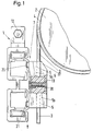
- Fig. 1 is a side view of a cable guide 1 for a hoist with both ends shown in a frame (not shown) rotatably mounted winch drum 2.
- the Winch drum 2 has two opposite rope grooves, not shown, each for one Rope 3 of a rope 4.
- the rope 4 or the rope strand 3 is at its beginning attached in the area of one end of the winch drum 2, runs from there through Rope grooves led to the winch drum 2 towards the center and leaves depending on Winding condition of the winch drum 2 at a point designated as the run-off point.
- the rope strand 3 then runs freely and is then guided by a rope guide channel 5 out, which is formed in a channel support 6 and part of a Guide element 7 is. After leaving the guide channel 5, the rope strand runs 3 towards a bottom block (not shown). The one emerging from the bottom block Rope will go back to the other end of the rope in reverse order Winch drum 2 out.
- the pair of guide elements 7 are over Coupling means (not shown) connected to one another in such a way that they only work together, however in the opposite direction on a rail 8 parallel to the axis of rotation of the Winch drum 2 are movable; the rail 8 is transverse to the axis of rotation of the Winch drum 2 around a parallel to the axis of rotation of the winch drum 2 Swivel axis 12 pivotally suspended on the winch.
- the pivot axis 12 is arranged in the region of the ends of the winch drum 2 on the frame; in these Areas of the unused part of the wound rope 4.
- Fig. 1 leaves the cross section of the cable guide channel 5 in a plane perpendicular to Recognize the axis of rotation of the winch drum 2; this has one at the top Input system section 5a for the cable 3 and an opposite one below Output system section 5b for the rope 3, which - as can be seen better in FIG. 2 - merge directly into one another.
- FIGS. 2 and 3 recognize that the rope 3 regardless of the direction of pull that is in all three Figures differs, in the input system section 5a on the right and in Output contact section 5b rests on the left side of the cable guide channel 5.
- the surface of the winch drum 2 facing Input system section 5a and the surface of the winch drum 2 facing away Output plant section 5b formed parallel to each other, i.
- the Cable guide channel 5 has its smallest cross-section in the middle area; to the The cross section increases continuously at the entrance and exit.
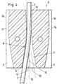
- 4 shows a cross section of the channel support 6 (corresponds to a plane parallel to the axis of rotation of the winch drum 2). 4 shows, the Rope guide channel 5 in a plane parallel to the axis of rotation of the winch drum 2 Input system section 5c and an opposite output system section 5d for the rope 3; here too in this cross-sectional plane it is ensured that the Rope 3 for different withdrawal angles of the rope 3 based on the Winding circumference of the winch drum 2 is guided tangentially.
- the Inlet section 5c and outlet section 5d go immediately continuously into each other.
- the guided rope strand is due to the Cross-sectional shape of the cable guide channel 5 in this plane on the left side of the Input system section 5c and on the left side of the Output plant section 5d, i. H. the cross-sectional shape of the cable guide channel in this plane ensures that the rope 3 is always on the same side (here the left Side).
- the cable strand 3 slides on the same continuous surface adjacent through the cable guide channel 5.
- the cross section of the cable guide channel 5 is the smallest Cross-sectional value in the middle area increases by a value that is less than is the cross section of the rope 3.
- the cross section of the Cable guide channel 5 symmetrical to the axis of symmetry 13, the Cross-sectional line 14 of the cable guide channel 5 towards the exit with an arc increasing bending radius R is formed.
- the guide elements 7 consist of channel supports 6, which consist of two pieces the same abutting support halves 6a, 6b are formed, in their respective half side cable guide channel 5 is formed on adjacent side surfaces 15, 16 is so that the rope 4 in the separating the support halves 6a, 6b Parting plane is guided almost bend-free.
- This dividing plane lies in the Swivel plane or at least parallel to this.
- they are each other adjacent side surfaces 15, 16 of the carrier halves 6a, 6b each opposite side surfaces 16, 17 with half a cable guide channel 5 Mistake.
- Fig. 5 shows that the channel support 6 is provided with an aligned groove 18 in the a connecting element 19 is inserted in a form-fitting manner and by means of screws 20 is firmly connected to the two support halves 6a, 6b.
- the Carrier halves 6a, 6b attached cam 21, which - as shown in Fig. 1 - in a complementary recess of the guide element 7 to produce a interlocking connection engages.
- the channel carrier expediently points 6 on the edge facing the winch drum 2, a bevel 22 (FIG. 1 to 3). When running against the rope 4, this runs essentially parallel to Tangential plane of the outer surface of the winch drum 2 in the contact point Bevel 22.
- the channel carrier 6 is made of a softer material than the rope 4.
- plastic especially polyamide, as well as relatively soft metals, especially aluminum, in Consideration.
Landscapes
- Engineering & Computer Science (AREA)
- Mechanical Engineering (AREA)
- Lift-Guide Devices, And Elevator Ropes And Cables (AREA)
- Conveying And Assembling Of Building Elements In Situ (AREA)
- Storage Of Web-Like Or Filamentary Materials (AREA)
Description
- Fig. 1
- eine teilgeschnittene Seitenansicht bei Abzug des Seils senkrecht nach unten,
- Fig. 2
- eine Seitenansicht der Seilführung gemäß Fig. 1 bei großem Abzugswinkel,
- Fig. 3
- die Seilführung gemäß Fig. 1 mit an der Windentrommel anliegender Abschrägung des Kanalträgers,
- Fig. 4
- einen Querschnitt des Kanalträgers und
- Fig. 5
- eine Vorderansicht des Kanalträgers.
- 1
- Seilführung
- 2
- Windentrommel
- 3
- Seilstrang
- 4
- Seil
- 5
- Seilführungskanal
- 5a
- Eingangsanlageabschnitt der ersten Ebene
- 5b
- Ausgangsanlageabschnitt der ersten Ebene
- 5c
- Eingangsanlageabschnitt der zweiten Ebene
- 5d
- Ausgangsanlageabschnitt der zweiten Ebene
- 6
- Kanalträger
- 6a,6b
- Kanalträgerhälfte
- 7
- Führungselement
- 8
- Schiene
- 12
- Schwenkachse
- 13
- Symmetrieachse
- 14
- Querschnittslinie
- 15,16
- Seitenfläche
- 17,17a
- Seitenfläche
- 18
- Nut
- 19
- Verbindungselement
- 20
- Schraube
- 21
- Nocken
- 22
- Abschrägung
- R
- Biegeradius
Claims (16)
- Seilführung (1) für ein Windwerk, insbesondere ein Hubwerk, mit einer gegenläufige Seilrillen aufweisenden und in einem Rahmen drehgelagerten Windentrommel (2), mit an zumindest einer Schiene (8) parallel zur Drehachse der Windentrommel verfahrbaren und zur Ausrichtung von zumindest einem Paar Seilstränge (3) in bezug auf die zugeordnete Seilrille vorgesehenen Führungsmitteln (7), die über Kopplungsmittel gegenläufig miteinander verbunden und von den aufwickelbaren oder abwickelbaren Seilsträngen antreibbar sind und Führungselemente (7) aufweisen, wobei die Schiene (8) quer zur Drehachse der Windentrommel um eine parallel zur Drehachse der Windentrommel verlaufende Schwenkachse verschwenkbar am Windwerk angeordnet ist,
dadurch gekennzeichnet, daß die Führungselemente ( 7 ) jeweils einen in einem Kanalträger ( 6 ) ausgebildeten Seilführungskanal ( 5 ) umfassen, der in einer ersten Ebene senkrecht zur Drehachse der Windentrommel ( 2 ) einen Eingangsanlageabschnitt ( 5a ) für ein Seil ( 4 ) und einen gegenüberliegenden Ausgangsanlageabschnitt ( 5b ) für das Seil ( 4 ) und der in einer zweiten Ebene parallel zur Drehachse der Windentrommel ( 2 ) einen Eingangsanlageabschnitt ( 5c ) für das Seil ( 4 ) und einen gegenüberliegenden Ausgangsanlageabschnitt ( 5d ) für das Seil ( 4 ) aufweist, und daß der Seilführungskanal ( 5 ) im mittleren Bereich seinen kleinsten Querschnitt hat, der zum Eingang und Ausgang hin wieder zunimmt. - Seilführung nach Anspruch 1,
dadurch gekennzeichnet, daß der Eingangsanlageabschnitt ( 5a, 5c ) und der Ausgangsanlageabschnitt ( 5b, 5d ) der korrespondierenden Ebene unmittelbar aufeinanderfolgend angeordnet sind. - Seilführung nach Anspruch 1 oder 2,
dadurch gekennzeichnet, daß der Seilführungskanal ( 5 ) derart ausgebildet ist, daß der geführte Seilstrang ( 3 ) auf einer Seite der jeweiligen Eingangsanlageabschnitte (5a, 5c) und auf einer Seite der jeweiligen Ausgangsanlageabschnitte (5b, 5d) anliegt. - Seilführung nach einem der Ansprüche 1 bis 3,
dadurch gekennzeichnet, daß der Seilführungskanal ( 5 ) derart ausgebildet ist, daß der geführte Seilstrang ( 3 ) in der ersten Ebene senkrecht zur Drehachse der Windentrommel ( 2 ) im Eingangsanlageabschnitt (5a) auf der einen Seite und im Ausgangsanlageabschnitt (5b) auf der anderen Seite anliegt. - Seilführung nach einem der Ansprüche 1 bis 4,
dadurch gekennzeichnet, daß die der Windentrommel ( 2 ) zugewandte Fläche des Eingangsanlageabschnitts (5a) und die der Windentrommel ( 2 ) abgewandte Fläche des Ausgangsanlageabschnitts (5b) im wesentlichen parallel zueinander ausgebildet sind. - Seilführung nach einem der Ansprüche 1 bis 5,
dadurch gekennzeichnet, daß die der Windentrommel ( 2 ) abgewandte Fläche des Eingangsanlageabschnitts (5a) und die der Windentrommel ( 2 ) zugewandte Fläche des Ausgangsanlageabschnitt (5b) im wesentlichen parallel zueinander ausgebildet sind. - Seilführung nach einem der Ansprüche 1 bis 6,
dadurch gekennzeichnet, daß der Seilführungskanal ( 5 ) derart ausgebildet ist, daß der geführte Seilstrang ( 3 ) in der zweiten Ebene parallel zur Drehachse der Windentrommel ( 2 ) im Eingangsanlageabschnitt (5c) und im Ausgangsanlageabschnitt (5d) auf derselben Fläche anliegt. - Seilführung nach einem der Ansprüche 1 bis 7,
dadurch gekennzeichnet, daß der Querschnitt des Seilführungskanals ( 5 ) in der zweiten Ebene parallel zur Drehachse der Windentrommel ( 2 ) zum Eingang hin um einen Wert zunimmt, der kleiner als der Querschnitt des Seils ( 4 ) ist. - Seilführung nach einem der Ansprüche 1 bis 8,
dadurch gekennzeichnet, daß der Querschnitt des Seilführungskanals ( 5 ) in der zweiten Ebene parallel zur Drehachse der Windentrommel ( 2 ) zum Ausgang hin symmetrisch zur Symmetrieachse ( 13 ) des Seilführungskanals ( 5 ) zunimmt. - Seilführung nach einem der Ansprüche 1 bis 9,
dadurch gekennzeichnet, daß die Querschnittslinie ( 14 ) des Seilführungskanals ( 5 ) in der zweiten Ebene parallel zur Drehachse der Windentrommel ( 2 ) im Ausgangsanlageabschnitt ( 5d ) zum Ausgang hin bogenförmig mit zunehmendem Biegeradius (R) ausgebildet ist. - Seilführung für ein Windwerk, insbesondere ein Hubwerk, mit einer gegenläufige Seilrillen aufweisenden und in einem Rahmen drehgelagerten Windentrommel (2), mit an zumindest einer Schiene (8) parallel zur Drehachse der Windentrommel verfahrbaren und zur Ausrichtung von zumindest einem Paar Seilstränge in bezug auf die zugeordnete Seilrille vorgesehenen Führungsmitteln, die über Kopplungsmittel gegenläufig miteinander verbunden und von den aufwickelbaren oder abwickelbaren Seilsträngen antreibbar sind und Führungselemente aufweisen, wobei die Schiene (8) quer zur Drehachse der Windentrommel um eine parallel zur Drehachse der Windentrommel verlaufende Schwenkachse verschwenkbar am Windwerk angeordnet ist,
dadurch gekennzeichnet, daß die Führungselemente jeweils einen in einem Kanalträger ( 6 ) ausgebildeten Seilführungskanal ( 5 ) umfassen, daß der Kanalträger ( 6 ) aus zwei gleichen aneinanderliegenden Trägerhälften ( 6a, 6b ) besteht und daß die aneinanderliegenden Seitenflächen ( 15, 16 ) der Trägerhälften ( 6a, 6b ) jeweils einen halben Seilführungskanal ( 5 ) bilden und daß die senkrechte Projektion des Seiles auf die Trennebene, die jeweils in der Schwenkebene oder parallel zu dieser liegt, im wesentlichen biegungsfrei ist. - Seilführung nach Anspruch 11,
dadurch gekennzeichnet, daß die Seitenflächen ( 17, 17a ), die den aneinanderliegenden Seitenflächen (15, 16) der Trägerhälften ( 6a, 6b ) jeweils gegenüberliegen, parallel zueinander ausgebildet und zusätzlich mit einem halben Seilführungskanal ( 5 ) versehen sind. - Seilführung nach einem der Ansprüche 11 oder 12,
dadurch gekennzeichnet, daß der aus zwei Trägerhälften ( 6a, 6b ) bestehende Kanalträger ( 6 ) quer zur Kanallängsachse mit einer fluchtenden Nut ( 18 ) versehen ist, in die ein Verbindungselement ( 19 ) formschlüssig eingesetzt ist und daß das Verbindungselement ( 19 ) mit den beiden Trägerhälften ( 6a, 6b ) verbunden ist. - Seilführung nach einem der Ansprüche 11 bis 13,
dadurch gekennzeichnet, daß die Trägerhätften ( 6a, 6b ) jeweils mit einem Nocken versehen sind, der formschlüssig in eine komplementäre Vertiefung des Führungselements ( 7 ) zur Erzeugung einer verdrehgesicherten Verbindung eingreift. - Seilführung nach einem der Ansprüche 1 bis 10,
dadurch gekennzeichnet, daß der Kanalträger ( 6 ) aus einem weicheren Material als das Seil ( 4 ) ausgeführt ist. - Seilführung nach einem der Ansprüche 1 bis 11,
dadurch gekennzeichnet, daß die der Windentrommel ( 2 ) zugewandte Kante des Kanalträgers ( 6 ) mit einer Abschrägung (22) versehen ist.
Applications Claiming Priority (2)
| Application Number | Priority Date | Filing Date | Title |
|---|---|---|---|
| DE19613712 | 1996-03-29 | ||
| DE19613712A DE19613712C2 (de) | 1996-03-29 | 1996-03-29 | Seilführung für ein Windwerk |
Publications (3)
| Publication Number | Publication Date |
|---|---|
| EP0798258A2 EP0798258A2 (de) | 1997-10-01 |
| EP0798258A3 EP0798258A3 (de) | 1998-12-09 |
| EP0798258B1 true EP0798258B1 (de) | 2003-05-07 |
Family
ID=7790594
Family Applications (1)
| Application Number | Title | Priority Date | Filing Date |
|---|---|---|---|
| EP97250101A Expired - Lifetime EP0798258B1 (de) | 1996-03-29 | 1997-03-26 | Seilführung für ein Windwerk |
Country Status (5)
| Country | Link |
|---|---|
| US (1) | US5863029A (de) |
| EP (1) | EP0798258B1 (de) |
| JP (1) | JPH1029792A (de) |
| KR (1) | KR100441909B1 (de) |
| DE (2) | DE19613712C2 (de) |
Families Citing this family (9)
| Publication number | Priority date | Publication date | Assignee | Title |
|---|---|---|---|---|
| CA2227801A1 (en) * | 1997-03-15 | 1998-09-15 | Theodor Kromer Gmbh Unternehmensgruppe Unican | Device for equalizing weight of a hanging load |
| DE19911073C2 (de) * | 1999-03-12 | 2003-04-30 | Rotzler Gmbh Co | Seilfenster für Seilwinden |
| JP2002362881A (ja) * | 2001-06-07 | 2002-12-18 | Kurihara Kogyo Co Ltd | ワイヤロープテンショナ |
| EP1528032A4 (de) * | 2002-04-23 | 2010-03-31 | Panasonic Elec Works Co Ltd | Aufzug |
| DE10349235A1 (de) * | 2003-10-20 | 2005-05-19 | Rotzler Gmbh & Co. Kg | Seilführung für das Zugseil an einer Winde an einem Kraftfahrzeug oder dgl. |
| FR2900141B3 (fr) | 2006-04-21 | 2008-07-11 | Paillardet S A Sa | Treuil de levage |
| MX2010002112A (es) * | 2007-08-24 | 2010-03-26 | Heerema Marine Contractors Nl | Dispositivo de desplazamiento axial, sistema de distribucion de linea, y un metodo para distribuir una linea. |
| FI128653B (fi) * | 2019-03-29 | 2020-09-30 | Konecranes Global Oy | Köysinostimen köydenohjauslaite |
| US12434950B2 (en) * | 2023-03-14 | 2025-10-07 | Rexon Industrial Corp., Ltd. | Cable guiding assembly |
Family Cites Families (16)
| Publication number | Priority date | Publication date | Assignee | Title |
|---|---|---|---|---|
| DE41908C (de) * | DEUTSCHE BLECHBEARBEITUNGSMASCHINENFABRIK, ERNST LINDEMANN & Co. in Chemnitz i. S | Abkantemaschine | ||
| DD41908A (de) * | ||||
| US1524198A (en) * | 1924-01-17 | 1925-01-27 | Morgan Engineering Co | Safety device for traveling cranes and the like |
| US2238398A (en) * | 1937-05-22 | 1941-04-15 | John E Reed | Line spooler |
| GB543323A (en) * | 1940-10-21 | 1942-02-19 | Leith Cardle And Company Ltd | Improvements relating to hoist blocks, cranes, winches and the like |
| US2347885A (en) * | 1941-11-14 | 1944-05-02 | Charles S Crickmer | Wire line guide |
| US2738143A (en) * | 1955-04-07 | 1956-03-13 | Clifford B Hannay & Son Inc | Hose reel |
| US2984455A (en) * | 1957-08-06 | 1961-05-16 | California Research Corp | Multiple-cable tensioning device |
| US3215405A (en) * | 1962-11-06 | 1965-11-02 | Breeze Corp | Fleet angle control device |
| US3226090A (en) * | 1963-06-18 | 1965-12-28 | Aircraft Armaments Inc | Materials handling arrangement |
| CH579194A5 (de) * | 1971-06-14 | 1976-08-31 | Mannesmann Leichtbau Gmbh | |
| FR2190641B1 (de) * | 1972-06-26 | 1976-01-16 | Aerazur Constr Aeronaut | |
| US4083510A (en) * | 1976-06-14 | 1978-04-11 | Mccaffrey-Ruddock Tagline Corporation | Self-adjusting fairlead for spring rewound tagline device |
| GB2061861B (en) * | 1979-10-25 | 1983-05-05 | Aabacas Eng Co Ltd | Rope guides for hoists |
| DE4241655C1 (de) * | 1992-12-04 | 1994-04-21 | Mannesmann Ag | Seilführung für ein Windwerk, insbesondere ein Hubwerk |
| FR2711632B1 (fr) * | 1993-10-28 | 1996-02-23 | Jacky Perrin | Dispositif permettant l'enroulement à spires jointives d'un câble sur un tambour. |
-
1996
- 1996-03-29 DE DE19613712A patent/DE19613712C2/de not_active Expired - Fee Related
-
1997
- 1997-03-21 KR KR1019970009844A patent/KR100441909B1/ko not_active Expired - Fee Related
- 1997-03-21 US US08/823,315 patent/US5863029A/en not_active Expired - Lifetime
- 1997-03-26 EP EP97250101A patent/EP0798258B1/de not_active Expired - Lifetime
- 1997-03-26 DE DE59710007T patent/DE59710007D1/de not_active Expired - Lifetime
- 1997-03-28 JP JP9094592A patent/JPH1029792A/ja active Pending
Also Published As
| Publication number | Publication date |
|---|---|
| DE19613712C2 (de) | 1998-09-10 |
| KR100441909B1 (ko) | 2004-10-08 |
| DE59710007D1 (de) | 2003-06-12 |
| EP0798258A3 (de) | 1998-12-09 |
| EP0798258A2 (de) | 1997-10-01 |
| KR970065400A (ko) | 1997-10-13 |
| DE19613712A1 (de) | 1997-10-02 |
| JPH1029792A (ja) | 1998-02-03 |
| US5863029A (en) | 1999-01-26 |
Similar Documents
| Publication | Publication Date | Title |
|---|---|---|
| DE19613712C2 (de) | Seilführung für ein Windwerk | |
| DE69508847T2 (de) | Doppeltwirkende Klemme zum Ankuppeln eines Fahrzeuges an das Zugkabel | |
| EP1035068A2 (de) | Seilfenster für Seilwinden | |
| EP0281205B1 (de) | Umlaufseilbahnanlage mit Ablenkung des Zug-Tragseilverlaufes | |
| DE19732451C2 (de) | Seilanordnung zur Aufhängung eines Anschlagmittels an einem Hubwerk, insbesondere für Laufkrane oder Laufkatzen | |
| DE102008034360C5 (de) | Aus einem D-Profilstahlabschnitt hergestelltes Kettenglied, insbesondere für eine Hebezeugkette | |
| DE3421843C2 (de) | ||
| AT407379B (de) | Seilführung für ein windwerk, insbesondere ein hubwerk | |
| DE60308152T2 (de) | Kran | |
| DE29623018U1 (de) | Seilführung | |
| DE1202089B (de) | Vorrichtung zur Fuehrung und Lagerung von biegsamen Leitungen od. dgl. | |
| DE69514161T2 (de) | Auf flachen biegsamen Gurten wirkende Zug- oder Hebevorrichtung mit Backen | |
| DE2332888A1 (de) | Stranggiessanlage | |
| DE3331872A1 (de) | Hubvorrichtung | |
| DE2248386A1 (de) | Greifer | |
| DE3937080C2 (de) | Hubseil-Stützvorrichtung für einen Auslegerkran | |
| DE3011348C2 (de) | ||
| DE19916791A1 (de) | Energieführungskette | |
| DE2733803C3 (de) | Rollenfenster zur Seilführung bei Seilbahnen des Untertagebetriebes | |
| DE19902891C2 (de) | Einrichtung mit einer Seilanordnung | |
| AT234932B (de) | Stützwalzengerüst zur Führung eines gebogenen Gießstranges in einer Stahl- oder Metallstranggießanlage | |
| DE69501576T2 (de) | Schwenkvorrichtung | |
| DE102008059074B3 (de) | Seilflasche | |
| DE10135034C1 (de) | Hubwerk mit einer Seilanordnung | |
| AT316038B (de) | Vorrichtung zur Führung einer oszillierend bewegten Stranggießkokille bei einer Stranggießanlage mit gebogener Strangbahnachse |
Legal Events
| Date | Code | Title | Description |
|---|---|---|---|
| PUAI | Public reference made under article 153(3) epc to a published international application that has entered the european phase |
Free format text: ORIGINAL CODE: 0009012 |
|
| AK | Designated contracting states |
Kind code of ref document: A2 Designated state(s): DE FR GB IT |
|
| PUAL | Search report despatched |
Free format text: ORIGINAL CODE: 0009013 |
|
| AK | Designated contracting states |
Kind code of ref document: A3 Designated state(s): DE FR GB IT |
|
| 17P | Request for examination filed |
Effective date: 19990527 |
|
| 17Q | First examination report despatched |
Effective date: 20011102 |
|
| GRAH | Despatch of communication of intention to grant a patent |
Free format text: ORIGINAL CODE: EPIDOS IGRA |
|
| RAP1 | Party data changed (applicant data changed or rights of an application transferred) |
Owner name: DEMAG CRANES & COMPONENTS GMBH |
|
| GRAH | Despatch of communication of intention to grant a patent |
Free format text: ORIGINAL CODE: EPIDOS IGRA |
|
| GRAA | (expected) grant |
Free format text: ORIGINAL CODE: 0009210 |
|
| AK | Designated contracting states |
Designated state(s): DE FR GB IT |
|
| REG | Reference to a national code |
Ref country code: GB Ref legal event code: FG4D Free format text: NOT ENGLISH |
|
| GBT | Gb: translation of ep patent filed (gb section 77(6)(a)/1977) |
Effective date: 20030507 |
|
| REF | Corresponds to: |
Ref document number: 59710007 Country of ref document: DE Date of ref document: 20030612 Kind code of ref document: P |
|
| ET | Fr: translation filed | ||
| PLBE | No opposition filed within time limit |
Free format text: ORIGINAL CODE: 0009261 |
|
| STAA | Information on the status of an ep patent application or granted ep patent |
Free format text: STATUS: NO OPPOSITION FILED WITHIN TIME LIMIT |
|
| 26N | No opposition filed |
Effective date: 20040210 |
|
| REG | Reference to a national code |
Ref country code: FR Ref legal event code: PLFP Year of fee payment: 19 |
|
| PGFP | Annual fee paid to national office [announced via postgrant information from national office to epo] |
Ref country code: DE Payment date: 20150320 Year of fee payment: 19 Ref country code: IT Payment date: 20150326 Year of fee payment: 19 |
|
| PGFP | Annual fee paid to national office [announced via postgrant information from national office to epo] |
Ref country code: FR Payment date: 20150319 Year of fee payment: 19 Ref country code: GB Payment date: 20150319 Year of fee payment: 19 |
|
| REG | Reference to a national code |
Ref country code: DE Ref legal event code: R119 Ref document number: 59710007 Country of ref document: DE |
|
| GBPC | Gb: european patent ceased through non-payment of renewal fee |
Effective date: 20160326 |
|
| REG | Reference to a national code |
Ref country code: FR Ref legal event code: ST Effective date: 20161130 |
|
| PG25 | Lapsed in a contracting state [announced via postgrant information from national office to epo] |
Ref country code: GB Free format text: LAPSE BECAUSE OF NON-PAYMENT OF DUE FEES Effective date: 20160326 Ref country code: DE Free format text: LAPSE BECAUSE OF NON-PAYMENT OF DUE FEES Effective date: 20161001 Ref country code: FR Free format text: LAPSE BECAUSE OF NON-PAYMENT OF DUE FEES Effective date: 20160331 |
|
| PG25 | Lapsed in a contracting state [announced via postgrant information from national office to epo] |
Ref country code: IT Free format text: LAPSE BECAUSE OF NON-PAYMENT OF DUE FEES Effective date: 20160326 |