EP0794312B1 - Stahlmöbeltür und Eckverbindung - Google Patents
Stahlmöbeltür und Eckverbindung Download PDFInfo
- Publication number
- EP0794312B1 EP0794312B1 EP97102190A EP97102190A EP0794312B1 EP 0794312 B1 EP0794312 B1 EP 0794312B1 EP 97102190 A EP97102190 A EP 97102190A EP 97102190 A EP97102190 A EP 97102190A EP 0794312 B1 EP0794312 B1 EP 0794312B1
- Authority
- EP
- European Patent Office
- Prior art keywords
- door
- corner
- sheet metal
- tray
- termination
- Prior art date
- Legal status (The legal status is an assumption and is not a legal conclusion. Google has not performed a legal analysis and makes no representation as to the accuracy of the status listed.)
- Expired - Lifetime
Links
- 229910000831 Steel Inorganic materials 0.000 title claims description 25
- 239000010959 steel Substances 0.000 title claims description 25
- 229910052751 metal Inorganic materials 0.000 claims abstract description 53
- 239000002184 metal Substances 0.000 claims abstract description 53
- 239000011888 foil Substances 0.000 claims description 9
- 239000000853 adhesive Substances 0.000 claims description 4
- 230000001154 acute effect Effects 0.000 claims description 2
- 238000002788 crimping Methods 0.000 claims 4
- 239000005030 aluminium foil Substances 0.000 claims 1
- 239000011087 paperboard Substances 0.000 claims 1
- 238000009413 insulation Methods 0.000 abstract description 33
- 229910052782 aluminium Inorganic materials 0.000 abstract description 9
- XAGFODPZIPBFFR-UHFFFAOYSA-N aluminium Chemical compound [Al] XAGFODPZIPBFFR-UHFFFAOYSA-N 0.000 abstract description 9
- 238000003780 insertion Methods 0.000 abstract description 5
- 230000037431 insertion Effects 0.000 abstract description 5
- 238000007789 sealing Methods 0.000 abstract description 5
- 239000004411 aluminium Substances 0.000 abstract 1
- 238000004519 manufacturing process Methods 0.000 description 12
- 238000013461 design Methods 0.000 description 10
- 238000000034 method Methods 0.000 description 5
- 238000000576 coating method Methods 0.000 description 4
- 238000005516 engineering process Methods 0.000 description 4
- 238000005304 joining Methods 0.000 description 4
- 230000008569 process Effects 0.000 description 4
- 239000002699 waste material Substances 0.000 description 4
- 230000015572 biosynthetic process Effects 0.000 description 3
- 239000011248 coating agent Substances 0.000 description 3
- 238000007688 edging Methods 0.000 description 3
- 239000003292 glue Substances 0.000 description 3
- 231100000331 toxic Toxicity 0.000 description 3
- 230000002588 toxic effect Effects 0.000 description 3
- 229910000851 Alloy steel Inorganic materials 0.000 description 2
- 230000008901 benefit Effects 0.000 description 2
- 239000003795 chemical substances by application Substances 0.000 description 2
- 239000002131 composite material Substances 0.000 description 2
- 238000010276 construction Methods 0.000 description 2
- 230000009189 diving Effects 0.000 description 2
- 239000006260 foam Substances 0.000 description 2
- 238000005470 impregnation Methods 0.000 description 2
- 150000004767 nitrides Chemical class 0.000 description 2
- 230000006911 nucleation Effects 0.000 description 2
- 238000010899 nucleation Methods 0.000 description 2
- 230000035515 penetration Effects 0.000 description 2
- 125000006850 spacer group Chemical group 0.000 description 2
- KXGFMDJXCMQABM-UHFFFAOYSA-N 2-methoxy-6-methylphenol Chemical compound [CH]OC1=CC=CC([CH])=C1O KXGFMDJXCMQABM-UHFFFAOYSA-N 0.000 description 1
- ATJFFYVFTNAWJD-UHFFFAOYSA-N Tin Chemical compound [Sn] ATJFFYVFTNAWJD-UHFFFAOYSA-N 0.000 description 1
- 230000001070 adhesive effect Effects 0.000 description 1
- 239000012790 adhesive layer Substances 0.000 description 1
- 238000004873 anchoring Methods 0.000 description 1
- 239000011324 bead Substances 0.000 description 1
- 238000005452 bending Methods 0.000 description 1
- 238000004140 cleaning Methods 0.000 description 1
- 238000004040 coloring Methods 0.000 description 1
- 238000012937 correction Methods 0.000 description 1
- 238000013016 damping Methods 0.000 description 1
- 230000001934 delay Effects 0.000 description 1
- 238000011161 development Methods 0.000 description 1
- 230000000694 effects Effects 0.000 description 1
- 230000002349 favourable effect Effects 0.000 description 1
- 238000005187 foaming Methods 0.000 description 1
- 230000006872 improvement Effects 0.000 description 1
- 238000010422 painting Methods 0.000 description 1
- 239000005011 phenolic resin Substances 0.000 description 1
- 229920001568 phenolic resin Polymers 0.000 description 1
- 239000000843 powder Substances 0.000 description 1
- 238000003825 pressing Methods 0.000 description 1
- 238000012545 processing Methods 0.000 description 1
- 238000004080 punching Methods 0.000 description 1
- 238000004064 recycling Methods 0.000 description 1
- 230000000284 resting effect Effects 0.000 description 1
- 238000005096 rolling process Methods 0.000 description 1
- 238000007788 roughening Methods 0.000 description 1
- 238000003892 spreading Methods 0.000 description 1
- 230000007480 spreading Effects 0.000 description 1
- 230000007704 transition Effects 0.000 description 1
- XLYOFNOQVPJJNP-UHFFFAOYSA-N water Substances O XLYOFNOQVPJJNP-UHFFFAOYSA-N 0.000 description 1
- 238000003466 welding Methods 0.000 description 1
Images



Classifications
-
- F—MECHANICAL ENGINEERING; LIGHTING; HEATING; WEAPONS; BLASTING
- F16—ENGINEERING ELEMENTS AND UNITS; GENERAL MEASURES FOR PRODUCING AND MAINTAINING EFFECTIVE FUNCTIONING OF MACHINES OR INSTALLATIONS; THERMAL INSULATION IN GENERAL
- F16B—DEVICES FOR FASTENING OR SECURING CONSTRUCTIONAL ELEMENTS OR MACHINE PARTS TOGETHER, e.g. NAILS, BOLTS, CIRCLIPS, CLAMPS, CLIPS OR WEDGES; JOINTS OR JOINTING
- F16B12/00—Jointing of furniture or the like, e.g. hidden from exterior
- F16B12/44—Leg joints; Corner joints
- F16B12/46—Non-metal corner connections
-
- E—FIXED CONSTRUCTIONS
- E06—DOORS, WINDOWS, SHUTTERS, OR ROLLER BLINDS IN GENERAL; LADDERS
- E06B—FIXED OR MOVABLE CLOSURES FOR OPENINGS IN BUILDINGS, VEHICLES, FENCES OR LIKE ENCLOSURES IN GENERAL, e.g. DOORS, WINDOWS, BLINDS, GATES
- E06B3/00—Window sashes, door leaves, or like elements for closing wall or like openings; Layout of fixed or moving closures, e.g. windows in wall or like openings; Features of rigidly-mounted outer frames relating to the mounting of wing frames
- E06B3/70—Door leaves
- E06B3/82—Flush doors, i.e. with completely flat surface
- E06B3/827—Flush doors, i.e. with completely flat surface of metal without an internal frame, e.g. with exterior panels substantially of metal
-
- E—FIXED CONSTRUCTIONS
- E06—DOORS, WINDOWS, SHUTTERS, OR ROLLER BLINDS IN GENERAL; LADDERS
- E06B—FIXED OR MOVABLE CLOSURES FOR OPENINGS IN BUILDINGS, VEHICLES, FENCES OR LIKE ENCLOSURES IN GENERAL, e.g. DOORS, WINDOWS, BLINDS, GATES
- E06B3/00—Window sashes, door leaves, or like elements for closing wall or like openings; Layout of fixed or moving closures, e.g. windows in wall or like openings; Features of rigidly-mounted outer frames relating to the mounting of wing frames
- E06B3/70—Door leaves
- E06B3/7015—Door leaves characterised by the filling between two external panels
- E06B2003/703—Door leaves characterised by the filling between two external panels containing a metallic layer
-
- E—FIXED CONSTRUCTIONS
- E06—DOORS, WINDOWS, SHUTTERS, OR ROLLER BLINDS IN GENERAL; LADDERS
- E06B—FIXED OR MOVABLE CLOSURES FOR OPENINGS IN BUILDINGS, VEHICLES, FENCES OR LIKE ENCLOSURES IN GENERAL, e.g. DOORS, WINDOWS, BLINDS, GATES
- E06B3/00—Window sashes, door leaves, or like elements for closing wall or like openings; Layout of fixed or moving closures, e.g. windows in wall or like openings; Features of rigidly-mounted outer frames relating to the mounting of wing frames
- E06B3/70—Door leaves
- E06B2003/7048—Door leaves with arcuate periphery; with openings having an arcuate periphery
-
- E—FIXED CONSTRUCTIONS
- E06—DOORS, WINDOWS, SHUTTERS, OR ROLLER BLINDS IN GENERAL; LADDERS
- E06B—FIXED OR MOVABLE CLOSURES FOR OPENINGS IN BUILDINGS, VEHICLES, FENCES OR LIKE ENCLOSURES IN GENERAL, e.g. DOORS, WINDOWS, BLINDS, GATES
- E06B3/00—Window sashes, door leaves, or like elements for closing wall or like openings; Layout of fixed or moving closures, e.g. windows in wall or like openings; Features of rigidly-mounted outer frames relating to the mounting of wing frames
- E06B3/70—Door leaves
- E06B3/7015—Door leaves characterised by the filling between two external panels
- E06B3/7017—Door leaves characterised by the filling between two external panels of grating type
Definitions
- the invention relates to a steel furniture door and a corner connection according to the preambles of claim 1 and claim 11.
- Sheet steel constructions have become common for many uses because they relatively easy to manufacture; to be transported and set up. In the office- and workshop facilities have such furniture designs thanks to their Proven robustness and practicality.
- Honeycomb cardboard is usually used for structure-borne sound insulation in steel furniture doors two door shells glued. Because cardboard due to its hygroscopic properties becomes slightly damp, it can lead to the formation of germ spots. It is known the honeycomb cardboard with phenolic resin or with an anti-mold impregnation coat. However, this is very complex and does not lead to a complete correction of the problem. Another disadvantage is that the coated cardboard as a composite material can only be disposed of as special waste.
- a door leaf disclosed in AT-B-380 921 This consists of two sheet metal shells with a flat insulation insert glued in between, the two door shells with locking means for releasable attachment to each other are provided in such a way that a first door shell is fixed in the correct position Insulation insert can be snapped into the second door shell.
- the insulation insert does exist not made of corrugated cardboard, which affects the recyclability. It is also not protected against the ingress of moisture, so that mold and Nucleation can occur.
- EP-A1-0 081 249 describes a box-shaped furniture element, in particular a Door leaf, a table top or the like, with a base plate made of relatively thin sheet metal as well molded side faces. The latter are on their mutually facing end edges shortened so that recesses in the corner areas of the element arise in which a corner part can be inserted form-fitting from the inside.
- the corner part lies with two longitudinally formed wing attachments and with the ends provided wall parts flat on the side surfaces or the base plate on and is glued to it, which delays the further assembly of the door. Only by foaming of the box-shaped element with an insulating foam Corner element fully anchored in position. However, this is not only complex and expensive to manufacture. The foam also makes it difficult to recycle Door that has to be disposed of as a complex component.
- An important goal of the invention is to create a fully recyclable steel furniture door to develop with an insulation insert that can not absorb any moisture, whereby the manufacturing effort compared to conventional technology can be reduced should.
- the door should be reworkable together with the insulation insert be without producing toxic or environmentally harmful waste products.
- Another object of the invention is to use the most economical means possible low investment a new connection of door sheet metal parts without large Manufacture investment costs that fit comfortably, reliably and quickly leaves. Furthermore, a new type of corner connection is to be created that is effortless and can be assembled precisely without restricting the recyclability of the entire door. The possibilities of different design make it easy to adapt various purposes and spatial conditions sought.
- the two door shells with locking means for detachable Attachment to each other are provided such that a first door shell under the correct position
- the invention provides for fixing the insulation insert into the second door shell according to claim 1, that the insulating insert has a cardboard honeycomb structure and all around with a waterproof, self-adhesive coating on one or both sides Foil made of aluminum, which is full on both main surfaces of the insulation insert is present.
- the finished steel furniture door is ecologically harmless and complete recyclable. It can be melted down together with the insulation insert, whereby the Honeycomb cardboard burns and the aluminum of the foil is alloyed with the steel sheet.
- the Aluminum supports fine grain formation as a strong deoxidizing and denitrifying agent and increases the scaling resistance of the steel alloy that is formed characterized by high hardness nitrides. Toxic or environmentally harmful waste products do not arise.
- the insulation insert is enveloped by the film overlapping the entire surface, which on opposite sides, especially on the narrow sides the insulation insert, each has a sealing rebate. This takes care of you tight seal of the film and can be manufactured inexpensively. The fully assembled The door and the cardboard can therefore be completely picked up in a diving system and then painted without damaging the insert. Elaborate Coating and impregnation processes are not necessary; the handling in production is considerably simplified.
- At least one sealing rebate according to claim 3 is expedient on or in a door shell can be anchored, especially on pre-embossed or punched sheet metal projections, tabs o. The like. So that the insulation insert is held exactly inside the door.
- the insulating insert before locking the door shells is glued snugly against the inside surface of a door shell. This is how you achieve a significant improvement in the structure-borne noise insulation value. Thanks sufficient The strength of the encapsulated insulation insert is no longer necessary for the connection Fasteners needed; the manufacturing effort is correspondingly low. It results there is a stable connection between the sheet metal parts, which is therefore relatively large loads can record.
- This shape can be manufacturing technology in a simple and economical way.
- the fast assembly is still supported if the envelope according to claim 6 one for Has inner surface of a door shell directed stop, for example a free outlet edge, a roll or flare fold u. the like
- the bends of the other door shell can be according to claim 7 at one edge Step and be formed on the opposite edge as a detent spring, the Step along one inner shell edge essentially over its entire length Length runs and at the stop, under it, at least non-positively is definable. So you not only have a selective attachment, but one with relatively large areas of effective locking of the two door shells which can be easily separated from each other if necessary.
- stage according to claim 8 is three-legged and one of the Surface of the inner shell, projecting legs projecting essentially at right angles, one of these outward-facing under hook legs and one of the latter has end legs bent backwards, preferably at right angles or acute angles, an optimal support is achieved on the assigned edge envelope Outer shell.
- the system leg and the detent spring Inner shell to the depth and shape of the assigned outer shell stop are adapted, the end leg of the step acting as a spacer can.
- the outer surface of the locked inner shell is then aligned with a cover surface of the outer shell envelope.
- the sheet metal parts can be made according to the desired Design with different or similar surface design, e.g. B. coloring be added.
- the detent spring can be an insertion slope or curvature and / or a curvature, rib, clip edge or the like which can be positively fixed to the stop. exhibit.
- a corner connection with flat sheet metal parts and with one on free sheet metal part edges form-lockable corner finish, which in a shape and dimensions the sheet metal parts to be connected is adapted body, in particular for a steel furniture door according to one of claims 1 to 10, is characterized according to the independent Claim 11 characterized by the corner finish on at least one of the to be connected Sheet metal parts can be locked by simply pressing them in by hand, the corner finish has at least two spring catches arranged near its outer regions, which when clipping the free edges of at least one sheet metal part in the Reach under or behind the locking position and on the clipped corner finish from the outside are not recognizable.
- each spring catch has a sliding surface, that when clipping in the corner finish with little friction on a free sheet metal edge passes, and has a holding surface, which in the locking position on this Sheet metal part edge engages non-positively, in particular frictionally.
- the component is used for guidance when clipping and for locking in the End position, which can be provided according to claim 15 that the sliding surface with the Holding surface includes an angle, namely a right or obtuse angle, so that directly at the transition between the two surfaces Rest process begins. It is facilitated by the sliding surface with respect to the direction of movement the spring catch runs obliquely or arched, making an insertion aid given is.
- the locking according to claim 16 is supported in that the holding surface Has friction and / or positive locking means for the free sheet metal part edge, -z.
- the sliding surfaces of two spring catches can be particularly advantageous are at an angle to each other, especially at right angles, so that transverse locking forces - preferably directed apart, therefore spreading - act.
- corner finish a hollow body with flat recesses to accommodate flush fit Ends of the sheet metal parts.
- the invention provides for a corner connection for a steel furniture door of the aforementioned type according to claim 19 further that a folding frame and one with longitudinal bends provided sheet metal shell together form a door leaf, a panel or the like. That the folding frame has corner notches, into each of which a corner end can be clipped, and that in turn at least one of the sheet metal shell essentially vertically protruding tab can be inserted, in or at the rest position a spring catch of the corner end comes to rest, which makes one extremely achieved simple possibility of sheet metal part definition.
- the corner is in a direction transverse to the main expansion surface at least one sheet metal part can be clipped in, so that does not only bring about an advantageous quick assembly method, but also a high one in this transverse direction Dimensional stability of the composite body.
- the steel furniture door shown in FIG. 1, generally designated 10, has one Outer shell 12, a damping insert 14 and an inner shell 16.
- the latter has receptacles 22, 24 for hinges (not shown) or Locking devices on.
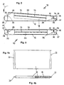
- Between the two door shells 12, 16 is one Insulating insert 14 arranged, which - as shown on a broken Corner can be seen - has a honeycomb structure W and is enclosed by a film 18 is. This has protruding edges on the narrow sides that form tight folds 20 are closed overlapping.
- the outer shell 12 has an envelope 30 that is folded toward the inside provided which has a stop 32 and a top surface 34. He participates Components of the inner shell 16 together, one along a long side Step 26 and along the opposite long side has a detent spring 28.
- Fig. 1 These folded sheet metal parts are shown schematically in Fig. 1 by the circles marked areas shown in enlarged cross-section.
- the stage 26 has a downward contact leg 35, an outward-facing lower hook leg 36 and one protruding bent-back end leg 37, which at the same time opposite a spacer the inner surface of the outer shell 12 forms (Fig. 2 and 3).
- the detent spring 28 has a curvature or rib or clip edge 38 to which an insertion bevel or Bulge 39 connects.
- Fig. 2 illustrates how an inner shell 16 with the step 26 on one (Right) envelope 30 of the outer shell 12 is attached so that the detent spring 28 on the inner area of the envelope 30 on the opposite longitudinal edge comes to the plant.
- the inner shell 16, on which one side of the insulation insert 14 sticks, is then in the direction indicated by the arrow P in Fig. 2 pressed so that the clip edge 28 engages on the stop edge 32 (Fig. 3).
- the surface of the insulating insert 14, which had not yet been glued lies down full on the inside of the outer shell 12, which also provides a full surface there Adhesion and at the same time a clamping force between the shells 12, 16 achieved becomes.
- the insulation insert 14 preferably consists of a honeycomb cardboard W (Fig. 1), the of an aluminum foil 18 coated on both sides with adhesive is. An overlap on the narrow sides of the insulation insert 14 forms waterproof seals 20 at both ends or end faces (FIGS. 4a, 4b).
- the folding process is machine-controlled, which means not only small Manufacturing costs are incurred, but maximum uniformity is ensured.
- At least one fold 20 on or in at least one of the door shells is expedient 12 or 16 can be anchored, especially on pre-embossed or punched sheet metal projections, Tabs or the like. So that the insulation insert 14 safely and in the correct position Door interior is attached.
- the enveloped Insulation insert 14 introduced between the door shells 12, 16, the outer adhesive layer of aluminum foil 18 for a secure hold of the insulation insert 14 inside the door.
- the inner shell 16 together with the glued-in insulation insert 14 with the Step 26 is pushed under the envelope 30 of the outer shell 12 until the plant leg 35 lies tight against the stop 32. Then you snap the inner shell 16 on the opposite envelope 30 of the outer shell 12, the Clip edge 38 engages under stop 32 there. At the same time, the insulation insert sticks 14 over the entire surface with the inner surface of the outer shell 12, so that the finished Joined door 10 gains great stability and dampens structure-borne noise well. After this Joining the sheet metal parts 12, 16, the complete door 10 in a diving system Pickled and then painted, so that the manufacturing effort is significantly reduced and damage to the insulation insert 14 completely be avoided.
- the finished steel furniture door 10 is ecologically harmless and can be complete be recycled. For this purpose, it is melted down together with the insulation insert, whereby the Honeycomb cardboard W burns and the aluminum of the film 18 with the steel sheet alloyed.
- the aluminum supports as a strong deoxidizing and denitrifying agent the fine grain formation and increases the scale resistance of the formed Steel alloy that is characterized by high hardness nitrides. Toxic or environmentally harmful No waste products are created.
- FIG. 6 shows a corner region of two sheet metal parts 12, 16 which are inserted after a corner end 60 can be connected to a door leaf 10.
- Folding frame 40 limits the outer shell 12, d. H. the front of a tin cabinet door.
- a sheet metal shell or plate is assigned to it as the inner shell 16 (Back of door).
- the folding frame 40 has a folded edge 42, the corner areas each have a notch 44 such a design that the edge 42 in addition to free edges 48 there are overhangs 57 which cover the side walls Continue to the corner.
- On inward-facing parts of the edging 42 may be cutouts 46, z. B. to include a (not drawn) hinge.
- the inner shell 16 is provided with a circumferential fold 52, which is in the area of a cutout 50 or a punched-out section 58 is interrupted.
- the Corner area ends in a fitting corner 56.
- a tab 54 which runs parallel to the fold 52.
- the corner end 60 can be in the direction R, d. H. transverse to the main expansion surface of the folding frame 40, in the notch 44 pressed in and thereby locked.
- the inner shell 16 can be latched on the folding frame 40 together with the corner end 60 jam.
- An inserted between the sheet metal parts 12, 16 (omitted in Fig. 6) Light honeycomb can be used to glue the elements; as described it also causes considerable structure-borne noise insulation.
- the structure of the corner end 60 can be seen in Fig. 7. It has a hollow profile 61 with a top surface 62 and a round curve 63. On the top surface 62 a fitting recess 66 is provided, the shape of the fitting corner 56 of the inner shell 16 is adapted. At the rounding 63 close side recesses 67, which serve to receive the protrusions 57 of the folded edge 42.
- Essentials Elements of the corner end 60 are two spring catches 64, the side of each can dodge into a recess 65.
- the side view of Fig. 8a and the front view of Fig. 8b show the latched corner end 60 am Folding frame 40 and its edge 42.
- FIGS. 9a and 9b Will the Corner end 60 inserted into the notch 44, so the associated with it slide Spring catches 64 along the free edges 48 downwards in the direction R. A sliding surface 70 sweeps along the free edge 48 and thereby presses the spring catch 64 inwards into the recess 65 (not shown here).
- the engagement takes place as soon as a nose 71 has passed the free edge 48, which then comes to rest on a holding surface 72 at an angle.
- the latching effect can, for. B. by grooves 74 in the holding surface 72nd (Fig. 9b) are still supported.
- FIGS. 10a to 10d Details of a corner closure 60 are shown in FIGS. 10a to 10d, namely in the opposite position to FIG. 6.
- the round trip shown 63 is an example of the corner shape, but also from the drawing if necessary can be designed differently.
- the spring catches 64 an edge 75 remains.
- corner finish 60 is of high quality optically and functionally be and inserted into at least one sheet metal part without separate aids can.
- the sheet steel construction together with insert or corner finish be painted.
- the unit can also use other conventional coating methods undergo, for example, wet painting, Powder coating or the like.
- the corner cover can be closed Detach from the sheet metal parts without any significant effort.
- the invention is not restricted to one of the above-described embodiments, but can be modified in many ways. But you can see that one Steel furniture door 10 preferably consisting of an outer and an inner shell 12 or 16 with a flat insulation insert 14 located between them. The latter points in particular a cardboard honeycomb structure W and is all around with a waterproof Foil 18 covered. This envelops the insulation insert 14 overlapping over the entire surface and fits snugly on the two main surfaces (top and bottom).
- the self-adhesive coated aluminum foil 18 has two opposite one another Sides, especially on the narrow sides of the insulation insert 14, each a sealing rebate 20 for anchoring in the correct position on or in a door shell 12 or 16, especially on pre-embossed or punched sheet metal projections, Tabs or the like.
- the inner shell 16 has outward bends 26, 28 on two opposite edges and is on corresponding Edges of the outer shell 12 can be locked with an envelope 30 each has an inward stop 32.
- One edge of the inner shell 16 is stage 26 engaging under the stop 32, the other as a detent spring with an insertion bevel 39 and clip edge 38 formed.
- a plant leg 35 of the Step 26 and the detent spring 28 of the inner shell 16 are of depth and shape of the associated stop 32 adapted so that the outer surface of the locked Inner shell 16 is aligned with a top surface 34 of the envelope 30.
- rounded corner end 60 is form-fitting on free sheet metal part edges 48 definable, in shape and dimensions to the to be connected folded sheet metal parts 12; 16 adapted and by at least one of them mere push-in lockable by hand.
- spring catches 64 which under clip the free edges 48 or reach behind.
- the spring catches 64 can be diametrical to each other in one Corner area can be arranged next to evasion recesses 65 and one each have inclined or curved sliding surface 70 which on a nose 71 in a z.
- B. corrugated holding surface 72 passes.
- At least one sheet metal part has a folded one Tab 54, which is in the locking position next to a spring catch 64 of the corner finish 60 comes to rest when, for example, perpendicular R in a corner notch 44 of a folding frame 40 is clipped on.
- the corner finish 60 flat recesses 66; 67 to accommodate flush-fit Ends 56; 57 at least one of the sheet metal parts 12, 16.
Landscapes
- Engineering & Computer Science (AREA)
- General Engineering & Computer Science (AREA)
- Mechanical Engineering (AREA)
- Civil Engineering (AREA)
- Structural Engineering (AREA)
- Securing Of Glass Panes Or The Like (AREA)
- Cabinets, Racks, Or The Like Of Rigid Construction (AREA)
Description
- Fig. 1
- eine auseinandergezogene Schrägansicht der Bestandteile einer Stahlmöbeltür, teilweise im Querschnitt,
- Fig. 2
- eine Querschnittansicht der Türbestandteile zu Beginn ihrer Verbindung,
- Fig. 3
- eine Querschnittansicht der verbundenen Bestandteile einer Stahlmöbeltür entsprechend Fig. 2,
- Fig. 4a
- eine Draufsicht auf eine Dämmeinlage,
- Fig. 4b
- eine Seitenansicht der Dämmeinlage von Fig. 4a, teilweise im Querschnitt,
- Fig. 5a
- eine Rückansicht einer Stahlmöbeltür, teilweise aufgebrochen,
- Fig. 5b
- eine Ausschnittsvergrößerung der Stahlmöbeltür von Fig. 5a,
- Fig. 6
- eine auseinandergezogene Schrägansicht zweier zu verbindender Blechteile mit einem Eckabschluß dazwischen,
- Fig. 7
- eine vergrößerte Schrägansicht des Eckabschlusses von Fig. 6,
- Fig. 8a
- eine Teil-Seitenansicht einer Eckverbindung,
- Fig. 8b
- eine Teil-Frontansicht der Eckverbindung von Fig. 8a,
- Fig. 9a und 9b
- je eine Teil-Schnittansicht einer Rastverbindung vor bzw. nach dem Einrasten und
- Fig.10a bis 10d
- je eine Seitenansicht, Draufsicht, Druntersicht und Hineinsicht einer anderen Bauform eines Eckabschlusses.
- G
- Greifansatz/Griffloch
- P
- Pfeil
- R
- Richtung
- W
- Wabenstruktur/-pappe
- 10
- Stahlmöbeltür
- 12
- Außenschale
- 14
- Dämmeinlage
- 16
- Innenschale
- 18
- Folie
- 20
- Abdichtfalz
- 22,24
- Aufnahme
- 26
- Stufe
- 28
- Rastfeder
- 30
- Umschlag
- 32
- Anschlag
- 34
- Deckfläche
- 35
- Anlage-Schenkel
- 36
- Unterhak-Schenkel
- 37
- End-Schenkel
- 38
- Wölbung/Rippe/Clipskante
- 39
- Einführ-Schräge/-Wölbung
- 40
- Falzrahmen
- 42
- Umkantung
- 44
- Ausklinkung
- 46
- Ausschnitt
- 48
- freie Kante
- 50
- Ausschnitt
- 52
- Abkantung
- 54
- Lasche
- 56
- Paßecke
- 57
- Überstand
- 58
- Ausstanzung
- 60
- Eckabschluß (körper)
- 61
- Hohlprofil
- 62
- Deckfläche
- 63
- Umlaufrundung
- 64
- Federraste
- 65
- Ausnehmung
- 66
- Paßaussparung
- 67
- Seitenaussparung
- 70
- Gleitfläche
- 71
- Nase
- 72
- Haltefläche
- 74
- Riefen
- 75
- Randkante
Claims (20)
- Stahlmöbeltür (10) bestehend aus zwei Blechschalen (12, 16) mit dazwischen eingeklebter flacher Dämmeinlage (14), wobei die beiden Türschalen (12, 16) mit Rastmitteln (26 bis 39) zur lösbaren Befestigung aneinander derart versehen sind, daß eine erste Türschale (z. B. 16) unter lagerichtiger Fixierung der Dämmeinlage (14) in die zweite Türschale (z.B. 12) einrastbar ist, dadurch gekennzeichnet, daß die Dämmeinlage (14) eine Papp-Wabenstruktur (W) aufweist und rundum mit einer wasserdichten, ein- oder beidseitig selbstklebend beschichteten Folie (18) aus Aluminium umkleidet ist, die an beiden Hauptflächen der Dämmeinlage (14) satt anliegt.
- Tür nach Anspruch 1, dadurch gekennzeichnet, daß die Dämmeinlage (14) von der Folie (18) vollflächig überlappend eingehüllt ist, welche an zwei einander gegenüberliegenden Seiten, insbesondere an den Schmalseiten der Dämmeinlage (14), jeweils einen Abdichtfalz (20) aufweist.
- Tür nach Anspruch 2, dadurch gekennzeichnet, daß zumindest ein Abdichtfalz (20) an oder in einer Türschale (12 bzw. 16) verankerbar ist, namentlich an vorgeprägten oder gestanzten Blechvorsprüngen, Laschen o. dgl.
- Tür nach einem der Ansprüche 1 bis 3, dadurch gekennzeichnet, daß die Dämmeinlage (14) vor dem Verrasten der Türschalen an der Innenfläche einer Türschale (16) satt anliegend verklebt ist.
- Tür nach einem der Ansprüche 1 bis 4, dadurch gekennzeichnet, daß eine der Türschalen (z.B. 12) zumindest an zwei einander gegenüberliegenden Rändern jeweils einen einwärts gerichteten Kanten-Umschlag (30) hat und-daß die andere Türschale (z.B. 16) an zwei einander korrespondierend gegenüberliegenden Rändern an jedem Umschlag (30) verrastbare, zumindest mit einem - Teil (36; 38) auswärts gerichtete Abkantungen (26; 28) aufweist.
- Tür nach Anspruch 5, dadurch gekennzeichnet, daß der Umschlag (30) einen zur Innenfläche der zweiten Türschale (12) gerichteten Anschlag (32) aufweist, beispielsweise eine freie Auslaufkante, einen Roll- oder Bördelfalz u. dgl.
- Tür nach Anspruch 5 oder 6, dadurch gekennzeichnet, daß die Abkantungen der ersten Türschale (16) an einem Rand als Rastfeder (28) und an einem gegenüberliegenden Rand als Stufe (26) ausgebildet sind, welche entlang des einen Innenschalen-Randes im wesentlichen über seine ganze Länge verläuft und an dem Anschlag (32), ihn untergreifend, zumindest kraftschlüssig festlegbar ist.
- Tür nach Anspruch 7, dadurch gekennzeichnet, daß die Stufe (26) dreischenkelig ausgebildet ist und einen von der Fläche der ersten Türschale (16) im wesentlichen rechtwinkelig abstehenden Anlage-Schenkel (35), einen von diesem nach außen weisenden Unterhak-Schenkel (36) und einen von letzterem abwärts, bevorzugt recht- oder spitzwinkelig zurückgebogenen End-Schenkel (37) aufweist.
- Tür nach Anspruch 8, dadurch gekennzeichnet, daß der Anlage-Schenkel (35) und die Rastfeder (28) der ersten Türschale (16) an den jeweils zugeordneten Außenschalen-Anschlag (32) so angepaßt sind, daß die Außenfläche der verrasteten ersten Türschale (16) mit einer Deckfläche (34) des Kanten-Umschlags (30) der zweiten Türschale (12) fluchtet.
- Tür nach einem der Ansprüche 7 bis 9, dadurch gekennzeichnet, daß die Rastfeder (28) eine Einführ-Schräge bzw. -Wölbung (39) und/oder eine an dem Anschlag (32) kraftschlüssig festlegbare Wölbung, Rippe, Clipskante (38) o. dgl. aufweist.
- Eckverbindung mit flächigen Blechteilen (12; 16) und mit einem an freien Blechteil-Kanten (48) formschlüssig festlegbaren Eckabschluß (60), welcher ein in Form und Abmessungen an die zu verbindenden Blechteile (12; 16) angepaßter Körper ist, insbesondere für eine Stahlmöbeltür nach einem der Ansprüche 1 bis 10, dadurch gekennzeichnet, daß der Eckabschluß (60) an zumindest einem der zu verbindenden Blechteile (12; 16) durch bloßes Eindrücken von Hand verrastbar ist, wobei der Eckabschluß (60) wenigstens zwei nahe seinen Außenbereichen angeordnete Federrasten (64) aufweist, welche beim Einklipsen die freien Kanten (48) zumindest eines Blechteils (12) in der Rastposition unter- oder hintergreifen und am eingeklipsten Eckabschluß (60) von außen nicht erkennbar sind.
- Eckverbindung nach Anspruch 11, dadurch gekennzeichnet, daß an einem Eckabschluß (60) von im wesentlichen quadratischer oder rechteckiger Grundform zwei Federrasten (64) etwa diametral zueinander in je einem Eckbereich des Eckabschlusses (60) angeordnet sind.
- Eckverbindung nach Anspruch 11 oder 12, dadurch gekennzeichnet, daß als Ausweichraum für seitliche Bewegungen der Federrasten (64) an diesen benachbarten inneren Bereichen des Eckabschlusses (60) Ausnehmungen (65) vorhanden sind.
- Eckverbindung nach einem der Ansprüche 11 bis 13, dadurch gekennzeichnet, daß jede Federraste (64) eine Gleitfläche (70), die beim Einklipsen des Eckabschlusses (60) reibungsarm an einer freien Blechteil-Kante (48) vorbeigeht, und eine Haltefläche (72) aufweist, welche in der Rastposition kraftschlüssig, insbesondere reibschlüssig an dieser Blechteil-Kante (48) angreift.
- Eckverbindung nach Anspruch 14, dadurch gekennzeichnet, daß die Gleitfläche (70) mit der Haltefläche (72) einen Winkel einschließt und/oder daß die Gleitfläche (70) in bezug auf die Bewegungsrichtung der Federraste (64) schräg oder gewölbt verläuft.
- Eckverbindung nach Anspruch 14 oder 15, dadurch gekennzeichnet, daß die Haltefläche (72) Reib- und/oder Formschlußmittel für die freie Blechteil-Kante (48) aufweist, z. B. eine Riffelung, Rillen o. dgl.
- Eckverbindung nach einem der Ansprüche 14 bis 16, dadurch gekennzeichnet, daß die Gleitflächen (70) zweier Federrasten (64) zueinander in einem Winkel stehen, namentlich rechtwinkelig.
- Eckverbindung nach einem der Ansprüche 11 bis 17, dadurch gekennzeichnet, daß der Eckabschluß (60) ein Hohlprofil (61) mit flächigen Aussparungen (66; 67) zur Aufnahme von bündig einpaßbaren Enden (56; 57) zumindest eines Blechteils (12; 16) hat.
- Eckverbindung für eine Stahlmöbeltür nach einem der Ansprüche 11 bis 18, dadurch gekennzeichnet, daß ein Umkantungen (42) aufweisender Falzrahmen (40) und eine mit Längs-Abkantungen (52) versehene Blechschale oder -platte (16) zusammen ein Türblatt (T), ein Paneel o. dgl. bilden, daß der Falzraum (40) Eckausklinkungen (44) hat, in welche jeweils ein Eckabschluß (60) einklipsbar ist, und daß in diesen eine von der Hauptausdehnungsfläche der Blechschale (16) im wesentlichen senkrecht abstehende Lasche (54) einfügbar ist, die in der Rastposition an oder neben einer Federraste (64) des Eckabschlusses (60) zur Anlage kommt.
- Eckverbindung nach Anspruch 19, dadurch gekennzeichnet, daß der Eckabschluß (60) in einer Richtung (R) quer zur Hauptausdehnungsfläche zumindest eines Blechteils (z. B. 12) einklipsbar ist.
Applications Claiming Priority (6)
| Application Number | Priority Date | Filing Date | Title |
|---|---|---|---|
| DE29603994U | 1996-03-04 | ||
| DE29603994U DE29603994U1 (de) | 1996-03-04 | 1996-03-04 | Eckverbindung |
| DE29607690U | 1996-04-27 | ||
| DE29607690U DE29607690U1 (de) | 1996-04-27 | 1996-04-27 | Stahlmöbeltür |
| DE29616671U | 1996-09-27 | ||
| DE29616671U DE29616671U1 (de) | 1996-09-27 | 1996-09-27 | Stahlmöbeltür |
Publications (2)
| Publication Number | Publication Date |
|---|---|
| EP0794312A1 EP0794312A1 (de) | 1997-09-10 |
| EP0794312B1 true EP0794312B1 (de) | 2001-12-05 |
Family
ID=27219766
Family Applications (1)
| Application Number | Title | Priority Date | Filing Date |
|---|---|---|---|
| EP97102190A Expired - Lifetime EP0794312B1 (de) | 1996-03-04 | 1997-02-12 | Stahlmöbeltür und Eckverbindung |
Country Status (3)
| Country | Link |
|---|---|
| EP (1) | EP0794312B1 (de) |
| AT (1) | ATE210239T1 (de) |
| DE (1) | DE59705605D1 (de) |
Cited By (1)
| Publication number | Priority date | Publication date | Assignee | Title |
|---|---|---|---|---|
| USD1104296S1 (en) | 2022-08-15 | 2025-12-02 | The Mills Partition Company, LLC | Door |
Families Citing this family (9)
| Publication number | Priority date | Publication date | Assignee | Title |
|---|---|---|---|---|
| GR1003203B (el) * | 1998-08-24 | 1999-09-03 | Schroders Theo | Διαμορφωμενο ως θυρα ή πυλη διαφραγμα πυροπροστασιας |
| ES2203267B1 (es) * | 2001-01-03 | 2005-03-01 | Ronda S. P. A. | Panel metalico compuesto para muebles o partes de muebles. |
| DE10104694A1 (de) * | 2001-02-02 | 2002-08-08 | Linde Ag | Isolierkörper für ein Warenpräsentationsmöbel |
| AT12153U1 (de) | 2010-03-19 | 2011-11-15 | Schinko Gmbh | Vorrichtung, insbesondere tür oder verkleidung |
| FR2966916B1 (fr) * | 2010-11-03 | 2012-11-16 | Thermor Pacific | Element de facade de carrosserie metallique formant coin |
| DE202010008964U1 (de) * | 2010-11-05 | 2012-02-06 | Westfalia Presstechnik Gmbh & Co. Kg | Hybridbauteil unter Verwendung von Wabenmaterial, insbesondere Wabenpappe |
| IT1404111B1 (it) * | 2011-02-11 | 2013-11-08 | Piva Group S P A | Struttura di porta particolarmente per edifici prefabbricati o simili |
| US11415376B2 (en) * | 2019-10-02 | 2022-08-16 | Johnson Controls Tyco IP Holdings LLP | End cap for panel assembly of an HVAC system |
| IT202200011231A1 (it) * | 2022-05-27 | 2023-11-27 | Modulnova S R L | Componente di arredo e relativo procedimento di realizzo |
Family Cites Families (13)
| Publication number | Priority date | Publication date | Assignee | Title |
|---|---|---|---|---|
| US2162333A (en) * | 1938-02-02 | 1939-06-13 | Interstate Metal Products Comp | Metal cabinet door |
| FR1203278A (fr) * | 1957-09-18 | 1960-01-18 | Statens Skogsind Ab | Produit isolant calorifuge étanche à la diffusion |
| GB829609A (en) * | 1958-03-25 | 1960-03-02 | Gen Motors Corp | Improved method of making thermal insulation material |
| FR2109017B3 (de) * | 1970-10-30 | 1977-01-21 | Air Ind | |
| DE2132799A1 (de) * | 1971-07-01 | 1973-01-11 | Meeth Ernst Josef | Vorrichtung zum ueberdecken der stirnkanten von zwei benachbarten glashalteleisten in der ecke eines fenster- oder tuerrahmens |
| DE2422680A1 (de) * | 1974-05-10 | 1975-11-13 | Greschbach Stahlbau | Torfluegel fuer schiebefalttore |
| DE2815389A1 (de) * | 1978-04-10 | 1979-10-18 | Theodor Krauss | Fenster- oder tuerrahmen aus auf gehrung geschnittenen profilteilen |
| DE2934054A1 (de) * | 1979-08-23 | 1981-03-26 | Favorit Türenwerke GmbH & Co KG, 4154 Tönisvorst | Tuerblatt |
| NL8104147A (nl) * | 1981-09-07 | 1983-04-05 | Ie Pe Ge B V | Meubelelement voorzien van een hoekstuk. |
| AT380921B (de) * | 1984-05-09 | 1986-07-25 | Atlas Blech Center Gmbh | Tuerblatt mit beidseitigen laengsfalzen |
| GB2256670B (en) * | 1991-05-31 | 1995-01-11 | Link 51 Ltd | Improvements relating to doors |
| FR2713693B1 (fr) * | 1993-12-09 | 1996-03-01 | Grolleau | Panneau notamment pour portes formé par assemblage de deux plaques. |
| DE29511475U1 (de) * | 1995-07-15 | 1995-11-02 | Hagans, Friedrich, Dr. Dipl.-Ing., 99099 Erfurt | Wärmedämmplatte aus Kunststoff für das Bauwesen |
-
1997
- 1997-02-12 DE DE59705605T patent/DE59705605D1/de not_active Expired - Fee Related
- 1997-02-12 EP EP97102190A patent/EP0794312B1/de not_active Expired - Lifetime
- 1997-02-12 AT AT97102190T patent/ATE210239T1/de not_active IP Right Cessation
Cited By (1)
| Publication number | Priority date | Publication date | Assignee | Title |
|---|---|---|---|---|
| USD1104296S1 (en) | 2022-08-15 | 2025-12-02 | The Mills Partition Company, LLC | Door |
Also Published As
| Publication number | Publication date |
|---|---|
| ATE210239T1 (de) | 2001-12-15 |
| EP0794312A1 (de) | 1997-09-10 |
| DE59705605D1 (de) | 2002-01-17 |
Similar Documents
| Publication | Publication Date | Title |
|---|---|---|
| EP0794312A1 (de) | Stahlmöbeltür und Eckverbindung | |
| CH430565A (de) | Nagellose Kiste | |
| DE3323498C2 (de) | ||
| DE202004007736U1 (de) | Behälter, insbesondere Isolierbehälter | |
| EP1229620B1 (de) | Verfahren zum Zusammenbau eines Elektroschranks und Elektroschrank | |
| DE10315422B4 (de) | Transportbehältnis und Verfahren zur Herstellung eines Transportbehältnisses | |
| DE29616671U1 (de) | Stahlmöbeltür | |
| DE3142552C2 (de) | ||
| DE2159373A1 (de) | Rahmenartiger hohlprofilkoerper, insbesondere tuerstock oder fensterzarge | |
| DE19501033A1 (de) | Metallschrank | |
| DE19708061B4 (de) | Scharnier für eine Blechschranktür | |
| AT7647U1 (de) | Verbindungsbeschlag für schubladen-wände | |
| EP0931987B1 (de) | Heizkörperverkleidung | |
| EP4148199B1 (de) | Bauelementanordnung mit einem metallblech-wandelement mit abgekanteter kantenausbildung zur verbindung mit weiterem element sowie verwendungen derselben | |
| DE19621098C2 (de) | Gelenkverbindung | |
| DE2114939A1 (de) | Fenster | |
| EP4191012B1 (de) | Gebäudeöffnungs-schliesselement und verfahren zu seiner herstellung | |
| DE29603994U1 (de) | Eckverbindung | |
| DE202007009911U1 (de) | Dichtungsanordnung | |
| DE20305488U1 (de) | Transportbehältnis | |
| EP0940508B1 (de) | Sanitäre Armatur | |
| DE19646953A1 (de) | Rahmenkonstruktion, insbesondere für Tür- oder Fensterzargen | |
| DE7145083U (de) | Rahmenartiger Hohlprofilkorper, insbe sondere Türstock oder Fensterzarge | |
| DE29607690U1 (de) | Stahlmöbeltür | |
| DE2426718C3 (de) | Flügelrahmen für Fenster, Türen o.dgl. mit wenigstens zwei im Abstand voneinander angeordneten Glasscheiben |
Legal Events
| Date | Code | Title | Description |
|---|---|---|---|
| PUAI | Public reference made under article 153(3) epc to a published international application that has entered the european phase |
Free format text: ORIGINAL CODE: 0009012 |
|
| AK | Designated contracting states |
Kind code of ref document: A1 Designated state(s): AT BE CH DE ES FR GB IT LI LU NL SE |
|
| 17P | Request for examination filed |
Effective date: 19970729 |
|
| 17Q | First examination report despatched |
Effective date: 19990618 |
|
| GRAG | Despatch of communication of intention to grant |
Free format text: ORIGINAL CODE: EPIDOS AGRA |
|
| GRAG | Despatch of communication of intention to grant |
Free format text: ORIGINAL CODE: EPIDOS AGRA |
|
| GRAH | Despatch of communication of intention to grant a patent |
Free format text: ORIGINAL CODE: EPIDOS IGRA |
|
| GRAH | Despatch of communication of intention to grant a patent |
Free format text: ORIGINAL CODE: EPIDOS IGRA |
|
| GRAA | (expected) grant |
Free format text: ORIGINAL CODE: 0009210 |
|
| AK | Designated contracting states |
Kind code of ref document: B1 Designated state(s): AT BE CH DE ES FR GB IT LI LU NL SE |
|
| PG25 | Lapsed in a contracting state [announced via postgrant information from national office to epo] |
Ref country code: NL Free format text: LAPSE BECAUSE OF FAILURE TO SUBMIT A TRANSLATION OF THE DESCRIPTION OR TO PAY THE FEE WITHIN THE PRESCRIBED TIME-LIMIT Effective date: 20011205 Ref country code: IT Free format text: LAPSE BECAUSE OF FAILURE TO SUBMIT A TRANSLATION OF THE DESCRIPTION OR TO PAY THE FEE WITHIN THE PRESCRIBED TIME-LIMIT;WARNING: LAPSES OF ITALIAN PATENTS WITH EFFECTIVE DATE BEFORE 2007 MAY HAVE OCCURRED AT ANY TIME BEFORE 2007. THE CORRECT EFFECTIVE DATE MAY BE DIFFERENT FROM THE ONE RECORDED. Effective date: 20011205 |
|
| REF | Corresponds to: |
Ref document number: 210239 Country of ref document: AT Date of ref document: 20011215 Kind code of ref document: T |
|
| REG | Reference to a national code |
Ref country code: CH Ref legal event code: EP |
|
| REG | Reference to a national code |
Ref country code: GB Ref legal event code: IF02 |
|
| REF | Corresponds to: |
Ref document number: 59705605 Country of ref document: DE Date of ref document: 20020117 |
|
| PG25 | Lapsed in a contracting state [announced via postgrant information from national office to epo] |
Ref country code: LU Free format text: LAPSE BECAUSE OF NON-PAYMENT OF DUE FEES Effective date: 20020212 |
|
| REG | Reference to a national code |
Ref country code: CH Ref legal event code: NV Representative=s name: PA ALDO ROEMPLER |
|
| PG25 | Lapsed in a contracting state [announced via postgrant information from national office to epo] |
Ref country code: BE Free format text: LAPSE BECAUSE OF NON-PAYMENT OF DUE FEES Effective date: 20020228 |
|
| PG25 | Lapsed in a contracting state [announced via postgrant information from national office to epo] |
Ref country code: SE Free format text: LAPSE BECAUSE OF FAILURE TO SUBMIT A TRANSLATION OF THE DESCRIPTION OR TO PAY THE FEE WITHIN THE PRESCRIBED TIME-LIMIT Effective date: 20020305 |
|
| GBT | Gb: translation of ep patent filed (gb section 77(6)(a)/1977) |
Effective date: 20020404 |
|
| NLV1 | Nl: lapsed or annulled due to failure to fulfill the requirements of art. 29p and 29m of the patents act | ||
| ET | Fr: translation filed | ||
| PG25 | Lapsed in a contracting state [announced via postgrant information from national office to epo] |
Ref country code: ES Free format text: LAPSE BECAUSE OF FAILURE TO SUBMIT A TRANSLATION OF THE DESCRIPTION OR TO PAY THE FEE WITHIN THE PRESCRIBED TIME-LIMIT Effective date: 20020627 |
|
| BERE | Be: lapsed |
Owner name: CHRISTMANN & PFEIFER G.M.B.H. & CO. K.G. Effective date: 20020228 |
|
| PLBE | No opposition filed within time limit |
Free format text: ORIGINAL CODE: 0009261 |
|
| STAA | Information on the status of an ep patent application or granted ep patent |
Free format text: STATUS: NO OPPOSITION FILED WITHIN TIME LIMIT |
|
| 26N | No opposition filed | ||
| PGFP | Annual fee paid to national office [announced via postgrant information from national office to epo] |
Ref country code: CH Payment date: 20030121 Year of fee payment: 7 |
|
| PGFP | Annual fee paid to national office [announced via postgrant information from national office to epo] |
Ref country code: GB Payment date: 20030130 Year of fee payment: 7 |
|
| PGFP | Annual fee paid to national office [announced via postgrant information from national office to epo] |
Ref country code: FR Payment date: 20030206 Year of fee payment: 7 |
|
| PG25 | Lapsed in a contracting state [announced via postgrant information from national office to epo] |
Ref country code: GB Free format text: LAPSE BECAUSE OF NON-PAYMENT OF DUE FEES Effective date: 20040212 |
|
| PG25 | Lapsed in a contracting state [announced via postgrant information from national office to epo] |
Ref country code: LI Free format text: LAPSE BECAUSE OF NON-PAYMENT OF DUE FEES Effective date: 20040229 Ref country code: CH Free format text: LAPSE BECAUSE OF NON-PAYMENT OF DUE FEES Effective date: 20040229 |
|
| GBPC | Gb: european patent ceased through non-payment of renewal fee |
Effective date: 20040212 |
|
| REG | Reference to a national code |
Ref country code: CH Ref legal event code: PL |
|
| PG25 | Lapsed in a contracting state [announced via postgrant information from national office to epo] |
Ref country code: FR Free format text: LAPSE BECAUSE OF NON-PAYMENT OF DUE FEES Effective date: 20041029 |
|
| REG | Reference to a national code |
Ref country code: FR Ref legal event code: ST |
|
| PGFP | Annual fee paid to national office [announced via postgrant information from national office to epo] |
Ref country code: DE Payment date: 20060214 Year of fee payment: 10 |
|
| PGFP | Annual fee paid to national office [announced via postgrant information from national office to epo] |
Ref country code: AT Payment date: 20060215 Year of fee payment: 10 |
|
| PG25 | Lapsed in a contracting state [announced via postgrant information from national office to epo] |
Ref country code: AT Free format text: LAPSE BECAUSE OF NON-PAYMENT OF DUE FEES Effective date: 20070212 |
|
| PG25 | Lapsed in a contracting state [announced via postgrant information from national office to epo] |
Ref country code: DE Free format text: LAPSE BECAUSE OF NON-PAYMENT OF DUE FEES Effective date: 20070901 |