EP0792702A2 - Appareil pour la formation de collerette dans des pièces - Google Patents
Appareil pour la formation de collerette dans des pièces Download PDFInfo
- Publication number
- EP0792702A2 EP0792702A2 EP97103051A EP97103051A EP0792702A2 EP 0792702 A2 EP0792702 A2 EP 0792702A2 EP 97103051 A EP97103051 A EP 97103051A EP 97103051 A EP97103051 A EP 97103051A EP 0792702 A2 EP0792702 A2 EP 0792702A2
- Authority
- EP
- European Patent Office
- Prior art keywords
- locking
- pull rod
- punch
- locking block
- shape
- Prior art date
- Legal status (The legal status is an assumption and is not a legal conclusion. Google has not performed a legal analysis and makes no representation as to the accuracy of the status listed.)
- Granted
Links
Images




Classifications
-
- B—PERFORMING OPERATIONS; TRANSPORTING
- B21—MECHANICAL METAL-WORKING WITHOUT ESSENTIALLY REMOVING MATERIAL; PUNCHING METAL
- B21D—WORKING OR PROCESSING OF SHEET METAL OR METAL TUBES, RODS OR PROFILES WITHOUT ESSENTIALLY REMOVING MATERIAL; PUNCHING METAL
- B21D19/00—Flanging or other edge treatment, e.g. of tubes
-
- B—PERFORMING OPERATIONS; TRANSPORTING
- B21—MECHANICAL METAL-WORKING WITHOUT ESSENTIALLY REMOVING MATERIAL; PUNCHING METAL
- B21C—MANUFACTURE OF METAL SHEETS, WIRE, RODS, TUBES, PROFILES OR LIKE SEMI-MANUFACTURED PRODUCTS OTHERWISE THAN BY ROLLING; AUXILIARY OPERATIONS USED IN CONNECTION WITH METAL-WORKING WITHOUT ESSENTIALLY REMOVING MATERIAL
- B21C37/00—Manufacture of metal sheets, rods, wire, tubes, profiles or like semi-manufactured products, not otherwise provided for; Manufacture of tubes of special shape
- B21C37/06—Manufacture of metal sheets, rods, wire, tubes, profiles or like semi-manufactured products, not otherwise provided for; Manufacture of tubes of special shape of tubes or metal hoses; Combined procedures for making tubes, e.g. for making multi-wall tubes
- B21C37/15—Making tubes of special shape; Making tube fittings
- B21C37/28—Making tube fittings for connecting pipes, e.g. U-pieces
- B21C37/29—Making branched pieces, e.g. T-pieces
- B21C37/292—Forming collars by drawing or pushing a rigid forming tool through an opening in the tube wall
-
- Y—GENERAL TAGGING OF NEW TECHNOLOGICAL DEVELOPMENTS; GENERAL TAGGING OF CROSS-SECTIONAL TECHNOLOGIES SPANNING OVER SEVERAL SECTIONS OF THE IPC; TECHNICAL SUBJECTS COVERED BY FORMER USPC CROSS-REFERENCE ART COLLECTIONS [XRACs] AND DIGESTS
- Y10—TECHNICAL SUBJECTS COVERED BY FORMER USPC
- Y10T—TECHNICAL SUBJECTS COVERED BY FORMER US CLASSIFICATION
- Y10T29/00—Metal working
- Y10T29/49—Method of mechanical manufacture
- Y10T29/49428—Gas and water specific plumbing component making
- Y10T29/49442—T-shaped fitting making
-
- Y—GENERAL TAGGING OF NEW TECHNOLOGICAL DEVELOPMENTS; GENERAL TAGGING OF CROSS-SECTIONAL TECHNOLOGIES SPANNING OVER SEVERAL SECTIONS OF THE IPC; TECHNICAL SUBJECTS COVERED BY FORMER USPC CROSS-REFERENCE ART COLLECTIONS [XRACs] AND DIGESTS
- Y10—TECHNICAL SUBJECTS COVERED BY FORMER USPC
- Y10T—TECHNICAL SUBJECTS COVERED BY FORMER US CLASSIFICATION
- Y10T29/00—Metal working
- Y10T29/49—Method of mechanical manufacture
- Y10T29/49428—Gas and water specific plumbing component making
- Y10T29/49446—Ferrule making or reforming
Definitions
- the invention relates to a device for producing neckings in workpieces, in particular in pipes or for pipe branches.
- the object of the present invention is to provide a novel device for producing neckings in workpieces, which works simply and reliably.
- the drawing shows a device 2 for the production of neckings in pipes with a base plate 4 on which a first frame 6 is fixed and a second frame 8 designed as a slide is slidably arranged (see arrow 9), cf. 1.
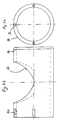
- a first plate 10 preferably a circular plate, is rotatably arranged on the first frame 6, on which a plurality of cylindrical shell-shaped outer shapes 12 of different sizes are arranged on a circle, cf. Fig. 2.
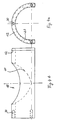
- a second plate 14 preferably a circular plate, is rotatably arranged on the carriage 8, on which a plurality of cylindrical inner forms 16, which are assigned to the outer forms 12 and whose outer diameter is smaller than the inner diameter of the outer forms, are arranged on a circle.
- the outer molds 12 and inner molds 16 can also all be of the same design, and only one outer mold and one inner mold can be provided.
- the inner mold 16 By moving the carriage 8 in the drawing (FIG. 1) to the left, the inner mold 16 can be pushed into the cylindrical shell-shaped outer mold which is open at the bottom in the working position.
- the outer shape is slightly larger than a half-cylinder and has a bending hole 18 in the cylinder jacket, the hole inner edge of which is designed as a bending edge 20 (see also FIG. 4), on which the neck is formed by tightening by means of a stamp, which is explained in more detail below becomes.
- the inner mold 16 is also formed with a hole in the cylinder jacket (see also FIG. 3), which serves as a receptacle 22 for a punch 24, with the aid of which the necking on the tube is formed by tightening on the bending edge 20 of the outer mold 12, which is explained in more detail below.
- a boom 26 for receiving a hydraulic cylinder 28 is arranged on the carriage 8 and actuates the plunger 24 via a device described in more detail below.
- the outer shapes on the slide and the inner shapes can also be arranged in a stationary manner.
- Reference numerals 30 and 32 denote end-face threaded bores in the outer and inner shapes 12 and 16 for fastening to the plates 10 and 14 by means of screw bolts, not shown.
- the stamp 24 is shown in more detail in FIGS. 5a to 5c. It is designed as a hollow body, the outer surface of which is designed as a surface of two vertically intersecting, equally large cylinder surfaces 34, 36, one cylinder surface 34 being arranged vertically and the other cylinder surface 36 being arranged horizontally.
- the cutting edge 38 is rounded, see. in particular Fig. 5a.
- An elongated hole 40 with circular narrow sides 42, 44 is formed in the center of the round cylindrical top 39.
- the elongated hole 40 has an undercut 46 all around. The elongated hole 40 with the undercut 46 serves to receive a locking device, not shown in FIGS. 5a to 5c, described in more detail below with reference to FIGS. 6a and 6b.
- the height of the stamp is chosen to be equal to the radius of the cylinder 36 or somewhat larger than this radius, so that the neck is exactly circular.
- the stamp 24 described has the great advantage that a uniform distribution of the drawing forces on the tubular workpiece is achieved due to its shape, since the stamp always lies everywhere on the workpiece. This avoids the risk of material tearing.
- 6a and 6b show the tool consisting of the inner mold 16, the outer mold 12 and the punch 24 on an actuating device 50.
- the actuating device 50 comprises a locking and unlocking device 52 which is connected via an adapter 54 or also directly to a piston rod of the hydraulic cylinder 28.
- the locking and unlocking device 52 comprises an upwardly semicircular, disk-shaped locking member 56 and two locking elements 58, 60 which, as shown, are preferably in the form of circular disks.
- the locking member 56 is arranged on a rectangular pull rod 62 which is connected to the adapter 54 or the piston rod of the hydraulic cylinder 28 or is screwed, for example, as shown.
- the locking elements 58, 60 are suspended in a pendulum-like manner on a holder 64 by means of integrally formed pendulum rods 66, 68.
- the holder 64 is slidably arranged on the pull rod 62.
- a limiting pin 70 arranged on the pull rod 62 limits the displacement path of the holder 64 on the pull rod 62 downwards.
- the holder 64 is also in a link guide 72
- Unlocking member 74 slidably arranged, which has a guide slot 76 for a flattened guide pin 78 on both sides, which is fixedly arranged in the link guide 72 of the holder 64.
- the unlocking member 74 has inclined surfaces 80, 82 on the top and bottom.
- the guide slot 76 ends at both ends in bores 81, 83, the diameter of which is selected so that rotation of the unlocking member 74 around the guide pin 78 is possible.
- a locking block 84 which is fixedly connected to the latter and which can be displaced along the pull rod 62 and which has a blind hole 86 which preferably points obliquely upwards and into which a locking pin 88 can be inserted, which is attached to the lower end of a locking lever 90 which is connected with its upper end is rotatably arranged on an arm 92 which is fixedly connected to the pull rod 62 or the adapter 54.
- the lower end of the locking lever 90 can additionally have a weight 94 for weighting, which is preferably designed as a handle.
- the punch 24 is placed in the cylindrical inner mold 16 via the receiving hole 22; a tubular workpiece 96, for example a V4a chimney pipe, on which a neck is to be formed, is then pushed over the inner mold 16 in such a way that a hole prefabricated in the workpiece 96 comes to rest over the receiving hole 22; the outer mold 12 is then moved by moving the carriage 8 over the workpiece 96 and the inner mold 16 such that the bending hole 18 of the outer mold is aligned with the hole in the workpiece and the punch in the inner mold.
- This state is shown schematically in FIGS. 1 and 6.
- FIG. 6 shows the device 52 in the partially lowered state, ie in the state in which the locking member 56 and the locking elements 58, 60 are inserted into the punch 24 for locking with the punch.
- the guide pin 78 then enters the respective lower hole (here hole 83) of the unlocking member 74, whereby this unlocking member tilts due to the inclined lower surface 82 with its upper end to the outside. Furthermore, the locking elements 58, 60 move outward on the circular surface of the locking element 56 and under the undercut 46 of the elongated hole 40 of the punch 24. If the pull rod 62 is now moved upwards with the locking element 56, the locking element 56 locks the locking elements 58 and 60 under the undercut 46, which is shown in dashed lines for the locking elements in Fig. 6a. By further pulling up, the punch 24 is taken upwards for bending or flanging the edge of the hole of the tubular workpiece 96 protruding into the bending hole 18 of the outer shape in order to produce a neck.
- the inner mold 16 is pulled out of the workpiece and the outer mold 12 and the pull rod 62 is moved downwards with the aid of the hydraulic cylinder 28 until it is still through the locking member 56 and the locking elements 58 , 60 locked stamp 24 in the inner mold 16 and by further lowering the tie rod 62 and the displacement of the locking member 56 caused by the setting of the link guide 72, the locking elements 58 and 60 can pivot the locking elements back into the 6a shown in solid lines and the locking lever 90 is moved downwards relative to the locking block 84 and automatically locks with its locking pin 88 into the blind bore 86 of the locking block 84.
- the additional weight 94 supports this snapping.
- the locking member 56 and the locking elements 58, 60 can be pulled out of the punch 24 and the inner mold 16 by pulling up the pull rod 62.
- the end of the unlocking member 74, in which the guide pin 78 is located, is taken up by the guide pin 78, and the unlocking member 74 automatically pivots back into the vertical position.
- the device is now ready for the next drawing process.
- neckings can advantageously be produced which have the same diameter as the tubular workpiece.
- the necking can also have a diameter arbitrarily smaller than the diameter of the tubular workpiece.
- the described device 52 for locking and unlocking is suitable not only for punches for producing pipe neckings, but also for punches for producing neckings in other workpieces, for example plate-shaped workpieces.
Landscapes
- Engineering & Computer Science (AREA)
- Mechanical Engineering (AREA)
- Forging (AREA)
- Press Drives And Press Lines (AREA)
- Shaping Metal By Deep-Drawing, Or The Like (AREA)
- Punching Or Piercing (AREA)
- Shaping Of Tube Ends By Bending Or Straightening (AREA)
- Bending Of Plates, Rods, And Pipes (AREA)
Applications Claiming Priority (2)
| Application Number | Priority Date | Filing Date | Title |
|---|---|---|---|
| DE19607311A DE19607311A1 (de) | 1996-02-27 | 1996-02-27 | Vorrichtung zur Herstellung von Aushalsungen in Werkstücken |
| DE19607311 | 1996-02-27 |
Publications (3)
| Publication Number | Publication Date |
|---|---|
| EP0792702A2 true EP0792702A2 (fr) | 1997-09-03 |
| EP0792702A3 EP0792702A3 (fr) | 1997-11-05 |
| EP0792702B1 EP0792702B1 (fr) | 2000-08-16 |
Family
ID=7786551
Family Applications (1)
| Application Number | Title | Priority Date | Filing Date |
|---|---|---|---|
| EP97103051A Expired - Lifetime EP0792702B1 (fr) | 1996-02-27 | 1997-02-26 | Appareil pour la formation de collerette dans des pièces |
Country Status (5)
| Country | Link |
|---|---|
| US (1) | US6021571A (fr) |
| EP (1) | EP0792702B1 (fr) |
| AT (1) | ATE195446T1 (fr) |
| CZ (1) | CZ56697A3 (fr) |
| DE (3) | DE19607311A1 (fr) |
Family Cites Families (11)
| Publication number | Priority date | Publication date | Assignee | Title |
|---|---|---|---|---|
| US2368394A (en) * | 1943-05-03 | 1945-01-30 | Young Radiator Co | Apparatus for flanging openings in tube type headers |
| US2507859A (en) * | 1947-10-13 | 1950-05-16 | Ladish Drop Forge Co | Method of making pipe fittings |
| FR2245431B3 (fr) * | 1973-08-31 | 1980-01-11 | Messer Griesheim Gmbh | |
| DE2511491C2 (de) * | 1975-03-15 | 1983-07-21 | Ing. Edwin Rothenberger Schweisstechnik- U. Industrie-Bedarf, 6000 Frankfurt | Aushalsvorrichtung für das Formen von zylindrischen Ansätzen auf dem Umfang von Rohrleitungen etc. |
| US4106322A (en) * | 1976-09-22 | 1978-08-15 | Evgeny Nikolaevich Moshnin | Press for pressing pipe fittings |
| IT1116912B (it) * | 1977-04-04 | 1986-02-10 | Verrina Spa | Macchina per la formazione di colletti imbutiti in collettori cilindrici di lamiera anche di grande spessore |
| JPS609519A (ja) * | 1983-06-29 | 1985-01-18 | Hitachi Ltd | 分岐管の成形方法 |
| JPS60244422A (ja) * | 1984-05-17 | 1985-12-04 | Hitachi Ltd | 分岐管継手の製造装置 |
| US4676088A (en) * | 1985-06-10 | 1987-06-30 | Hitachi, Ltd. | T-joint manufacturing apparatus |
| DE3744046C2 (de) * | 1987-12-24 | 1994-11-24 | Westaflexwerk Gmbh & Co Kg | Verfahren und Vorrichtung zum Aushalsen von dünnwandigen Blechrohren |
| DE69431869T2 (de) * | 1993-10-06 | 2003-10-02 | Toto Ltd., Kita-Kyushu | Zapfhahn aus rohrmaterial und verfahren zu seiner herstellung |
-
1996
- 1996-02-27 DE DE19607311A patent/DE19607311A1/de not_active Withdrawn
- 1996-07-17 DE DE29612422U patent/DE29612422U1/de not_active Expired - Lifetime
-
1997
- 1997-02-25 CZ CZ97566A patent/CZ56697A3/cs unknown
- 1997-02-26 DE DE59702173T patent/DE59702173D1/de not_active Expired - Lifetime
- 1997-02-26 AT AT97103051T patent/ATE195446T1/de not_active IP Right Cessation
- 1997-02-26 EP EP97103051A patent/EP0792702B1/fr not_active Expired - Lifetime
- 1997-02-26 US US08/804,043 patent/US6021571A/en not_active Expired - Fee Related
Also Published As
| Publication number | Publication date |
|---|---|
| DE29612422U1 (de) | 1996-12-19 |
| US6021571A (en) | 2000-02-08 |
| ATE195446T1 (de) | 2000-09-15 |
| DE19607311A1 (de) | 1997-08-28 |
| DE59702173D1 (de) | 2000-09-21 |
| EP0792702A3 (fr) | 1997-11-05 |
| CZ56697A3 (en) | 1997-11-12 |
| EP0792702B1 (fr) | 2000-08-16 |
Similar Documents
| Publication | Publication Date | Title |
|---|---|---|
| DE3803031B4 (de) | Vorrichtung zur Halterung und Positionierung eines Körpers, der zur Vermessung durch eine Meßvorrichtung vorgesehen ist | |
| DE2732423C3 (de) | Vorrichtung zum Herstellen eines Hulsenteiles | |
| DE2537865C2 (fr) | ||
| WO1993004228A1 (fr) | Procede et dispositif pour la formation de gaines tridimensionnelles | |
| DE2747166C2 (de) | Vorrichtung zum Fließpressen von Ansatzstutzen an einem Rohrkörper | |
| DE69624723T2 (de) | Verfahren und vorrichtung zum schnellwechseln von werkzeugen | |
| DE102016003031A1 (de) | Auswerferpaket mit einem Beschleuniger für Auswerfer | |
| DE2334485A1 (de) | Werkzeugeinsatz, insbesondere fuer stanzpressen | |
| DE1627796A1 (de) | Schiebekopf fuer automatische Montagestrassen | |
| EP0792702B1 (fr) | Appareil pour la formation de collerette dans des pièces | |
| EP0054250A2 (fr) | Dispositif et méthode pour fixer une plaque en métal dur à la tête d'une tarière à spire | |
| EP0322722A2 (fr) | Procédé et appareil pour le formage de collerettes latérales sur des tubes en tôle | |
| DE2536142C3 (de) | Einrichtung zur Handhabung von Rotoren von Elektromotoren und zum Spritzgießen von Aluminiumkäfigwicklungen | |
| DE3234773C2 (de) | Werkzeugablageeinrichtung | |
| DE4129125A1 (de) | Vorrichtung zum krimpfen eines rohrfoermigen metallischen fittings auf das ende eines schlauches | |
| DE3446889C2 (fr) | ||
| DE69024059T2 (de) | Vorrichtung und verfahren zum vorlochen von blöcken. | |
| EP0659538B1 (fr) | Dispositif pour placer des anses sur des récipients | |
| DE879192C (de) | Abgratmaschine | |
| DE1866721U (de) | Vorrichtung zum stanzen bzw. lochen von hohlkoerpern, vornehmlich von rohren. | |
| DE69805213T2 (de) | Stütze für Schalungen | |
| DE2336709B1 (de) | Fallwerk fuer die Schlagpruefung von Schotter u.dgl. | |
| CH278340A (de) | Verfahren zur Herstellung von mit Kopf und Schaft versehenen Gegenständen, insbesondere Schrauben, und Vorrichtung zur Ausübung des Verfahrens. | |
| DE2043855C3 (de) | Werkzeugaufnahme | |
| DE175327C (fr) |
Legal Events
| Date | Code | Title | Description |
|---|---|---|---|
| PUAI | Public reference made under article 153(3) epc to a published international application that has entered the european phase |
Free format text: ORIGINAL CODE: 0009012 |
|
| AK | Designated contracting states |
Kind code of ref document: A2 Designated state(s): AT BE CH DE DK ES FI FR GB GR IE IT LI LU NL PT SE |
|
| AX | Request for extension of the european patent |
Free format text: AL;LT;LV;RO;SI |
|
| PUAL | Search report despatched |
Free format text: ORIGINAL CODE: 0009013 |
|
| AK | Designated contracting states |
Kind code of ref document: A3 Designated state(s): AT BE CH DE DK ES FI FR GB GR IE IT LI LU NL PT SE |
|
| AX | Request for extension of the european patent |
Free format text: AL;LT;LV;RO;SI |
|
| RAP1 | Party data changed (applicant data changed or rights of an application transferred) |
Owner name: WITULSKI, KATHRIN |
|
| 19U | Interruption of proceedings before grant |
Effective date: 19980209 |
|
| 19W | Proceedings resumed before grant after interruption of proceedings |
Effective date: 19980910 |
|
| 17P | Request for examination filed |
Effective date: 19980708 |
|
| 17Q | First examination report despatched |
Effective date: 19981218 |
|
| GRAG | Despatch of communication of intention to grant |
Free format text: ORIGINAL CODE: EPIDOS AGRA |
|
| GRAG | Despatch of communication of intention to grant |
Free format text: ORIGINAL CODE: EPIDOS AGRA |
|
| GRAH | Despatch of communication of intention to grant a patent |
Free format text: ORIGINAL CODE: EPIDOS IGRA |
|
| GRAH | Despatch of communication of intention to grant a patent |
Free format text: ORIGINAL CODE: EPIDOS IGRA |
|
| GRAA | (expected) grant |
Free format text: ORIGINAL CODE: 0009210 |
|
| AK | Designated contracting states |
Kind code of ref document: B1 Designated state(s): AT BE CH DE DK ES FI FR GB GR IE IT LI LU NL PT SE |
|
| PG25 | Lapsed in a contracting state [announced via postgrant information from national office to epo] |
Ref country code: NL Free format text: LAPSE BECAUSE OF FAILURE TO SUBMIT A TRANSLATION OF THE DESCRIPTION OR TO PAY THE FEE WITHIN THE PRESCRIBED TIME-LIMIT Effective date: 20000816 Ref country code: GB Free format text: LAPSE BECAUSE OF FAILURE TO SUBMIT A TRANSLATION OF THE DESCRIPTION OR TO PAY THE FEE WITHIN THE PRESCRIBED TIME-LIMIT Effective date: 20000816 Ref country code: FR Free format text: LAPSE BECAUSE OF FAILURE TO SUBMIT A TRANSLATION OF THE DESCRIPTION OR TO PAY THE FEE WITHIN THE PRESCRIBED TIME-LIMIT Effective date: 20000816 Ref country code: FI Free format text: LAPSE BECAUSE OF FAILURE TO SUBMIT A TRANSLATION OF THE DESCRIPTION OR TO PAY THE FEE WITHIN THE PRESCRIBED TIME-LIMIT Effective date: 20000816 Ref country code: ES Free format text: THE PATENT HAS BEEN ANNULLED BY A DECISION OF A NATIONAL AUTHORITY Effective date: 20000816 |
|
| REF | Corresponds to: |
Ref document number: 195446 Country of ref document: AT Date of ref document: 20000915 Kind code of ref document: T |
|
| REG | Reference to a national code |
Ref country code: CH Ref legal event code: EP |
|
| REG | Reference to a national code |
Ref country code: IE Ref legal event code: FG4D Free format text: GERMAN |
|
| REF | Corresponds to: |
Ref document number: 59702173 Country of ref document: DE Date of ref document: 20000921 |
|
| ITF | It: translation for a ep patent filed | ||
| PG25 | Lapsed in a contracting state [announced via postgrant information from national office to epo] |
Ref country code: SE Free format text: LAPSE BECAUSE OF FAILURE TO SUBMIT A TRANSLATION OF THE DESCRIPTION OR TO PAY THE FEE WITHIN THE PRESCRIBED TIME-LIMIT Effective date: 20001116 Ref country code: PT Free format text: LAPSE BECAUSE OF FAILURE TO SUBMIT A TRANSLATION OF THE DESCRIPTION OR TO PAY THE FEE WITHIN THE PRESCRIBED TIME-LIMIT Effective date: 20001116 Ref country code: DK Free format text: LAPSE BECAUSE OF FAILURE TO SUBMIT A TRANSLATION OF THE DESCRIPTION OR TO PAY THE FEE WITHIN THE PRESCRIBED TIME-LIMIT Effective date: 20001116 |
|
| PG25 | Lapsed in a contracting state [announced via postgrant information from national office to epo] |
Ref country code: GR Free format text: LAPSE BECAUSE OF FAILURE TO SUBMIT A TRANSLATION OF THE DESCRIPTION OR TO PAY THE FEE WITHIN THE PRESCRIBED TIME-LIMIT Effective date: 20001117 |
|
| EN | Fr: translation not filed | ||
| GBV | Gb: ep patent (uk) treated as always having been void in accordance with gb section 77(7)/1977 [no translation filed] |
Effective date: 20000816 |
|
| PG25 | Lapsed in a contracting state [announced via postgrant information from national office to epo] |
Ref country code: LU Free format text: LAPSE BECAUSE OF NON-PAYMENT OF DUE FEES Effective date: 20010226 Ref country code: AT Free format text: LAPSE BECAUSE OF NON-PAYMENT OF DUE FEES Effective date: 20010226 |
|
| PG25 | Lapsed in a contracting state [announced via postgrant information from national office to epo] |
Ref country code: LI Free format text: LAPSE BECAUSE OF NON-PAYMENT OF DUE FEES Effective date: 20010228 Ref country code: CH Free format text: LAPSE BECAUSE OF NON-PAYMENT OF DUE FEES Effective date: 20010228 Ref country code: BE Free format text: LAPSE BECAUSE OF NON-PAYMENT OF DUE FEES Effective date: 20010228 |
|
| PG25 | Lapsed in a contracting state [announced via postgrant information from national office to epo] |
Ref country code: IE Free format text: LAPSE BECAUSE OF NON-PAYMENT OF DUE FEES Effective date: 20010419 |
|
| REG | Reference to a national code |
Ref country code: IE Ref legal event code: FD4D |
|
| PLBE | No opposition filed within time limit |
Free format text: ORIGINAL CODE: 0009261 |
|
| STAA | Information on the status of an ep patent application or granted ep patent |
Free format text: STATUS: NO OPPOSITION FILED WITHIN TIME LIMIT |
|
| 26N | No opposition filed | ||
| BERE | Be: lapsed |
Owner name: WITULSKI KATHRIN Effective date: 20010228 |
|
| REG | Reference to a national code |
Ref country code: CH Ref legal event code: PL |
|
| PGFP | Annual fee paid to national office [announced via postgrant information from national office to epo] |
Ref country code: IT Payment date: 20070607 Year of fee payment: 11 |
|
| PG25 | Lapsed in a contracting state [announced via postgrant information from national office to epo] |
Ref country code: DE Free format text: LAPSE BECAUSE OF NON-PAYMENT OF DUE FEES Effective date: 20070901 |
|
| PGRI | Patent reinstated in contracting state [announced from national office to epo] |
Ref country code: DE Effective date: 20080225 |
|
| PG25 | Lapsed in a contracting state [announced via postgrant information from national office to epo] |
Ref country code: IT Free format text: LAPSE BECAUSE OF NON-PAYMENT OF DUE FEES Effective date: 20080226 |
|
| PGFP | Annual fee paid to national office [announced via postgrant information from national office to epo] |
Ref country code: DE Payment date: 20100831 Year of fee payment: 14 |
|
| REG | Reference to a national code |
Ref country code: DE Ref legal event code: R119 Ref document number: 59702173 Country of ref document: DE Effective date: 20110901 |
|
| PG25 | Lapsed in a contracting state [announced via postgrant information from national office to epo] |
Ref country code: DE Free format text: LAPSE BECAUSE OF NON-PAYMENT OF DUE FEES Effective date: 20110901 |