EP0791714B1 - Scharnier - Google Patents
Scharnier Download PDFInfo
- Publication number
- EP0791714B1 EP0791714B1 EP97101669A EP97101669A EP0791714B1 EP 0791714 B1 EP0791714 B1 EP 0791714B1 EP 97101669 A EP97101669 A EP 97101669A EP 97101669 A EP97101669 A EP 97101669A EP 0791714 B1 EP0791714 B1 EP 0791714B1
- Authority
- EP
- European Patent Office
- Prior art keywords
- hinge
- base plate
- hinge arm
- slide
- arm
- Prior art date
- Legal status (The legal status is an assumption and is not a legal conclusion. Google has not performed a legal analysis and makes no representation as to the accuracy of the status listed.)
- Expired - Lifetime
Links
Images


Classifications
-
- E—FIXED CONSTRUCTIONS
- E05—LOCKS; KEYS; WINDOW OR DOOR FITTINGS; SAFES
- E05D—HINGES OR SUSPENSION DEVICES FOR DOORS, WINDOWS OR WINGS
- E05D7/00—Hinges or pivots of special construction
- E05D7/12—Hinges or pivots of special construction to allow easy detachment of the hinge from the wing or the frame
- E05D7/123—Hinges or pivots of special construction to allow easy detachment of the hinge from the wing or the frame specially adapted for cabinets or furniture
-
- E—FIXED CONSTRUCTIONS
- E05—LOCKS; KEYS; WINDOW OR DOOR FITTINGS; SAFES
- E05Y—INDEXING SCHEME ASSOCIATED WITH SUBCLASSES E05D AND E05F, RELATING TO CONSTRUCTION ELEMENTS, ELECTRIC CONTROL, POWER SUPPLY, POWER SIGNAL OR TRANSMISSION, USER INTERFACES, MOUNTING OR COUPLING, DETAILS, ACCESSORIES, AUXILIARY OPERATIONS NOT OTHERWISE PROVIDED FOR, APPLICATION THEREOF
- E05Y2600/00—Mounting or coupling arrangements for elements provided for in this subclass
- E05Y2600/50—Mounting methods; Positioning
- E05Y2600/52—Toolless
- E05Y2600/53—Snapping
-
- E—FIXED CONSTRUCTIONS
- E05—LOCKS; KEYS; WINDOW OR DOOR FITTINGS; SAFES
- E05Y—INDEXING SCHEME ASSOCIATED WITH SUBCLASSES E05D AND E05F, RELATING TO CONSTRUCTION ELEMENTS, ELECTRIC CONTROL, POWER SUPPLY, POWER SIGNAL OR TRANSMISSION, USER INTERFACES, MOUNTING OR COUPLING, DETAILS, ACCESSORIES, AUXILIARY OPERATIONS NOT OTHERWISE PROVIDED FOR, APPLICATION THEREOF
- E05Y2900/00—Application of doors, windows, wings or fittings thereof
- E05Y2900/20—Application of doors, windows, wings or fittings thereof for furniture, e.g. cabinets
Definitions
- the invention relates to a hinge with a on a base plate mounted hinge arm, the at least one hinge axis with a on a furniture door fastened stop member, such as a hinge cup is rotatably connected, wherein the base plate and / or the hinge arm with vertical are provided to the mounting surface protruding mounting pins, the Having notches and the hinge arm by means of a spring acted upon Slider, which has a handle portion and which is movable parallel to the base plate and engages in the notches of the mounting pins, can be locked to the base plate, wherein the base plate and the hinge arm in plan view rectangular with two longer ones and two shorter sides are executed.
- EP A 0 256 376 is a hinge with a on a furniture side wall to fixing hinge arm known.
- the attachment of the hinge arm takes place by means of a base plate and an intermediate piece.
- In the intermediate piece stores Slider with hooks directed towards the base through openings in the Protect the base plate and engage in this.
- the invention relates to a hinge in which the hinge arm attachable to a furniture frame.
- the object of the invention is to provide a hinge in which the hinge arm Quickly and without tools on the base plate both mounted and dismounted can be, with the hinge not on a furniture sidewall but on a To attach to a furniture side wall connected frame.
- the object of the invention is by the features of claim 1 solved, where mainly the base plate at least one of the longer sides one from the base plate at right angles protruding side bar and the slider two at right angles to each other standing arms, which engage at the notches of the mounting pins, wherein the Handle part of the slider also on one of the longer sides of the base plate and the Hinge arm is arranged.
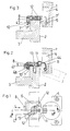
- hinge according to the invention can be a door 1 to a furniture frame. 2 be attached, which covers a furniture side wall 3 at the end.
- a hinge cup 4 is in a conventional manner in a hole in the door 1 used and has an axis of rotation 5, via which he with the hinge arm. 6 connected is.
- the hinge arm 6 by means of a slide 8 designed as a latch member on a base plate 7 anchored.
- the base plate 7 is by means of a screw 13 on the furniture frame. 2 attached.
- the base plate 7 is designed in cross-section U-shaped and surrounds the Furniture frame 2 on three sides, with two side legs 7 'at the Front and at the back of the furniture frame 2 rests.
- the hinge arm 6 has a rear edge web 43, with which he in a Intermediate plate 10 is mounted.
- the intermediate plate 10 On the side facing the hinge axis 5 side is the intermediate plate 10 provided with a slot into which a Fugenverstellschraube 11 is mounted.
- the joint adjustment screw 11 is stored in a female thread 44 in Hinge arm 6.
- the slider 8 is located between the intermediate plate 10 and the hinge arm 6th
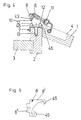
- the base plate 7 has two mounting pins 12 and the slider 8 is with two hooks 45 provided with which he in notches 46 in the mounting pin 12 engages.
- the hooks 45 are directed against each other and include the Mounting pin 12.
- the slider 8 is executed in a rough outline triangular and has two mutually perpendicular arms 8 ', which are parallel to two perpendicular side edges of the base plate 7 extend.
- the slider 8 is acted upon by a spring 9, the slider 8 in the Locking position, that is in the notches 46 of the mounting pin 12 presses. These Locking position is shown in Figs. 1 and 3.
- the slider 8 in this case has an angled web 47. Between this Angled web 47 and an angled web 48 of the intermediate plate 10th is the spring 9.
- the joint adjustment screw 15 stores in a nut thread 47 of the hinge arm. 6 and protrudes through a slot 48 in the arm 16.
- the arm 16 is through the joint adjustment screw 15 clamped on the hinge arm 6 and is over the length of the Langloches 48 adjustable in the direction of the furniture sluice.
- the hinge arm 6 in turn has an angled edge web 43, with which he is suspended in an intermediate plate 10. At the hinge axis facing Side of the hinge arm 6 projects the intermediate plate 10 with projections 50 in Slots in the hinge arm 6, whereby the hinge arm 6 with the intermediate plate 10th connected is.
- the slider 8 has two arms 8 ', 8' ', which in the locking position directly in the Notches 46 protrude into the mounting pins 12.
- the slider 8 is against the pressure of the spring 9 in the height of the furniture frame. 2 displaceable, wherein the slide 8 in turn has an angled web 47, which serves as a handle and over which the slider 8 is slidable.
- the spring 9 is located between the web 8 '' of the slider 8, at the edge it rests, and a Stop edge on the base plate 7.
- the spring 9 is again to a compression spring.
- the base plate 7 is in turn by means of a screw 13 on the furniture frame. 2 attached.
- the screw 13 protrudes through a slot 51 in the base plate 7, so that the base plate 7 can be moved over the height of the elongated hole 51 and a height adjustment of the hinge arm 6 is possible.
- the hinge arm 6 with the Attachment pin 12 provided.
- the arm 16, which on the hinge arm 5 is hinged, in turn, by means of a joint adjustment screw 15 with the rest Hinge arm 6 connected.
- the mounting pins 12 protrude through holes 17 in the base plate 7.
- Below the base plate 7, the slider 8 is arranged, the like in the embodiment described above, two arms 8 ', 8' 'has.
- a compression spring 9 which in a is located within a recess 19 of the slider 8.
- the slider 8 is vertical to the hinge axis 15 and the closing plane of the door leaf 1 movable.
- FIG. 17 shows the locking position of the slider 8, wherein the arms 8 ', 8' 'in the notches 46 of Engage attachment pin 12.
- the slider 8 is provided with an angled web 18, which has a handle forms. If the slider 8 against the pressure of the spring 9 from the in Fig. 19 in moves the position shown in FIG. 20, the slider 8 snaps out of his Anchoring in the mounting pin 12, and the hinge arm 6 can from the Base plate 7 are lifted.
Landscapes
- Engineering & Computer Science (AREA)
- Mechanical Engineering (AREA)
- Hinges (AREA)
Description
Claims (6)
- Scharnier mit einem auf einer Grundplatte (7) gelagerten Scharnierarm (6), der über mindestens eine Scharnierachse (5) mit einem an einer Möbeltüre befestigbaren Anschlagteil (4), beispielsweise einem Scharniertopf drehbar verbunden ist, wobei die Grundplatte (7) und/oder der Scharnierarm (6) mit senkrecht zur Montagefläche abstehenden Befestigungszapfen (12) versehen sind, die Kerben (46) aufweisen und der Scharnierarm (6) mittels eines von einer Feder (9) beaufschlagten Schiebers (8), der einen Griffteil (18, 47) aufweist und der parallel zur Grundplatte (7) bewegbar ist und in den Kerben (46) der Befestigungszapfen (12) eingreift, an der Grundplatte (7) arretierbar ist, wobei die Grundplatte (7) und der Scharnierarm (6) in Draufsicht rechteckig mit zwei längeren und zwei kürzeren Seiten ausgeführt sind, dadurch gekennzeichnet, daß die längeren Seiten des Sharnierarmes (6) und der Grundplatte (7) parallel zur Scharnierachse (5) ausgerichtet sind, die Grundplatte (7) an mindestens einer der längeren Seiten einen von der Grundplatte (7) im rechten Winkel abstehenden Seitensteg (7') aufweist , der in Montagelage an einer zur Ebene der geschlossenen Möbeltüre parallelen Seite eines Möbelrahmens (2) anliegt und daß der Schieber (8) zwei im rechten Winkel zueinander stehende Arme (8', 8"), die bei den Kerben (46) der Befestigungszapfen (12) einrasten, aufweist, wobei der Griffteil (18, 47) des Schiebers (8) ebenfalls an einer der längeren Seiten der Grundplatte (7) und des Scharnierarmes (6) angeordnet ist.
- Scharnier nach Anspruch 1, dadurch gekennzeichnet, daß an den Armen (8', 8") des Schiebers (8) zwei einander entgegen gerichtete Haken (45) ausgebildet sind, die bei den Kerben (46) der Befestigungszapfen (12) einrasten.
- Scharnier nach Anspruch 1 oder 2, dadurch gekennzeichnet, daß der Schieber (8) an einem Rand eine Aussparung (19) aufweist, innerhalb der sich die Feder (9) befindet.
- Scharnier nach einem der Ansprüche 1 bis 3, dadurch gekennzeichnet, daß der Scharnierarm (6) einen abgewinkelten Randsteg (43) aufweist, mit dem er in eine zwischen dem Scharnierarm (6) und der Grundplatte (7) angeordnete Zwischenplatte (10) eingehängt ist.
- Scharnier nach Anspruch 4, dadurch gekennzeichnet, daß in die Zwischenplatte (10) an ihrer der Scharnierachse (5) zugewendeten Seite eine Fugenverstellschraube (11) eingehängt ist, die in einem Muttergewinde (44) des Scharnierarmes (6) lagert.
- Scharnier nach Anspruch 3, dadurch gekennzeichnet, daß die Feder (9) eine Druckfeder ist.
Applications Claiming Priority (3)
| Application Number | Priority Date | Filing Date | Title |
|---|---|---|---|
| AT25796 | 1996-02-14 | ||
| AT25796 | 1996-02-14 | ||
| AT257/96 | 1996-02-14 |
Publications (2)
| Publication Number | Publication Date |
|---|---|
| EP0791714A1 EP0791714A1 (de) | 1997-08-27 |
| EP0791714B1 true EP0791714B1 (de) | 2005-12-21 |
Family
ID=3485741
Family Applications (1)
| Application Number | Title | Priority Date | Filing Date |
|---|---|---|---|
| EP97101669A Expired - Lifetime EP0791714B1 (de) | 1996-02-14 | 1997-02-04 | Scharnier |
Country Status (4)
| Country | Link |
|---|---|
| US (1) | US5819371A (de) |
| EP (1) | EP0791714B1 (de) |
| AT (2) | ATE313679T1 (de) |
| DE (1) | DE59712527D1 (de) |
Families Citing this family (11)
| Publication number | Priority date | Publication date | Assignee | Title |
|---|---|---|---|---|
| IT1289043B1 (it) * | 1996-12-20 | 1998-09-25 | Top Sedia Spa | Sistema di assemblaggio ante e/o fasce di completamento per mobili componibili |
| DE20009317U1 (de) * | 2000-05-24 | 2000-08-17 | Arturo Salice S.P.A., Novedrate, Como | Befestigungsplatte zur Befestigung eines Scharnierarmes eines Möbelscharniers |
| DE10209135B4 (de) * | 2001-03-30 | 2010-12-02 | Eku Ag | Laufwerkanordnung für Schiebetür |
| US6732976B2 (en) * | 2001-08-01 | 2004-05-11 | Goodrich Hella Aerospace Lighting Systems Gmbh | Device for fastening a first part to a second part |
| US6647591B1 (en) * | 2002-07-01 | 2003-11-18 | Grass America Inc. | Low profile, partial door overlay hinge |
| US6810563B1 (en) * | 2002-11-04 | 2004-11-02 | Grass America Inc. | Mounting plate for a furniture hinge |
| GB0621105D0 (en) * | 2006-10-24 | 2006-12-06 | Window Fab & Fixing Supplies | Hinge |
| CN102536018B (zh) * | 2010-12-30 | 2014-07-23 | 昆山湖华金属制品有限公司 | 铰链 |
| US9565941B2 (en) * | 2014-05-21 | 2017-02-14 | Grass America, Inc. | Hinge locking member |
| AT523411B1 (de) * | 2020-01-17 | 2021-08-15 | Blum Gmbh Julius | Scharnieranordnung |
| AT523441B1 (de) * | 2020-01-17 | 2023-05-15 | Blum Gmbh Julius | Scharnieranordnung |
Citations (1)
| Publication number | Priority date | Publication date | Assignee | Title |
|---|---|---|---|---|
| US4654932A (en) * | 1983-12-30 | 1987-04-07 | Julius Blum Gesellschaft M.B.H. | Hinge |
Family Cites Families (12)
| Publication number | Priority date | Publication date | Assignee | Title |
|---|---|---|---|---|
| US2131802A (en) * | 1935-10-18 | 1938-10-04 | L C Smith & Corona Typewriters | Separable hinge connection |
| AT366464B (de) * | 1976-09-02 | 1982-04-13 | Grass Alfred Metallwaren | Einstellbarer scharnierarm eines tuer- oder moebelscharniers |
| DE3161939D1 (en) * | 1980-07-15 | 1984-02-23 | Salice Arturo Spa | Hinge arm with mounting plate |
| DE3587560D1 (de) * | 1984-10-19 | 1993-10-07 | Blum Gmbh Julius | Scharnier. |
| DE3627170C1 (de) * | 1986-08-11 | 1988-03-24 | Salice Arturo Spa | Scharnierarm fuer ein Moebelscharnier o.dgl.,mit Grundplatte direkt oder indirekt verbindbar |
| AT391344B (de) * | 1987-08-31 | 1990-09-25 | Blum Gmbh Julius | Scharnier |
| DE68914595T2 (de) * | 1988-11-16 | 1994-08-25 | Franco Ferrari | Türscharnier mit Schnellkupplung. |
| ES1009089Y (es) * | 1989-02-17 | 1989-12-16 | Blanco Eguiluz M. Begona | Dispositivo de enganche rapido para bisagras de muebles. |
| US5088155A (en) * | 1990-09-07 | 1992-02-18 | Grass Ag | Door hinge with resiliently biased retaining means |
| DE4031305A1 (de) * | 1990-10-04 | 1992-04-09 | Lautenschlaeger Kg Karl | Moebelscharnier |
| AT399534B (de) * | 1993-02-22 | 1995-05-26 | Blum Gmbh Julius | Grundplatte für ein scharnier |
| US5577296A (en) * | 1993-10-19 | 1996-11-26 | Grass Ag | Door hinge with snap-in locking device for quick assembly |
-
1997
- 1997-02-04 AT AT97101669T patent/ATE313679T1/de not_active IP Right Cessation
- 1997-02-04 DE DE59712527T patent/DE59712527D1/de not_active Expired - Lifetime
- 1997-02-04 EP EP97101669A patent/EP0791714B1/de not_active Expired - Lifetime
- 1997-02-13 US US08/800,281 patent/US5819371A/en not_active Expired - Lifetime
- 1997-03-25 AT AT0802297U patent/AT1732U1/de not_active IP Right Cessation
Patent Citations (1)
| Publication number | Priority date | Publication date | Assignee | Title |
|---|---|---|---|---|
| US4654932A (en) * | 1983-12-30 | 1987-04-07 | Julius Blum Gesellschaft M.B.H. | Hinge |
Also Published As
| Publication number | Publication date |
|---|---|
| US5819371A (en) | 1998-10-13 |
| ATE313679T1 (de) | 2006-01-15 |
| DE59712527D1 (de) | 2006-01-26 |
| AT1732U1 (de) | 1997-10-27 |
| EP0791714A1 (de) | 1997-08-27 |
Similar Documents
| Publication | Publication Date | Title |
|---|---|---|
| EP0269701B1 (de) | Möbelscharnier | |
| WO1986002402A1 (fr) | Articulation a charniere | |
| AT391162B (de) | Scharnier | |
| DE202004000652U1 (de) | Scharnier | |
| DE3448346C2 (de) | ||
| DE29522288U1 (de) | Möbelscharnier | |
| AT402527B (de) | Scharnier | |
| EP1030021A2 (de) | Scharnier | |
| DE8632799U1 (de) | Scharnier | |
| DE3733188C2 (de) | Abdeckkappe für ein Möbelscharnier | |
| EP0791714A1 (de) | Scharnier | |
| DE3435009C2 (de) | Türhalter für Fahrzeugtüren | |
| DE60304682T2 (de) | Scharnier für möbel | |
| EP1066440B1 (de) | Montageplatte für möbelscharniere | |
| EP0478639A1 (de) | Scharnier. | |
| DE3630446C2 (de) | Möbelscharnier | |
| DE8907480U1 (de) | Montageplatte für Möbelscharniere | |
| EP0340456A1 (de) | Scherenlager eines Dreh-Kipp-Beschlags | |
| EP0457170B1 (de) | Scharnier | |
| DE4236879C2 (de) | Eingelenk-Möbelscharnier | |
| DE202018006086U1 (de) | Aufhängevorrichtung für Möbel | |
| EP0392570B1 (de) | Scharnier | |
| DE3913319C2 (de) | ||
| AT393867B (de) | Moebelscharnier | |
| DE2524454B2 (de) | Scharnier, für rahmenlose Türen aus Glas |
Legal Events
| Date | Code | Title | Description |
|---|---|---|---|
| PUAI | Public reference made under article 153(3) epc to a published international application that has entered the european phase |
Free format text: ORIGINAL CODE: 0009012 |
|
| AK | Designated contracting states |
Kind code of ref document: A1 Designated state(s): AT DE ES IT |
|
| 17P | Request for examination filed |
Effective date: 19980226 |
|
| 17Q | First examination report despatched |
Effective date: 19990219 |
|
| GRAP | Despatch of communication of intention to grant a patent |
Free format text: ORIGINAL CODE: EPIDOSNIGR1 |
|
| GRAS | Grant fee paid |
Free format text: ORIGINAL CODE: EPIDOSNIGR3 |
|
| GRAA | (expected) grant |
Free format text: ORIGINAL CODE: 0009210 |
|
| RAP1 | Party data changed (applicant data changed or rights of an application transferred) |
Owner name: JULIUS BLUM GMBH |
|
| AK | Designated contracting states |
Kind code of ref document: B1 Designated state(s): AT DE ES IT |
|
| REF | Corresponds to: |
Ref document number: 59712527 Country of ref document: DE Date of ref document: 20060126 Kind code of ref document: P |
|
| PG25 | Lapsed in a contracting state [announced via postgrant information from national office to epo] |
Ref country code: AT Free format text: LAPSE BECAUSE OF NON-PAYMENT OF DUE FEES Effective date: 20060204 |
|
| PG25 | Lapsed in a contracting state [announced via postgrant information from national office to epo] |
Ref country code: ES Free format text: LAPSE BECAUSE OF FAILURE TO SUBMIT A TRANSLATION OF THE DESCRIPTION OR TO PAY THE FEE WITHIN THE PRESCRIBED TIME-LIMIT Effective date: 20060401 |
|
| PLBE | No opposition filed within time limit |
Free format text: ORIGINAL CODE: 0009261 |
|
| STAA | Information on the status of an ep patent application or granted ep patent |
Free format text: STATUS: NO OPPOSITION FILED WITHIN TIME LIMIT |
|
| 26N | No opposition filed |
Effective date: 20060922 |
|
| PGFP | Annual fee paid to national office [announced via postgrant information from national office to epo] |
Ref country code: IT Payment date: 20150220 Year of fee payment: 19 |
|
| PGFP | Annual fee paid to national office [announced via postgrant information from national office to epo] |
Ref country code: DE Payment date: 20150429 Year of fee payment: 19 |
|
| REG | Reference to a national code |
Ref country code: DE Ref legal event code: R119 Ref document number: 59712527 Country of ref document: DE |
|
| PG25 | Lapsed in a contracting state [announced via postgrant information from national office to epo] |
Ref country code: IT Free format text: LAPSE BECAUSE OF NON-PAYMENT OF DUE FEES Effective date: 20160204 |
|
| PG25 | Lapsed in a contracting state [announced via postgrant information from national office to epo] |
Ref country code: DE Free format text: LAPSE BECAUSE OF NON-PAYMENT OF DUE FEES Effective date: 20160901 |