EP0790174A2 - Mit Muskelkraft betreibares Fahrzeug - Google Patents
Mit Muskelkraft betreibares Fahrzeug Download PDFInfo
- Publication number
- EP0790174A2 EP0790174A2 EP97102301A EP97102301A EP0790174A2 EP 0790174 A2 EP0790174 A2 EP 0790174A2 EP 97102301 A EP97102301 A EP 97102301A EP 97102301 A EP97102301 A EP 97102301A EP 0790174 A2 EP0790174 A2 EP 0790174A2
- Authority
- EP
- European Patent Office
- Prior art keywords
- motor
- low speed
- electric motor
- low
- range
- Prior art date
- Legal status (The legal status is an assumption and is not a legal conclusion. Google has not performed a legal analysis and makes no representation as to the accuracy of the status listed.)
- Granted
Links
Images



Classifications
-
- B—PERFORMING OPERATIONS; TRANSPORTING
- B62—LAND VEHICLES FOR TRAVELLING OTHERWISE THAN ON RAILS
- B62M—RIDER PROPULSION OF WHEELED VEHICLES OR SLEDGES; POWERED PROPULSION OF SLEDGES OR SINGLE-TRACK CYCLES; TRANSMISSIONS SPECIALLY ADAPTED FOR SUCH VEHICLES
- B62M6/00—Rider propulsion of wheeled vehicles with additional source of power, e.g. combustion engine or electric motor
- B62M6/40—Rider propelled cycles with auxiliary electric motor
- B62M6/45—Control or actuating devices therefor
-
- B—PERFORMING OPERATIONS; TRANSPORTING
- B60—VEHICLES IN GENERAL
- B60L—PROPULSION OF ELECTRICALLY-PROPELLED VEHICLES; SUPPLYING ELECTRIC POWER FOR AUXILIARY EQUIPMENT OF ELECTRICALLY-PROPELLED VEHICLES; ELECTRODYNAMIC BRAKE SYSTEMS FOR VEHICLES IN GENERAL; MAGNETIC SUSPENSION OR LEVITATION FOR VEHICLES; MONITORING OPERATING VARIABLES OF ELECTRICALLY-PROPELLED VEHICLES; ELECTRIC SAFETY DEVICES FOR ELECTRICALLY-PROPELLED VEHICLES
- B60L15/00—Methods, circuits, or devices for controlling the traction-motor speed of electrically-propelled vehicles
- B60L15/20—Methods, circuits, or devices for controlling the traction-motor speed of electrically-propelled vehicles for control of the vehicle or its driving motor to achieve a desired performance, e.g. speed, torque, programmed variation of speed
-
- B—PERFORMING OPERATIONS; TRANSPORTING
- B60—VEHICLES IN GENERAL
- B60L—PROPULSION OF ELECTRICALLY-PROPELLED VEHICLES; SUPPLYING ELECTRIC POWER FOR AUXILIARY EQUIPMENT OF ELECTRICALLY-PROPELLED VEHICLES; ELECTRODYNAMIC BRAKE SYSTEMS FOR VEHICLES IN GENERAL; MAGNETIC SUSPENSION OR LEVITATION FOR VEHICLES; MONITORING OPERATING VARIABLES OF ELECTRICALLY-PROPELLED VEHICLES; ELECTRIC SAFETY DEVICES FOR ELECTRICALLY-PROPELLED VEHICLES
- B60L50/00—Electric propulsion with power supplied within the vehicle
- B60L50/20—Electric propulsion with power supplied within the vehicle using propulsion power generated by humans or animals
-
- B—PERFORMING OPERATIONS; TRANSPORTING
- B60—VEHICLES IN GENERAL
- B60L—PROPULSION OF ELECTRICALLY-PROPELLED VEHICLES; SUPPLYING ELECTRIC POWER FOR AUXILIARY EQUIPMENT OF ELECTRICALLY-PROPELLED VEHICLES; ELECTRODYNAMIC BRAKE SYSTEMS FOR VEHICLES IN GENERAL; MAGNETIC SUSPENSION OR LEVITATION FOR VEHICLES; MONITORING OPERATING VARIABLES OF ELECTRICALLY-PROPELLED VEHICLES; ELECTRIC SAFETY DEVICES FOR ELECTRICALLY-PROPELLED VEHICLES
- B60L50/00—Electric propulsion with power supplied within the vehicle
- B60L50/50—Electric propulsion with power supplied within the vehicle using propulsion power supplied by batteries or fuel cells
- B60L50/53—Electric propulsion with power supplied within the vehicle using propulsion power supplied by batteries or fuel cells in combination with an external power supply, e.g. from overhead contact lines
-
- B—PERFORMING OPERATIONS; TRANSPORTING
- B62—LAND VEHICLES FOR TRAVELLING OTHERWISE THAN ON RAILS
- B62M—RIDER PROPULSION OF WHEELED VEHICLES OR SLEDGES; POWERED PROPULSION OF SLEDGES OR SINGLE-TRACK CYCLES; TRANSMISSIONS SPECIALLY ADAPTED FOR SUCH VEHICLES
- B62M6/00—Rider propulsion of wheeled vehicles with additional source of power, e.g. combustion engine or electric motor
- B62M6/40—Rider propelled cycles with auxiliary electric motor
- B62M6/55—Rider propelled cycles with auxiliary electric motor power-driven at crank shafts parts
-
- B—PERFORMING OPERATIONS; TRANSPORTING
- B60—VEHICLES IN GENERAL
- B60L—PROPULSION OF ELECTRICALLY-PROPELLED VEHICLES; SUPPLYING ELECTRIC POWER FOR AUXILIARY EQUIPMENT OF ELECTRICALLY-PROPELLED VEHICLES; ELECTRODYNAMIC BRAKE SYSTEMS FOR VEHICLES IN GENERAL; MAGNETIC SUSPENSION OR LEVITATION FOR VEHICLES; MONITORING OPERATING VARIABLES OF ELECTRICALLY-PROPELLED VEHICLES; ELECTRIC SAFETY DEVICES FOR ELECTRICALLY-PROPELLED VEHICLES
- B60L2200/00—Type of vehicles
- B60L2200/12—Bikes
-
- Y—GENERAL TAGGING OF NEW TECHNOLOGICAL DEVELOPMENTS; GENERAL TAGGING OF CROSS-SECTIONAL TECHNOLOGIES SPANNING OVER SEVERAL SECTIONS OF THE IPC; TECHNICAL SUBJECTS COVERED BY FORMER USPC CROSS-REFERENCE ART COLLECTIONS [XRACs] AND DIGESTS
- Y02—TECHNOLOGIES OR APPLICATIONS FOR MITIGATION OR ADAPTATION AGAINST CLIMATE CHANGE
- Y02T—CLIMATE CHANGE MITIGATION TECHNOLOGIES RELATED TO TRANSPORTATION
- Y02T10/00—Road transport of goods or passengers
- Y02T10/60—Other road transportation technologies with climate change mitigation effect
- Y02T10/64—Electric machine technologies in electromobility
-
- Y—GENERAL TAGGING OF NEW TECHNOLOGICAL DEVELOPMENTS; GENERAL TAGGING OF CROSS-SECTIONAL TECHNOLOGIES SPANNING OVER SEVERAL SECTIONS OF THE IPC; TECHNICAL SUBJECTS COVERED BY FORMER USPC CROSS-REFERENCE ART COLLECTIONS [XRACs] AND DIGESTS
- Y02—TECHNOLOGIES OR APPLICATIONS FOR MITIGATION OR ADAPTATION AGAINST CLIMATE CHANGE
- Y02T—CLIMATE CHANGE MITIGATION TECHNOLOGIES RELATED TO TRANSPORTATION
- Y02T10/00—Road transport of goods or passengers
- Y02T10/60—Other road transportation technologies with climate change mitigation effect
- Y02T10/70—Energy storage systems for electromobility, e.g. batteries
-
- Y—GENERAL TAGGING OF NEW TECHNOLOGICAL DEVELOPMENTS; GENERAL TAGGING OF CROSS-SECTIONAL TECHNOLOGIES SPANNING OVER SEVERAL SECTIONS OF THE IPC; TECHNICAL SUBJECTS COVERED BY FORMER USPC CROSS-REFERENCE ART COLLECTIONS [XRACs] AND DIGESTS
- Y02—TECHNOLOGIES OR APPLICATIONS FOR MITIGATION OR ADAPTATION AGAINST CLIMATE CHANGE
- Y02T—CLIMATE CHANGE MITIGATION TECHNOLOGIES RELATED TO TRANSPORTATION
- Y02T10/00—Road transport of goods or passengers
- Y02T10/60—Other road transportation technologies with climate change mitigation effect
- Y02T10/72—Electric energy management in electromobility
Definitions
- This invention relates to a muscle-operated vehicle, in particular bicycle, provided with a human power drive system comprising a crankshaft, an auxiliary power unit comprising a battery powered electric motor, and with a control device for controlling the auxiliary power unit in accordance with the power applicable to the human power drive system and to a method of controlling an auxiliary power of a muscle-operated vehicle, in particular bicycle, provided with a human power drive system comprising a crankshaft, an auxiliary power unit comprising a battery powered electric motor for providing said auxiliary power, and with a control device controlling the auxiliary power unit in accordance with the power supplied to said human power drive system.
- motor-assisted bicycles are drawing public attention in which the pedal force applied on the pedals and assist power of an electric motor are combined and transmitted to the driving wheel.
- Such motor-assisted bicycles are constituted that the assist power is supplied according to the pedal force. That is to say, no assist power is provided unless the pedal force is applied. Therefore, when the rider is compelled to push and roll the bicycle uphill because the grade is so steep that the rider cannot ride and run uphill even if the assist power is provided, no assist power is provided, and the rider is required of a greater effort because of an additional weight of the bicycle.
- the motor is generally of a high speed type to obtain an optimum energy efficiency at high speeds, problems arise that, when the motor is used at very low speeds, energy efficiency lowers, the battery power is rapidly consumed, and the cruising range decreases. If a low speed type of motor is used which has a high efficiency at low speeds on the other hand, the motor rotation cannot catch up the ordinary running speed of the vehicle.
- control device comprising motor characteristic control means for changing the operation characteristic of the electric motor in accordance with vehicle running conditions detected.
- the output of the electric motor is controllable by the control device in accordance with the force or torque, respectively, applicable to the crankshaft and/or the rotational speed of said crankshaft.
- an electric motor is a permanent magnet field type DC motor.
- said control means is adapted to apply an electric current to commutating pole coils disposed around a permanent magnet in a direction to alter the magnetic field in accordance with the vehicle running conditions detected.
- this objective is solved for a method as indicated above comprising the steps of detecting vehicle running conditions and controlling the operation characteristic of the electric motor in accordance with said detected vehicle running conditions.
- said vehicle running conditions are the force or torque, respectively, applied to the crankshaft and/or the rotational speed of the crankshaft, because these conditions are easy to detect.
- the electric motor is a permanent magnet field type DC motor and the control means applies an electric current to commutating pole coils disposed around a permanent magnet in a direction to alter the magnetic field in accordance with the vehicle running conditions detected.
- the control device is provided with a map in which the operation range for the electric motor is divided according to the motor rotation speed and the output torque into a low speed high torque range, a low speed low torque range and a high speed low torque range, said control device determines and detects the actual operation range of the electric motor and controls the electrical current application in accordance with the detected results.
- FIGs. 1 to 5 are for describing a motor drive device for a motor-assisted bicycle as an embodiment of the invention.
- FIG. 1 is a side view of the motor-assisted bicycle.
- FIG. 2 shows a cross section of an electric motor.
- FIG. 3 shows a constitution of a motor control device.
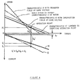
- FIG. 4 is a characteristic diagram for describing effect of decrease in necessary current.
- FIG. 5 is a characteristic diagram for describing operation ranges.
- FIG. 1 shows a motor-assisted bicycle 1.
- a body frame 10 of the bicycle 1 comprises a head pipe 12, a down tube 14 extending from the head pipe 12 obliquely rear downward, a seat tube 16 rising from the rear part of the down tube 14, paired right and left rear arms 20 extending from the rear end of the down tube 14, and paired right and left seat stays 22 making connection between the rear ends of the rear arms 20 and the top end of the seat tube 16.
- a front fork 24 is bearing-supported to be freely turned right and left on the head pipe 12.
- a front wheel is bearing-supported at the lower end of the front fork 24.
- a seat post 30a is inserted in the seat tube 16 so as to be adjustable in height.
- a saddle 30 is attached to the top end of the seat post 30a.
- a rear wheel 32 is rotatably disposed between the rear ends of the rear arms 20.
- the symbol 40 denotes a power unit as the power source of the bicycle 1, comprising; a power case 42 housing a driving mechanism, and an electric motor 44 disposed in a vehicle body cover 41 so as to project obliquely up forward from the power case 42.
- the power case 42 is attached below the rear portion 14a of the down tube 14.
- the electric motor 44 lies parallel to the rear portion 14a of the down tube 14.
- a battery 64 to be the power source for the power unit 40 comprises a large number of battery cells connected in series and housed in a case, and is removably housed in a battery case 60 disposed in the space between the seat tube 16 and the front edge of the rear wheel 32.
- the top end opening of the battery case 60 is located between and projects upward from the right and left seat stays 22 so that the battery 64 may be installed and removed in vertical directions.
- crankshaft 46 passes through the power case 42 in the vehicle width direction.
- Crank arms 48 (only one is shown) are attached to both ends of the crankshaft 46.
- Each of the crank arms 48 is provided with a crank pedal 50.
- a human power drive system 75 is constituted in which the pedal force applied to the crank pedals 50 is transmitted through a chain 52 to the rear wheel 32.
- the pedal force applied to the crank pedals 50 is detected with a pedal force sensor disposed in the power case 42.
- the output of the electric motor 44 (assist power) is controlled with a controller 54 according to the pedal force and the rotation speed of the crankshaft.
- an electric power drive system is constituted in which an assist power commensurate with the pedal force is transmitted to the rear wheel 32.
- the controller 54 for controlling the output from the motor 44 is attached inside the vehicle body cover 41 so as to be located below the front portion 14b of the down tube 14.
- a main switch 56 and a self-propelling switch 63 for selecting a very low speed running mode are disposed in the area where the vehicle body frame 10 is connected to the head pipe 12.
- the main switch 56 and the self-propelled run selecting switch 63 are disposed at an opening 41a made in the vehicle body cover 41 so as to be accessible from outside.
- the electric motor 44 is of a permanent magnet field type DC motor in which a core (rotor) 82 with an armature coil wound around an armature core is disposed in a housing 80, and a magnet 83 is disposed to surround the core 82.
- the housing 80 is constituted with a cup-shaped front cap 80a, a rear cap 80b, a cylindrical yoke 80c, and a plural number of through bolts 87 which join the former three together.
- the rear end portion and the front end portion of the rotary shaft 81 of the core 82 are supported through a bearing 88b and a bearing 88a respectively with the rear cap 80b and the front cap 80a.
- a commutator 84 is attached to the rear portion of the rotary shaft 81.
- a brush 85 is provided for supplying electric current from the battery 64 to the core 82.
- the brush 85 is supported with a brush holder 85a and pushed with a spring 85b against the commutator 84.
- the magnet 83 is disposed so that the N pole and the S pole are located by turns on the inside surface of the yoke 80c.
- Commutator coils 86 are disposed around the magnet 83 so as to produce magnetic field in the direction of intensifying or weakening the magnetic field produced with the core 82.
- the controller 54 is constituted to calculate an assist power from a built-in map according to the pedal force and the crankshaft rotation speed and supply an electric current corresponding to the assist power.
- the controller 54 also has a motor rotation control function 90 as shown in FIG. 3 with which, when the self-propelled run mode is selected with the self-propelled run switch 63, the amount of electric power supplied to the electric motor 44 is controlled so that the motor rotation speed becomes a self-propelled run speed corresponding to the walking speed.
- a switching element 92 for controlling the amount of electric power supplied to the electric motor 44
- a flywheel diode 93 for recirculating counterelectromotive force of the electric motor 44.
- controller 54 also functions as means for variably controlling the operation characteristic of the electric motor 44 by providing a field current control function 91 which supplies electric current to the commutator coils 86 to produce magnetic field in the direction of intensifying or weakening the magnetic field produced with the core 82.
- the controller 54 of this embodiment is also provided with a map shown in FIG. 5 in which the operation range of the electric motor is divided according to the motor rotation speed and the output torque into a low speed high torque range C, a low speed low torque range B, and a high speed low torque range A.
- the functions f1 and f2 defining boundaries among those ranges may be appropriately set depending on the motor rotation speed and produced torque.
- the electric motor 44 of the embodiment when no current is applied, has a basic characteristic D shown with dash-and-dotted lines in FIGs. 4 and 5.
- the characteristic changes to the field intensifying characteristic E shown with solid lines in the drawings.
- the field weakening current application is made to the commutator coils 86, it changes to the field weakening characteristic F.
- the controller 54 determines an assist power commensurate with the pedal force and the crankshaft rotation speed, and an electric current is applied to the electric motor 44 so as to produce the determined assist power.
- which operation range the electric motor 44 is in is determined from the rotation speed and the output torque.
- the motor operation state is in the low speed low torque operation range B shown in FIG. 5
- no current is applied to the commutator coils 86, and the electric motor 44 is operated with the basic characteristic D.
- the field intensifying current application is made, and the electric motor 44 is operated with the field intensifying characteristic E.
- the field weakening current application is made, and the electric motor 44 is operated with the field weakening characteristic F.
- an armature current which is in proportion to the motor output torque may be used in place of the motor output torque.
- the field weakening current application is made irrespective of the motor operation range, and the motor operation characteristic is made to the field weakening characteristic F of the high speed low torque type.
- the field intensifying current application is made irrespective of the motor operation range, and the motor operation characteristic is made to the field intensifying characteristic E of the low speed high torque type.
- the embodiment since the embodiment is arranged that when the self-propelled run switch 63 is pressed, electric current is supplied to the commutator coils 86 in the direction of intensifying the magnetic field to change the motor operation characteristic to the low speed high torque type, it is possible to alleviate the rider's effort in pushing and walking the vehicle on a steep uphill. At the same time, necessary current value is reduced to reduce consumed electric power of the battery, which leads to an extended cruising range.
- the motor control device for the motor operated vehicle of the invention is constituted to switch the motor operation characteristic according to the vehicle operation range.
- the motor operation characteristic is switched to the low speed high torque type in the very low speed run state.
- the motor operation characteristic is switched to the low speed high torque type by supplying electric current to the commutator coils disposed around the permanent magnet.
- the motor operation range is switched to the high speed low torque type by supplying electric current to the commutator coils in the direction for weakening the magnetic field.
- a setting may be made so that efficiency in the high speed state at the same rotation speed is improved to improve the motor efficiency in the high speed range.
Landscapes
- Engineering & Computer Science (AREA)
- Transportation (AREA)
- Mechanical Engineering (AREA)
- Chemical & Material Sciences (AREA)
- Combustion & Propulsion (AREA)
- Power Engineering (AREA)
- Life Sciences & Earth Sciences (AREA)
- Sustainable Development (AREA)
- Sustainable Energy (AREA)
- Electric Propulsion And Braking For Vehicles (AREA)
Applications Claiming Priority (3)
| Application Number | Priority Date | Filing Date | Title |
|---|---|---|---|
| JP8025683A JPH09219908A (ja) | 1996-02-13 | 1996-02-13 | 電動車両のモータ制御装置 |
| JP2568396 | 1996-02-13 | ||
| JP25683/96 | 1996-02-13 |
Publications (3)
| Publication Number | Publication Date |
|---|---|
| EP0790174A2 true EP0790174A2 (de) | 1997-08-20 |
| EP0790174A3 EP0790174A3 (de) | 1997-11-05 |
| EP0790174B1 EP0790174B1 (de) | 1999-11-24 |
Family
ID=12172595
Family Applications (1)
| Application Number | Title | Priority Date | Filing Date |
|---|---|---|---|
| EP97102301A Expired - Lifetime EP0790174B1 (de) | 1996-02-13 | 1997-02-13 | Mit Muskelkraft betreibares Fahrzeug |
Country Status (6)
| Country | Link |
|---|---|
| US (1) | US5924511A (de) |
| EP (1) | EP0790174B1 (de) |
| JP (1) | JPH09219908A (de) |
| CN (1) | CN1071212C (de) |
| DE (1) | DE69700816T2 (de) |
| ES (1) | ES2141553T3 (de) |
Cited By (2)
| Publication number | Priority date | Publication date | Assignee | Title |
|---|---|---|---|---|
| EP1129934A3 (de) * | 2000-03-01 | 2004-05-19 | Honda Giken Kogyo Kabushiki Kaisha | Antriebseinheit für Fahrräder |
| EP2711232A3 (de) * | 2012-09-19 | 2017-05-31 | Mando Corporation | Elektrische Fahrradansteuervorrichtung |
Families Citing this family (41)
| Publication number | Priority date | Publication date | Assignee | Title |
|---|---|---|---|---|
| US6073717A (en) * | 1996-07-03 | 2000-06-13 | Yamaha Hatsudoki Kabushiki Kaisha | Electric motor assisted vehicle |
| JP3939813B2 (ja) * | 1996-08-02 | 2007-07-04 | ヤマハ発動機株式会社 | 動力補助自転車 |
| US6003627A (en) * | 1996-08-08 | 1999-12-21 | Nabco Limited | Motor-driven vehicle control apparatus |
| JPH11124071A (ja) * | 1997-10-22 | 1999-05-11 | Suzuki Motor Corp | 電動補助自転車 |
| DE19755309A1 (de) * | 1997-12-12 | 1999-06-17 | Rolf Dr Rer Nat Strothmann | Steuerung für auf Muskel- und Motorkraft gestützte Antriebe |
| EP1236640B1 (de) * | 2001-02-28 | 2007-11-07 | Honda Giken Kogyo Kabushiki Kaisha | Steuerungseinrichtung für Fahrrad mit Hilfsmotor |
| JP4350531B2 (ja) * | 2004-01-08 | 2009-10-21 | 本田技研工業株式会社 | 電動車両 |
| US7332881B2 (en) * | 2004-10-28 | 2008-02-19 | Textron Inc. | AC drive system for electrically operated vehicle |
| US20080164106A1 (en) * | 2007-01-04 | 2008-07-10 | Textron Inc. | Electric Brake for Utility Vehicles |
| JP2008271675A (ja) * | 2007-04-18 | 2008-11-06 | Okudaya Giken:Kk | 小型運搬機 |
| US7926889B2 (en) * | 2007-10-29 | 2011-04-19 | Textron Innovations Inc. | Hill hold for an electric vehicle |
| DE102008032044A1 (de) * | 2008-07-08 | 2010-02-11 | Ktm Sportmotorcycle Ag | Elektrisch betriebenes Fahrzeug mit einem Fahrersattel |
| FR2958259B1 (fr) * | 2010-04-01 | 2014-04-11 | Matra Mfg & Services | Deux-roues electrique |
| DE102010028656A1 (de) * | 2010-05-06 | 2011-11-10 | Robert Bosch Gmbh | Verfahren zum Abschätzen eines Drehmoments und Vorrichtung zur Abschätzung eines Drehmoments für Tretkurbelantriebe |
| JP2012091595A (ja) * | 2010-10-25 | 2012-05-17 | Honda Motor Co Ltd | 鞍乗型電動車両 |
| USD694156S1 (en) * | 2011-11-15 | 2013-11-26 | Bike Concept Oy | Bicycle |
| US9434445B1 (en) * | 2012-03-03 | 2016-09-06 | Dr. Nathan Jauvtis Engineering | Electronic bicycle |
| US9085342B2 (en) * | 2012-03-03 | 2015-07-21 | Dr. Nathan Jauvtis Engineering | Power assisted vehicle |
| KR20140038043A (ko) * | 2012-09-19 | 2014-03-28 | 주식회사 만도 | 전기 자전거 구동 장치 |
| EP2898404A4 (de) | 2012-09-21 | 2016-05-25 | Civilized Cycles Inc | Vielseitige elektrofahrradsysteme |
| US20150192483A1 (en) * | 2014-01-03 | 2015-07-09 | Jen-chih Liu | Torque measuring device for electromotive chainless bicycles |
| US9278727B2 (en) * | 2014-05-16 | 2016-03-08 | Ford Global Technologies, Llc | Electric propulsion control system |
| JP6429508B2 (ja) * | 2014-06-24 | 2018-11-28 | 株式会社シマノ | 自転車用制御装置 |
| CN108528617B (zh) * | 2014-12-05 | 2021-05-28 | 株式会社岛野 | 自行车用控制装置 |
| US9925999B2 (en) | 2015-09-29 | 2018-03-27 | Radio Flyer Inc. | Power assist wagon |
| JP6325596B2 (ja) * | 2016-04-27 | 2018-05-16 | 株式会社シマノ | 自転車用制御装置、及び自転車用制御装置を備える電動アシスト自転車 |
| EP3308993A1 (de) * | 2016-09-30 | 2018-04-18 | Taiyo Yuden Co., Ltd. | Motorantriebssteuerungsvorrichtung und elektrisch unterstütztes fahrzeug |
| US10583852B2 (en) | 2016-11-02 | 2020-03-10 | Radio Flyer Inc. | Foldable wagon |
| JP2018090209A (ja) * | 2016-12-07 | 2018-06-14 | ヤマハ発動機株式会社 | 鞍乗型電動車両および電動パワーユニット |
| USD829131S1 (en) | 2016-12-14 | 2018-09-25 | Civilized Cycles Incorporated | Bicycle with panniers |
| USD866676S1 (en) | 2017-11-02 | 2019-11-12 | Radio Flyer Inc. | Foldable wagon |
| USD947073S1 (en) | 2018-07-27 | 2022-03-29 | Beijing Niu Information Technology Co., Ltd. | Electric bicycle |
| DE102018214949B4 (de) * | 2018-09-03 | 2021-08-12 | Brose Antriebstechnik GmbH & Co. Kommanditgesellschaft, Berlin | Verfahren zur Steuerung und Elektrofahrrad mit Schiebehilfe |
| USD934121S1 (en) * | 2019-02-12 | 2021-10-26 | Beijing Niu Information Technology Co., Ltd. | Electric bicycle |
| USD934123S1 (en) * | 2019-02-12 | 2021-10-26 | Beijing Niu Information Technology Co., Ltd. | Electric bicycle |
| USD934122S1 (en) * | 2019-02-12 | 2021-10-26 | Beijing Niu Information Technology Co., Ltd. | Electric bicycle |
| WO2020183492A1 (en) * | 2019-03-08 | 2020-09-17 | Shrikant Dilip NIMBALKAR | Hybrid and electric vehicles, kits and conversion methods |
| USD949056S1 (en) | 2019-05-08 | 2022-04-19 | Beijing Niu Information Technology Co., Ltd. | Electric bicycle |
| CN111645797B (zh) * | 2020-06-04 | 2022-03-25 | 广东高标电子科技有限公司 | 一种两轮电动车驱动系统 |
| USD1039444S1 (en) * | 2022-06-13 | 2024-08-20 | Beijing Niu Information Technology Co., Ltd. | Electric bicycle |
| USD1081473S1 (en) * | 2023-10-08 | 2025-07-01 | Veoride Inc. | Electric bicycle |
Family Cites Families (8)
| Publication number | Priority date | Publication date | Assignee | Title |
|---|---|---|---|---|
| US3855511A (en) * | 1973-07-11 | 1974-12-17 | Mcculloch Corp | Traction motor controller circuit and method |
| US3867679A (en) * | 1973-07-11 | 1975-02-18 | Mcculloch Corp | Motor field strength variable brush pressure apparatus and method |
| US3820000A (en) * | 1973-07-11 | 1974-06-25 | Mc Cullough Corp | Method and transformer/motor for charging batteries |
| US3921745A (en) * | 1973-07-23 | 1975-11-25 | Mcculloch Corp | Electric bicycle |
| EP0869053B1 (de) * | 1991-06-04 | 2003-04-23 | Yamaha Hatsudoki Kabushiki Kaisha | Muskelgetriebenes Fahrzeug |
| JP2623419B2 (ja) * | 1992-09-30 | 1997-06-25 | ヤマハ発動機株式会社 | 電動モータ付き自転車 |
| JP3183968B2 (ja) * | 1992-10-20 | 2001-07-09 | 本田技研工業株式会社 | 車両用動力伝達装置 |
| JP3190491B2 (ja) * | 1993-07-23 | 2001-07-23 | ヤマハ発動機株式会社 | 電動モータ付き乗り物 |
-
1996
- 1996-02-13 JP JP8025683A patent/JPH09219908A/ja active Pending
-
1997
- 1997-02-05 US US08/794,416 patent/US5924511A/en not_active Expired - Fee Related
- 1997-02-13 EP EP97102301A patent/EP0790174B1/de not_active Expired - Lifetime
- 1997-02-13 CN CN97101848A patent/CN1071212C/zh not_active Expired - Fee Related
- 1997-02-13 ES ES97102301T patent/ES2141553T3/es not_active Expired - Lifetime
- 1997-02-13 DE DE69700816T patent/DE69700816T2/de not_active Expired - Fee Related
Cited By (2)
| Publication number | Priority date | Publication date | Assignee | Title |
|---|---|---|---|---|
| EP1129934A3 (de) * | 2000-03-01 | 2004-05-19 | Honda Giken Kogyo Kabushiki Kaisha | Antriebseinheit für Fahrräder |
| EP2711232A3 (de) * | 2012-09-19 | 2017-05-31 | Mando Corporation | Elektrische Fahrradansteuervorrichtung |
Also Published As
| Publication number | Publication date |
|---|---|
| CN1071212C (zh) | 2001-09-19 |
| DE69700816T2 (de) | 2000-04-20 |
| DE69700816D1 (de) | 1999-12-30 |
| EP0790174A3 (de) | 1997-11-05 |
| US5924511A (en) | 1999-07-20 |
| ES2141553T3 (es) | 2000-03-16 |
| EP0790174B1 (de) | 1999-11-24 |
| JPH09219908A (ja) | 1997-08-19 |
| CN1158798A (zh) | 1997-09-10 |
Similar Documents
| Publication | Publication Date | Title |
|---|---|---|
| EP0790174B1 (de) | Mit Muskelkraft betreibares Fahrzeug | |
| EP1298050B1 (de) | Anzeige für ein Fahrrad mit Hilfsmotor | |
| JP3882993B2 (ja) | 電動車両の回生制御装置 | |
| US6320336B1 (en) | Bicycle with power assisting function | |
| US6598693B2 (en) | Electric motor-driven vehicle | |
| JP5564391B2 (ja) | 電動補助自転車の制御装置 | |
| EP0786399B1 (de) | Mit Muskelkraft betätigtes Fahrzeug mit einem elektrischen Hilfsantrieb und Verfahren zu dessen Regelung | |
| JP5564389B2 (ja) | 電動補助自転車の制御装置 | |
| JP4906982B1 (ja) | 電動自転車 | |
| JP5564390B2 (ja) | 電動補助自転車の制御装置 | |
| JP2012076581A (ja) | 電動補助自転車の制御装置 | |
| US6037690A (en) | Energy conversion system mounted in a wheel hub | |
| JP2001199378A (ja) | 電動補助自転車 | |
| JP4124411B2 (ja) | 電動補助自転車の回生制御装置 | |
| JP3985930B2 (ja) | 電動補助自転車の補助力制御装置 | |
| JP2015040015A (ja) | 電動機付自転車 | |
| WO2011013583A1 (ja) | モータ駆動装置及びこれを備えた電動アシスト車 | |
| JP5931024B2 (ja) | 電動機付自転車 | |
| KR200263365Y1 (ko) | 발전기 겸용 휠모터를 부착한 자전거용 바퀴 | |
| JP5335509B2 (ja) | 回転電機 | |
| JP2000316299A (ja) | 始動発電機 | |
| JP3327162B2 (ja) | 電気自転車 | |
| JPH05310176A (ja) | 電動モータ付き自転車 | |
| KR200267464Y1 (ko) | 발전기 겸용 휠모터를 부착한 자전거용 바퀴 | |
| JP5595858B2 (ja) | 電動補助自転車の踏力検知装置 |
Legal Events
| Date | Code | Title | Description |
|---|---|---|---|
| PUAI | Public reference made under article 153(3) epc to a published international application that has entered the european phase |
Free format text: ORIGINAL CODE: 0009012 |
|
| AK | Designated contracting states |
Kind code of ref document: A2 Designated state(s): DE DK ES FR GB IT NL |
|
| PUAL | Search report despatched |
Free format text: ORIGINAL CODE: 0009013 |
|
| AK | Designated contracting states |
Kind code of ref document: A3 Designated state(s): DE DK ES FR GB IT NL |
|
| 17P | Request for examination filed |
Effective date: 19980428 |
|
| GRAG | Despatch of communication of intention to grant |
Free format text: ORIGINAL CODE: EPIDOS AGRA |
|
| 17Q | First examination report despatched |
Effective date: 19990125 |
|
| GRAG | Despatch of communication of intention to grant |
Free format text: ORIGINAL CODE: EPIDOS AGRA |
|
| GRAH | Despatch of communication of intention to grant a patent |
Free format text: ORIGINAL CODE: EPIDOS IGRA |
|
| GRAH | Despatch of communication of intention to grant a patent |
Free format text: ORIGINAL CODE: EPIDOS IGRA |
|
| GRAA | (expected) grant |
Free format text: ORIGINAL CODE: 0009210 |
|
| AK | Designated contracting states |
Kind code of ref document: B1 Designated state(s): DE DK ES FR GB IT NL |
|
| RIN1 | Information on inventor provided before grant (corrected) |
Inventor name: NOZOMU, TAKATA, C/O YAMAHA HATSUDOKI K. K. |
|
| ITF | It: translation for a ep patent filed | ||
| REF | Corresponds to: |
Ref document number: 69700816 Country of ref document: DE Date of ref document: 19991230 |
|
| PG25 | Lapsed in a contracting state [announced via postgrant information from national office to epo] |
Ref country code: DK Free format text: LAPSE BECAUSE OF FAILURE TO SUBMIT A TRANSLATION OF THE DESCRIPTION OR TO PAY THE FEE WITHIN THE PRESCRIBED TIME-LIMIT Effective date: 20000224 |
|
| ET | Fr: translation filed | ||
| REG | Reference to a national code |
Ref country code: ES Ref legal event code: FG2A Ref document number: 2141553 Country of ref document: ES Kind code of ref document: T3 |
|
| PLBE | No opposition filed within time limit |
Free format text: ORIGINAL CODE: 0009261 |
|
| STAA | Information on the status of an ep patent application or granted ep patent |
Free format text: STATUS: NO OPPOSITION FILED WITHIN TIME LIMIT |
|
| 26N | No opposition filed | ||
| REG | Reference to a national code |
Ref country code: GB Ref legal event code: IF02 |
|
| PGFP | Annual fee paid to national office [announced via postgrant information from national office to epo] |
Ref country code: GB Payment date: 20050209 Year of fee payment: 9 |
|
| PGFP | Annual fee paid to national office [announced via postgrant information from national office to epo] |
Ref country code: ES Payment date: 20050323 Year of fee payment: 9 |
|
| PG25 | Lapsed in a contracting state [announced via postgrant information from national office to epo] |
Ref country code: GB Free format text: LAPSE BECAUSE OF NON-PAYMENT OF DUE FEES Effective date: 20060213 |
|
| PG25 | Lapsed in a contracting state [announced via postgrant information from national office to epo] |
Ref country code: ES Free format text: LAPSE BECAUSE OF NON-PAYMENT OF DUE FEES Effective date: 20060214 |
|
| PGFP | Annual fee paid to national office [announced via postgrant information from national office to epo] |
Ref country code: IT Payment date: 20060228 Year of fee payment: 10 |
|
| GBPC | Gb: european patent ceased through non-payment of renewal fee |
Effective date: 20060213 |
|
| REG | Reference to a national code |
Ref country code: ES Ref legal event code: FD2A Effective date: 20060214 |
|
| PGFP | Annual fee paid to national office [announced via postgrant information from national office to epo] |
Ref country code: DE Payment date: 20080207 Year of fee payment: 12 Ref country code: NL Payment date: 20080203 Year of fee payment: 12 |
|
| PGFP | Annual fee paid to national office [announced via postgrant information from national office to epo] |
Ref country code: FR Payment date: 20080208 Year of fee payment: 12 |
|
| PG25 | Lapsed in a contracting state [announced via postgrant information from national office to epo] |
Ref country code: IT Free format text: LAPSE BECAUSE OF NON-PAYMENT OF DUE FEES Effective date: 20070213 |
|
| NLV4 | Nl: lapsed or anulled due to non-payment of the annual fee |
Effective date: 20090901 |
|
| REG | Reference to a national code |
Ref country code: FR Ref legal event code: ST Effective date: 20091030 |
|
| PG25 | Lapsed in a contracting state [announced via postgrant information from national office to epo] |
Ref country code: NL Free format text: LAPSE BECAUSE OF NON-PAYMENT OF DUE FEES Effective date: 20090901 |
|
| PG25 | Lapsed in a contracting state [announced via postgrant information from national office to epo] |
Ref country code: DE Free format text: LAPSE BECAUSE OF NON-PAYMENT OF DUE FEES Effective date: 20090901 |
|
| PG25 | Lapsed in a contracting state [announced via postgrant information from national office to epo] |
Ref country code: FR Free format text: LAPSE BECAUSE OF NON-PAYMENT OF DUE FEES Effective date: 20090302 |