EP0789147A2 - Hochdruckplungerpumpe, vorzugsweise für Arbeitsdrücke oberhalb 2.000 bar - Google Patents
Hochdruckplungerpumpe, vorzugsweise für Arbeitsdrücke oberhalb 2.000 bar Download PDFInfo
- Publication number
- EP0789147A2 EP0789147A2 EP97100707A EP97100707A EP0789147A2 EP 0789147 A2 EP0789147 A2 EP 0789147A2 EP 97100707 A EP97100707 A EP 97100707A EP 97100707 A EP97100707 A EP 97100707A EP 0789147 A2 EP0789147 A2 EP 0789147A2
- Authority
- EP
- European Patent Office
- Prior art keywords
- inner body
- valve
- pressure
- valve seat
- plunger pump
- Prior art date
- Legal status (The legal status is an assumption and is not a legal conclusion. Google has not performed a legal analysis and makes no representation as to the accuracy of the status listed.)
- Granted
Links
- 238000003780 insertion Methods 0.000 claims description 10
- 230000037431 insertion Effects 0.000 claims description 10
- 230000007704 transition Effects 0.000 claims description 5
- 239000007788 liquid Substances 0.000 claims description 2
- 238000007789 sealing Methods 0.000 description 2
- 230000001154 acute effect Effects 0.000 description 1
- 239000000919 ceramic Substances 0.000 description 1
- 230000000694 effects Effects 0.000 description 1
- 230000005489 elastic deformation Effects 0.000 description 1
- 210000003746 feather Anatomy 0.000 description 1
- 238000004519 manufacturing process Methods 0.000 description 1
- 239000002184 metal Substances 0.000 description 1
Images
Classifications
-
- F—MECHANICAL ENGINEERING; LIGHTING; HEATING; WEAPONS; BLASTING
- F04—POSITIVE - DISPLACEMENT MACHINES FOR LIQUIDS; PUMPS FOR LIQUIDS OR ELASTIC FLUIDS
- F04B—POSITIVE-DISPLACEMENT MACHINES FOR LIQUIDS; PUMPS
- F04B53/00—Component parts, details or accessories not provided for in, or of interest apart from, groups F04B1/00 - F04B23/00 or F04B39/00 - F04B47/00
- F04B53/10—Valves; Arrangement of valves
- F04B53/1087—Valve seats
-
- F—MECHANICAL ENGINEERING; LIGHTING; HEATING; WEAPONS; BLASTING
- F04—POSITIVE - DISPLACEMENT MACHINES FOR LIQUIDS; PUMPS FOR LIQUIDS OR ELASTIC FLUIDS
- F04B—POSITIVE-DISPLACEMENT MACHINES FOR LIQUIDS; PUMPS
- F04B53/00—Component parts, details or accessories not provided for in, or of interest apart from, groups F04B1/00 - F04B23/00 or F04B39/00 - F04B47/00
- F04B53/007—Cylinder heads
-
- F—MECHANICAL ENGINEERING; LIGHTING; HEATING; WEAPONS; BLASTING
- F04—POSITIVE - DISPLACEMENT MACHINES FOR LIQUIDS; PUMPS FOR LIQUIDS OR ELASTIC FLUIDS
- F04B—POSITIVE-DISPLACEMENT MACHINES FOR LIQUIDS; PUMPS
- F04B53/00—Component parts, details or accessories not provided for in, or of interest apart from, groups F04B1/00 - F04B23/00 or F04B39/00 - F04B47/00
- F04B53/10—Valves; Arrangement of valves
- F04B53/102—Disc valves
- F04B53/1032—Spring-actuated disc valves
-
- F—MECHANICAL ENGINEERING; LIGHTING; HEATING; WEAPONS; BLASTING
- F04—POSITIVE - DISPLACEMENT MACHINES FOR LIQUIDS; PUMPS FOR LIQUIDS OR ELASTIC FLUIDS
- F04B—POSITIVE-DISPLACEMENT MACHINES FOR LIQUIDS; PUMPS
- F04B53/00—Component parts, details or accessories not provided for in, or of interest apart from, groups F04B1/00 - F04B23/00 or F04B39/00 - F04B47/00
- F04B53/16—Casings; Cylinders; Cylinder liners or heads; Fluid connections
- F04B53/162—Adaptations of cylinders
Definitions
- the invention relates to a high-pressure plunger pump, preferably for working pressures above 2,000 bar, with a pump head, a housing, a drivable plunger, a pressure and suction valve arranged coaxially to the longitudinal axis of the plunger, and an inner body having the working space of the pump, which is provided by a suction chamber containing liquid to be sucked is enclosed.
- a high-pressure plunger pump of this type is known (EP 0 551 590), in which the inner body having the working space of the pump is designed as a floating sleeve on the plunger. At the end facing the suction valve, the interior of the sleeve tapers, so that during the pressure stroke the sleeve is pressed against an insert body by the conveying medium.
- This insert body is formed in two parts, the part facing the plunger having the seat of the suction valve and the part facing the pump head having the seat of the pressure valve.
- the invention has for its object a high pressure plunger pump, preferably for working pressures above 2,000 bar to design that it is composed of a few, easy-to-manufacture components that ensure a good seal between the work and the suction space.
- the plunger is slidably mounted in a longitudinal bore of the inner body and in an insertion sleeve received by an extension of the longitudinal bore, the insertion sleeve is provided with an annular flange at the end facing the plunger drive and in the transition area from the annular flange to the sleeve body a seal is arranged between the working space and the suction space.
- the expansion is eliminated by the elasticity under the operating pressure, since the working pressure from outside and inside prevails up to the seal near the ring flange. Since the sealing gap is included in the calculation of the leakage rate in the third power, the leakage rate is significantly reduced in the embodiment according to the invention.
- the piston made of hard metal or ceramic shows hardly any signs of wear. From time to time only the insert sleeve has to be replaced.
- a valve seat ring with valve seat surfaces for the pressure valve and for the suction valve is provided in the space between the pump head and the inner body containing the working space.
- a suction valve body equipped with a central overflow bore and an associated spring are arranged in a cylindrical recess of the inner body adjoining the valve seat ring.
- the pump head is connected to the inner body.
- this connection between the pump head and the inner body is carried out by screws which start from the outer boundary surface of the pump head and are screwed with their threaded shank into threaded bores in the inner body of the pump.
- valve seat ring which has both the seat surface for the suction valve and the seat surface for the pressure valve.
- the harmful space is kept particularly small in order to offer the compressibility of the medium as little chance as possible of worsening the efficiency.
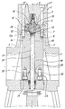
- the high-pressure plunger pump shown in the drawing has a housing 1 and a pump head 2 and is equipped with an inner body 3, which is enclosed by the suction chamber 4 of the pump and is connected to the pump head 2 by screws 5. These screws 5 extend from the outer surface 6 of the pump head over the entire height of the pump head and are screwed with their threaded shaft 7 into threaded bores 8 of the inner body 3.
- valve seat ring 9 is provided, which is positively connected to both the pump head 2 and the inner body 3.
- the valve seat ring 9 is provided with a sleeve-shaped insert 10, which forms the seat for the pressure valve 11.
- the seat surface is provided for an annular suction valve body 12 which has a central overflow bore 13a.
- a spring 14 is assigned to the suction valve body 12.
- Both the suction valve body 12 and the spring 14 are arranged in a stepped bore in the inner body 3.
- suction channels 15 extend to the seat 13 of the suction valve. These suction channels run at an acute angle to the central longitudinal axis 16 of the valve seat ring or the high-pressure plunger pump, in which the pressure valve and the suction valve are arranged coaxially.
- the pump is equipped with a drivable plunger 17, which is slidably mounted in a longitudinal bore 18 of the inner body 3 and in an insertion sleeve 19.
- the insertion sleeve 19 is provided with an annular flange 20 and is received by an extension 21 of the longitudinal bore 18.
- the ring flange 20 of the insertion sleeve 19 is arranged in a recess of the inner body 3 corresponding to the contour of the ring flange.
- a triple step of a recess is provided at the end facing the valve seat ring 9.
- One step is provided for the spring 14, another step for the suction valve body 12 and one step for a projection 26 of the valve seat ring 9.
- valve seat 9 A positive connection between the valve seat 9 and the pump head 2 is achieved by a stepped projection 27 of the valve seat ring 9, which engage in corresponding recesses in the pump head 2.
Landscapes
- Engineering & Computer Science (AREA)
- Mechanical Engineering (AREA)
- General Engineering & Computer Science (AREA)
- Details Of Reciprocating Pumps (AREA)
- Safety Valves (AREA)
Abstract
Description
- Die Erfindung bezieht sich auf eine Hochdruckplungerpumpe, vorzugsweise für Arbeitsdrücke oberhalb 2.000 bar, mit einem Pumpenkopf, einem Gehäuse, einem antreibbaren Plunger, einem koaxial zur Längsachse des Plungers angeordneten Druck- und Saugventil und einem den Arbeitsraum der Pumpe aufweisenden Innenkörper, der von einem die anzusaugende Flüssigkeit enthaltenden Saugraum umschlossen ist.
- Es ist eine Hochdruckplungerpumpe dieser Art bekannt (EP 0 551 590), bei der der den Arbeitsraum der Pumpe aufweisende Innenkörper als schwimmend auf dem Plunger gelagerte Hülse ausgebildet ist. An dem dem Saugventil zugewandten Ende verjüngt sich der Innenraum der Hülse, so daß beim Druckhub die Hülse durch das Fördermedium an einen Einsatzkörper gedrückt wird. Dieser Einsatzkörper ist zweiteilig ausgebildet, wobei das dem Plunger zugewandte Teil die Sitzfläche des Saugventils und das dem Pumpenkopf zugewandte Teil die Sitzfläche des Druckventils aufweist.
- Ausgehend von diesem Stand der Technik liegt der Erfindung die Aufgabe zugrunde, eine Hochdruckplungerpumpe, vorzugsweise für Arbeitsdrücke oberhalb 2.000 bar so zu gestalten, daß sie sich aus wenigen, einfach zu fertigenden Bauteilen zusammensetzt, die eine gute Abdichtung zwischen dem Arbeits- und dem Saugraum gewährleisten.
- Diese Aufgabe wird nach der Erfindung dadurch gelöst, daß der Plunger in einer Längsbohrung des Innenkörpers sowie in einer von einer Erweiterung der Längsbohrung aufgenommenen Einsteckhülse gleitbar gelagert ist, die Einsteckhülse an dem dem Plungerantrieb zugewandten Ende mit einem Ringflansch versehen und im Übergangsbereich vom Ringflansch zum Hülsenkörper eine Dichtung zwischen dem Arbeitsraum und dem Saugraum angeordnet ist.
- Bei der Einsteckhülse wird die Aufweitung durch die Elastizität unter dem Betriebsdruck eliminiert, da bis zur Abdichtung in der Nähe des Ringflansches der Arbeitsdruck von außen und innen herrscht. Da der Dichtspalt in die Berechnung der Leckagerate in der dritten Potenz eingeht, wird bei der erfindungsgemäßen Ausführung die Leckagerate wesentlich verringert.
- Der aus Hartmetall oder Keramik gefertigte Kolben zeigt kaum Verschleißerscheinungen. Von Zeit zu Zeit ist nur die Einsteckhülse auszuwechseln.
- Bei einer vorteilhaften Ausführungsform der erfindungsgemäßen Hochdruckplungerpumpe ist in dem Raum zwischen dem Pumpenkopf und dem den Arbeitsraum enthaltenden Innenkörper ein Ventilsitzring mit Ventilsitzflächen für das Druckventil und für das Saugventil vorgesehen. Ein mit einer mittigen Überströmbohrung ausgerüsteter Saugventilkörper und eine zugeordnete Feder sind in einer an den Ventilsitzring angrenzenden, zylindrischen Ausnehmung des Innenkörpers angeordnet. Der Pumpenkopf ist mit dem Innenkörper verbunden. Diese Verbindung zwischen dem Pumpenkopf und dem Innenkörper wird bei einer vorteilhaften Ausführungsform der Erfindung durch Schrauben vorgenommen, die von der äußeren Begrenzungsfläche des Pumpenkopfes ausgehen und mit ihrem Gewindeschaft in Gewindebohrungen des Innenkörpers der Pumpe eingeschraubt sind.
- Beim Gegenstand der Erfindung ist im Übergangsbereich von dem Gehäuse zum Pumpenkopf als Einsatzkörper nur ein Ventilsitzring vorhanden, der sowohl die Sitzfläche für das Saugventil als auch die Sitzfläche für das Druckventil aufweist.
- Bei der erfindungsgemäßen Hochdruckplungerpumpe für höchste Drücke wird der schädliche Raum besonders gering gehalten, um der Kompressibilität des Mediums möglichst geringe Chancen zu bieten, den Wirkungsgrad zu verschlechtern.
- Weitere Merkmale der Erfindung ergeben sich aus den Unteransprüchen.
- Ein Ausführungsbeispiel der erfindungsgemäßen Hochdruckplungerpumpe ist in der Zeichnung im Längsschnitt dargestellt und wird im folgenden beschrieben.
- Die in der Zeichnung dargestellte Hochdruckplungerpumpe weist ein Gehäuse 1 sowie einen Pumpenkopf 2 auf und ist mit einem Innenkörper 3 ausgerüstet, der von dem Saugraum 4 der Pumpe umschlossen und durch Schrauben 5 mit dem Pumpenkopf 2 verbunden ist. Diese Schrauben 5 erstrecken sich von der Außenfläche 6 des Pumpenkopfes über die gesamte Höhe des Pumpenkopfes und sind mit ihrem Gewindeschaft 7 in Gewindebohrungen 8 des Innenkörpers 3 eingeschraubt.
- Zwischen dem Pumpenkopf 2 und dem Innenkörper 3 ist ein Ventilsitzring 9 vorgesehen, der sowohl mit dem Pumpenkopf 2 als auch mit dem Innenkörper 3 formschlüssig verbunden ist.
- Der Ventilsitzring 9 ist mit einem hülsenförmigen Einsatz 10 versehen, der den Sitz für das Druckventil 11 bildet.
- An der dem Druckventil gegenüberliegenden Seite des Ventilsitzringes 9 ist die Sitzfläche für einen ringförmigen Saugventilkörper 12 vorgesehen, der eine mittige Überströmbohrung 13a aufweist. Dem Saugventilkörper 12 ist eine Feder 14 zugeordnet.
- Sowohl der Saugventilkörper 12 als auch die Feder 14 sind in einer gestuften Bohrung des Innenkörpers 3 angeordnet.
- Durch den Ventilsitzring 9 erstrecken sich Saugkanäle 15 bis zur Sitzfläche 13 des Saugventils. Diese Saugkanäle verlaufen in einem spitzen Winkel zur Mittellängsachse 16 des Ventilsitzringes bzw. der Hochdruckplungerpumpe, in der das Druckventil und das Saugventil koaxial angeordnet sind.
- Die Pumpe ist mit einem antreibbaren Plunger 17 ausgerüstet, der in einer Längsbohrung 18 des Innenkörpers 3 sowie in einer Einsteckhülse 19 gleitbar gelagert ist. Die Einsteckhülse 19 ist mit einem Ringflansch 20 versehen und wird von einer Erweiterung 21 der Längsbohrung 18 aufgenommen. Der Ringflansch 20 der Einsteckhülse 19 ist in einer der Kontur des Ringflansches entsprechenden Aussparung des Innenkörpers 3 angeordnet. In diese Aussparung ragt auch ein Vorsprung 22 eines Deckels 23, der durch Schrauben 24 mit dem Innenkörper 3 verbunden ist. Dieser Vorsprung 22 stützt sich am Ringsflansch 20 ab. Im Übergangsbereich zwischen dem Ringflansch 20 und dem Hülsenkörper der Einsteckhülse 19 ist eine Dichtung 25 angeordnet, die den Arbeitsraum der Pumpe gegenüber dem Saugraum 4 abdichtet. Beim Druckhub des Plungers baut sich in dem Ringspalt zwischen dem Plunger und dem Hülsenkörper der Einsteckhülse 19 und in dem Ringspalt zwischen dem Hülsenkörper und dem Innenkörper 3 ein Druck auf, durch den die elastische Verformung des Hülsenkörpers vollständig oder weitgehend eliminiert wird. Hierdurch ergibt sich eine gute Dichtwirkung der Dichtung 25, die im Übergangsbereich zwischen dem Hülsenkörper und dem Ringflansch 20 angeordnet ist und den Arbeitsraum der Pumpe gegenüber dem Saugraum 4 abdichtet.
- In dem Innenkörper 3 ist an dem dem Ventilsitzring 9 zugewandten Ende eine dreifache Stufung einer Ausnehmung vorgesehen. Die eine Stufung ist für die Feder 14, eine weitere Stufung für den Saugventilkörper 12 und eine Stufung für einen Vorsprung 26 des Ventilsitzringes 9 vorgesehen.
- Durch diesen Vorsprung 26, der in die genannte Ausnehmung des Innenkörpers 3 eingreift, ergibt sich eine formschlüssige Verbindung zwischen dem Ventilsitzring 9 und dem Innenkörper 3.
- Eine formschlüssige Verbindung zwischen dem Ventilsitz 9 und dem Pumpenkopf 2 wird durch einen gestuften Vorsprung 27 des Ventilsitzringes 9 erreicht, der in entsprechende Ausnehmungen des Pumpenkopfes 2 eingreifen.
-
- 1
- Gehäuse
- 2
- Pumpenkopf
- 3
- Innenkörper
- 4
- Saugraum
- 5
- Schraube
- 6
- Außenfläche
- 7
- Gewindeschaft
- 8
- Gewindebohrung
- 9
- Ventilsitzring
- 10
- Einsatz
- 11
- Druckventil
- 12
- Saugventilkörper
- 13
- Sitzfläche
- 13a
- Überströmbohrung
- 14
- Feder
- 15
- Saugkanal
- 16
- Mittellängsachse
- 17
- Plunger
- 18
- Längsbohrung
- 19
- Einsteckhülse
- 20
- Ringflansch
- 21
- Erweiterung
- 22
- Vorsprung
- 23
- Deckel
- 24
- Schraube
- 25
- Dichtung
- 26
- Vorsprung
- 27
- Vorsprung
Claims (9)
- Hochdruckplungerpumpe, vorzugsweise für Arbeitsdrücke oberhalb 2.000 bar, mit einem Pumpenkopf, einem Gehäuse, einem antreibbaren Plunger, einem koaxial zur Längsachse des Plungers angeordneten Druck- und Saugventil und einem den Arbeitsraum der Pumpe aufweisenden Innenkörper, der von einem die anzusaugende Flüssigkeit enthaltenden Saugraum umschlossen ist, dadurch gekennzeichnet, daß der Plunger (17) in einer Längsbohrung (18) des Innenkörpers (3) sowie in einer von einer Erweiterung (21) der Längsbohrung (18) aufgenommenen Einsteckhülse (19) gleitbar gelagert ist, die Einsteckhülse (19) an dem Plungerantrieb zugewandten Ende mit einem Ringflansch (20) versehen und im Übergangsbereich vom Ringflansch zum Hülsenkörper eine Dichtung (25) zwischen dem Arbeitsraum und dem Saugraum (4) angeordnet ist.
- Hochdruckplungerpumpe nach Anspruch 1, dadurch gekennzeichnet, daß der Ringflansch (20) der Einsteckhülse (19) in einer der Kontur des Ringflansches entsprechenden Aussparung des Innenkörpers (3) angeordnet und in die Aussparung ein Vorsprung (22) eines mit dem Innenkörper verschraubten Deckels (23) eingreift und der Vorsprung sich am Ringflansch abstützt.
- Hochdruckplungerpumpe nach Anspruch 1, dadurch gekennzeichnet, daß in dem Raum zwischen dem Pumpenkopf (2) und dem den Arbeitsraum enthaltenden Innenkörper (3) ein Ventilsitzring (9) mit Ventilsitzflächen für das Druckventil (11) und für das Saugventil vorgesehen, ein mit einer mittigen Überströmbohrung ausgerüsteter Saugventilkörper (12) und eine zugeordnete Feder (14) in einer an den Ventilsitzring angrenzenden, zylindrischen Ausnehmung des Innenkörpers angeordnet und der Pumpenkopf (2) mit dem Innenkörper (3) verbunden ist.
- Hochdruckplungerpumpe nach Anspruch 3, dadurch gekennzeichnet, daß die Ausnehmung in dem Innenkörper (3) gestuft ausgeführt ist.
- Hochdruckplungerpumpe nach Anspruch 4, dadurch gekennzeichnet, daß eine Stufung für die Feder (14), eine weitere Stufung für den Saugventilkörper (12) und eine Stufung für einen Vorsprung (26) des Ventilsitzringes (9) zur formschlüssigen Verbindung des Ventilsitzringes mit dem Innenkörper (3) vorgesehen sind.
- Hochdruckplungerpumpe nach Anspruch 3, dadurch gekennzeichnet, daß die Sitzfläche des Ventilkörpers des Druckventils durch einen in dem Ventilsitzring (9) angeordneten, hülsenförmigen Einsatz (10) gebildet ist.
- Hochdruckplungerpumpe nach Anspruch 6, dadurch gekennzeichnet, daß der Durchflußquerschnitt des hülsenförmigen Einsatzes (10) sich in Richtung auf den Ventilkörper des Druckventils erweitert.
- Hochdruckplungerpumpe nach Anspruch 3, dadurch gekennzeichnet, daß der Pumpenkopf (2) mit dem Innenkörper (3) verschraubt ist.
- Hochdruckplungerpumpe nach Anspruch 8, dadurch gekennzeichnet, daß der Pumpenkopf (2) mit dem Ventilsitzring (9) und der Ventilsitzring (9) mit dem Innenkörper (3) formschlüssig verbunden sind.
Applications Claiming Priority (2)
| Application Number | Priority Date | Filing Date | Title |
|---|---|---|---|
| DE19604132A DE19604132C2 (de) | 1996-02-06 | 1996-02-06 | Hochdruckplungerpumpe, vorzugsweise für Arbeitsdrücke oberhalb 2.000 bar |
| DE19604132 | 1996-02-06 |
Publications (3)
| Publication Number | Publication Date |
|---|---|
| EP0789147A2 true EP0789147A2 (de) | 1997-08-13 |
| EP0789147A3 EP0789147A3 (de) | 1998-09-02 |
| EP0789147B1 EP0789147B1 (de) | 2001-10-31 |
Family
ID=7784564
Family Applications (1)
| Application Number | Title | Priority Date | Filing Date |
|---|---|---|---|
| EP97100707A Expired - Lifetime EP0789147B1 (de) | 1996-02-06 | 1997-01-17 | Hochdruckplungerpumpe, vorzugsweise für Arbeitsdrücke oberhalb 2.000 bar |
Country Status (7)
| Country | Link |
|---|---|
| US (1) | US5848880A (de) |
| EP (1) | EP0789147B1 (de) |
| JP (1) | JP3954143B2 (de) |
| AU (1) | AU705265B2 (de) |
| DE (2) | DE19604132C2 (de) |
| DK (1) | DK0789147T3 (de) |
| ES (1) | ES2166476T3 (de) |
Families Citing this family (33)
| Publication number | Priority date | Publication date | Assignee | Title |
|---|---|---|---|---|
| EP0892174B1 (de) | 1997-07-17 | 2001-10-31 | Jürgen Weigel | Pumpenkopf für eine Hubkolbenpumpe |
| DE29716906U1 (de) * | 1997-07-17 | 1997-11-20 | Eberherr, Herbert, 97638 Mellrichstadt | Pumpenkopf für eine Hub-Kolbenpumpe |
| US5980224A (en) * | 1997-12-18 | 1999-11-09 | Chrysler Corporation | Fuel injection pump |
| DE20008015U1 (de) | 2000-05-05 | 2000-08-31 | Neuman & Esser Maschinenfabrik GmbH & Co. KG, 52531 Übach-Palenberg | Geschrumpfter Zylinder für Hochdruck-Kolbenkompressoren |
| CN100453804C (zh) * | 2007-09-05 | 2009-01-21 | 吴赛珍 | 缸体大圆端面对内花键垂直的加工方法 |
| US8986253B2 (en) | 2008-01-25 | 2015-03-24 | Tandem Diabetes Care, Inc. | Two chamber pumps and related methods |
| DE202008001458U1 (de) * | 2008-02-01 | 2008-03-27 | Hammelmann Maschinenfabrik Gmbh | Hochdruckventilanordnung |
| US8408421B2 (en) | 2008-09-16 | 2013-04-02 | Tandem Diabetes Care, Inc. | Flow regulating stopcocks and related methods |
| CA2737461A1 (en) | 2008-09-19 | 2010-03-25 | Tandem Diabetes Care, Inc. | Solute concentration measurement device and related methods |
| EP2724739B1 (de) | 2009-07-30 | 2015-07-01 | Tandem Diabetes Care, Inc. | Tragbares Infusionspumpensystem |
| US9180242B2 (en) | 2012-05-17 | 2015-11-10 | Tandem Diabetes Care, Inc. | Methods and devices for multiple fluid transfer |
| US8904912B2 (en) | 2012-08-16 | 2014-12-09 | Omax Corporation | Control valves for waterjet systems and related devices, systems, and methods |
| US9095955B2 (en) | 2012-08-16 | 2015-08-04 | Omax Corporation | Control valves for waterjet systems and related devices, systems and methods |
| US9173998B2 (en) | 2013-03-14 | 2015-11-03 | Tandem Diabetes Care, Inc. | System and method for detecting occlusions in an infusion pump |
| US9771445B2 (en) | 2014-03-31 | 2017-09-26 | Sabic Global Technologies B.V. | Process for the preparation of an ethylene copolymer in a tubular reactor |
| US11554461B1 (en) | 2018-02-13 | 2023-01-17 | Omax Corporation | Articulating apparatus of a waterjet system and related technology |
| US11578710B2 (en) | 2019-05-02 | 2023-02-14 | Kerr Machine Co. | Fracturing pump with in-line fluid end |
| US11578711B2 (en) | 2019-11-18 | 2023-02-14 | Kerr Machine Co. | Fluid routing plug |
| US11346339B2 (en) | 2019-11-18 | 2022-05-31 | Kerr Machine Co. | High pressure pump |
| US12188458B2 (en) | 2019-11-18 | 2025-01-07 | Kerr Machine Co. | Fluid end assembly |
| US11686296B2 (en) | 2019-11-18 | 2023-06-27 | Kerr Machine Co. | Fluid routing plug |
| US12292040B2 (en) | 2019-11-18 | 2025-05-06 | Kerr Machine Co. | High pressure pump |
| US12264661B2 (en) | 2019-11-18 | 2025-04-01 | Kerr Machine Co. | High pressure pump |
| US11644018B2 (en) | 2019-11-18 | 2023-05-09 | Kerr Machine Co. | Fluid end |
| US11635068B2 (en) | 2019-11-18 | 2023-04-25 | Kerr Machine Co. | Modular power end |
| US12051316B2 (en) | 2019-12-18 | 2024-07-30 | Hypertherm, Inc. | Liquid jet cutting head sensor systems and methods |
| EP4127527A1 (de) | 2020-03-24 | 2023-02-08 | Hypertherm, Inc. | Hochdruckdichtung für ein flüssigkeitsstrahlschneidsystem |
| KR20230005840A (ko) | 2020-03-30 | 2023-01-10 | 하이퍼썸, 인크. | 다기능 접속 종방향 단부들을 갖는 액체 제트 펌프를 위한 실린더 |
| US11920583B2 (en) | 2021-03-05 | 2024-03-05 | Kerr Machine Co. | Fluid end with clamped retention |
| DE102021112742A1 (de) | 2021-05-17 | 2022-11-17 | Hammelmann GmbH | Dichtungseinrichtung für eine Stange |
| US11946465B2 (en) | 2021-08-14 | 2024-04-02 | Kerr Machine Co. | Packing seal assembly |
| US11808364B2 (en) | 2021-11-11 | 2023-11-07 | Kerr Machine Co. | Valve body |
| US12297827B2 (en) | 2023-06-05 | 2025-05-13 | Kerr Machine Co. | Fluid end with clamped retention |
Citations (1)
| Publication number | Priority date | Publication date | Assignee | Title |
|---|---|---|---|---|
| EP0551590A1 (de) | 1992-01-11 | 1993-07-21 | Paul Hammelmann | Hochdruckplungerpumpe, vorzugsweise für Arbeitsdrücke oberhalb 2000 bar |
Family Cites Families (17)
| Publication number | Priority date | Publication date | Assignee | Title |
|---|---|---|---|---|
| US2656820A (en) * | 1948-03-16 | 1953-10-27 | Philip S Becker | Power-operated vise |
| US3260217A (en) * | 1964-08-05 | 1966-07-12 | Frank Wheatley Pump & Valve Ma | Pump having radial discharge valve |
| US3298319A (en) * | 1964-10-26 | 1967-01-17 | Donald W Barlow | Pumping system for slurry and other solutions |
| US3811801A (en) * | 1972-05-30 | 1974-05-21 | Ingersoll Rand Co | Multi-plunger reciprocating pump |
| US3891356A (en) * | 1973-11-21 | 1975-06-24 | Armco Steel Corp | Fluid guide plunger system |
| DE3404520C2 (de) * | 1984-02-09 | 1997-01-09 | Uraca Pumpen | Pumpe oder Hydraulikanlage |
| DE8717850U1 (de) * | 1987-03-24 | 1990-08-09 | Hammelmann, Paul, 4740 Oelde | Hochdruckplungerpumpe |
| EP0343773B1 (de) * | 1988-03-23 | 1993-11-18 | Kabushiki Kaisha Little Rock | Flüssigkeitspumpe und Ventilvorrichtung |
| US4878815A (en) * | 1988-05-18 | 1989-11-07 | Stachowiak J Edward | High pressure reciprocating pump apparatus |
| US5050895A (en) * | 1989-04-04 | 1991-09-24 | Flow International Corporation | High pressure dynamic seal |
| US5064354A (en) * | 1990-06-04 | 1991-11-12 | Robertson Walter W | High pressure fluid pump |
| DE4038613C3 (de) * | 1990-12-04 | 1998-09-17 | Woma Maasberg Co Gmbh W | Mehrzylindrige Hochdruckplungerpumpe |
| US5230363A (en) * | 1991-04-10 | 1993-07-27 | Dowell Schlumberger Incorporated | Suction valve for high pressure slurry pump |
| US5273405A (en) * | 1992-07-07 | 1993-12-28 | Jet Edge, Inc. | Fluid cushioning apparatus for hydraulic intensifier assembly |
| DE4240590A1 (de) * | 1992-12-03 | 1994-06-09 | Uraca Pumpen | Verdrängerpumpe |
| WO1994020754A1 (en) * | 1993-03-12 | 1994-09-15 | Saurwein Albert C | Fluid pressure intensifying apparatus |
| US5493954A (en) * | 1994-11-18 | 1996-02-27 | Flow International Corporation | Self-venting seal assembly |
-
1996
- 1996-02-06 DE DE19604132A patent/DE19604132C2/de not_active Expired - Fee Related
-
1997
- 1997-01-17 DE DE59705122T patent/DE59705122D1/de not_active Expired - Lifetime
- 1997-01-17 EP EP97100707A patent/EP0789147B1/de not_active Expired - Lifetime
- 1997-01-17 DK DK97100707T patent/DK0789147T3/da active
- 1997-01-17 ES ES97100707T patent/ES2166476T3/es not_active Expired - Lifetime
- 1997-01-29 US US08/790,390 patent/US5848880A/en not_active Expired - Lifetime
- 1997-01-30 AU AU12400/97A patent/AU705265B2/en not_active Ceased
- 1997-02-05 JP JP02262797A patent/JP3954143B2/ja not_active Expired - Fee Related
Patent Citations (1)
| Publication number | Priority date | Publication date | Assignee | Title |
|---|---|---|---|---|
| EP0551590A1 (de) | 1992-01-11 | 1993-07-21 | Paul Hammelmann | Hochdruckplungerpumpe, vorzugsweise für Arbeitsdrücke oberhalb 2000 bar |
Also Published As
| Publication number | Publication date |
|---|---|
| JP3954143B2 (ja) | 2007-08-08 |
| AU705265B2 (en) | 1999-05-20 |
| JPH09228965A (ja) | 1997-09-02 |
| US5848880A (en) | 1998-12-15 |
| DE19604132A1 (de) | 1997-08-07 |
| AU1240097A (en) | 1997-08-14 |
| ES2166476T3 (es) | 2002-04-16 |
| DE59705122D1 (de) | 2001-12-06 |
| EP0789147A3 (de) | 1998-09-02 |
| DK0789147T3 (da) | 2002-02-18 |
| EP0789147B1 (de) | 2001-10-31 |
| DE19604132C2 (de) | 2000-04-13 |
Similar Documents
| Publication | Publication Date | Title |
|---|---|---|
| EP0789147B1 (de) | Hochdruckplungerpumpe, vorzugsweise für Arbeitsdrücke oberhalb 2.000 bar | |
| DE69512979T2 (de) | Flüssigkeitspumpe | |
| EP0256221A1 (de) | Anordnung zur Abdichtung einer Stange | |
| DE4239362A1 (de) | Ventil, insbesondere Druckventil für eine Radialkolbenpumpe, mit wenigen Komponenten | |
| DE2323455A1 (de) | Dichtring fuer kolbenringe | |
| DE2615530A1 (de) | Hochdruckplungerpumpe | |
| DE2834895C2 (de) | Hydraulische Formschließvorrichtung mit einem Druckübersetzer | |
| DE3232083A1 (de) | Radialkolbenpumpe | |
| DE102012224317A1 (de) | Steckpumpe | |
| EP0551590B1 (de) | Hochdruckplungerpumpe, vorzugsweise für Arbeitsdrücke oberhalb 2000 bar | |
| EP0707166A1 (de) | Dichtung | |
| DE2317357C3 (de) | ||
| DE2829351A1 (de) | Leckgas-rueckfuehrvorrichtung fuer eine stirling-maschine | |
| DE3420890C2 (de) | ||
| EP0925453B1 (de) | Flügelzellenpumpe | |
| DE719353C (de) | Wellenspaltdichtung fuer stopfbuechslose Kreiselpumpen | |
| EP1604112B1 (de) | Radialkolbenpumpe | |
| WO2004025123A1 (de) | Pumpe für ein hochdruckreinigungsgerät | |
| DE29623354U1 (de) | Hochdruckplungerpumpe, vorzugsweise für Arbeitsdrücke oberhalb 2.000 bar | |
| DE102019128682A1 (de) | Fördervorrichtung zumindest zu einem Fördern eines Fluids und Pumpe mit einer derartigen Fördervorrichtung | |
| DE202608C (de) | ||
| DE2640440A1 (de) | Dosier-kolbenpumpe | |
| DE3337839C2 (de) | Pumpenaggregat | |
| DE102017112110A1 (de) | Plungerpumpe sowie Verwendung einer Plungerpumpe | |
| DE102005017283B3 (de) | Kolbenpumpe für eine Fahrzeugbremsanlage |
Legal Events
| Date | Code | Title | Description |
|---|---|---|---|
| PUAI | Public reference made under article 153(3) epc to a published international application that has entered the european phase |
Free format text: ORIGINAL CODE: 0009012 |
|
| AK | Designated contracting states |
Kind code of ref document: A2 Designated state(s): CH DE DK ES FR GB IT LI NL SE |
|
| PUAL | Search report despatched |
Free format text: ORIGINAL CODE: 0009013 |
|
| AK | Designated contracting states |
Kind code of ref document: A3 Designated state(s): CH DE DK ES FR GB IT LI NL SE |
|
| 17P | Request for examination filed |
Effective date: 19980818 |
|
| 17Q | First examination report despatched |
Effective date: 20000719 |
|
| GRAG | Despatch of communication of intention to grant |
Free format text: ORIGINAL CODE: EPIDOS AGRA |
|
| GRAG | Despatch of communication of intention to grant |
Free format text: ORIGINAL CODE: EPIDOS AGRA |
|
| GRAH | Despatch of communication of intention to grant a patent |
Free format text: ORIGINAL CODE: EPIDOS IGRA |
|
| GRAH | Despatch of communication of intention to grant a patent |
Free format text: ORIGINAL CODE: EPIDOS IGRA |
|
| RAP3 | Party data changed (applicant data changed or rights of an application transferred) |
Owner name: HAMMELMANN MASCHINENFABRIK GMBH |
|
| GRAA | (expected) grant |
Free format text: ORIGINAL CODE: 0009210 |
|
| AK | Designated contracting states |
Kind code of ref document: B1 Designated state(s): CH DE DK ES FR GB IT LI NL SE |
|
| REG | Reference to a national code |
Ref country code: CH Ref legal event code: EP |
|
| REG | Reference to a national code |
Ref country code: CH Ref legal event code: NV Representative=s name: ISLER & PEDRAZZINI AG |
|
| GBT | Gb: translation of ep patent filed (gb section 77(6)(a)/1977) |
Effective date: 20011031 |
|
| REF | Corresponds to: |
Ref document number: 59705122 Country of ref document: DE Date of ref document: 20011206 |
|
| REG | Reference to a national code |
Ref country code: GB Ref legal event code: IF02 |
|
| REG | Reference to a national code |
Ref country code: DK Ref legal event code: T3 |
|
| ET | Fr: translation filed | ||
| REG | Reference to a national code |
Ref country code: ES Ref legal event code: FG2A Ref document number: 2166476 Country of ref document: ES Kind code of ref document: T3 |
|
| PLBE | No opposition filed within time limit |
Free format text: ORIGINAL CODE: 0009261 |
|
| STAA | Information on the status of an ep patent application or granted ep patent |
Free format text: STATUS: NO OPPOSITION FILED WITHIN TIME LIMIT |
|
| 26N | No opposition filed | ||
| REG | Reference to a national code |
Ref country code: CH Ref legal event code: PCAR Free format text: ISLER & PEDRAZZINI AG;POSTFACH 1772;8027 ZUERICH (CH) |
|
| PGFP | Annual fee paid to national office [announced via postgrant information from national office to epo] |
Ref country code: DK Payment date: 20110125 Year of fee payment: 15 |
|
| PGFP | Annual fee paid to national office [announced via postgrant information from national office to epo] |
Ref country code: NL Payment date: 20110119 Year of fee payment: 15 Ref country code: IT Payment date: 20110126 Year of fee payment: 15 Ref country code: FR Payment date: 20110201 Year of fee payment: 15 Ref country code: SE Payment date: 20110121 Year of fee payment: 15 Ref country code: DE Payment date: 20110113 Year of fee payment: 15 Ref country code: CH Payment date: 20110125 Year of fee payment: 15 |
|
| PGFP | Annual fee paid to national office [announced via postgrant information from national office to epo] |
Ref country code: ES Payment date: 20110121 Year of fee payment: 15 Ref country code: GB Payment date: 20110121 Year of fee payment: 15 |
|
| REG | Reference to a national code |
Ref country code: NL Ref legal event code: V1 Effective date: 20120801 |
|
| REG | Reference to a national code |
Ref country code: CH Ref legal event code: PL |
|
| REG | Reference to a national code |
Ref country code: SE Ref legal event code: EUG |
|
| REG | Reference to a national code |
Ref country code: DK Ref legal event code: EBP |
|
| GBPC | Gb: european patent ceased through non-payment of renewal fee |
Effective date: 20120117 |
|
| REG | Reference to a national code |
Ref country code: FR Ref legal event code: ST Effective date: 20120928 |
|
| PG25 | Lapsed in a contracting state [announced via postgrant information from national office to epo] |
Ref country code: CH Free format text: LAPSE BECAUSE OF NON-PAYMENT OF DUE FEES Effective date: 20120131 Ref country code: LI Free format text: LAPSE BECAUSE OF NON-PAYMENT OF DUE FEES Effective date: 20120131 Ref country code: SE Free format text: LAPSE BECAUSE OF NON-PAYMENT OF DUE FEES Effective date: 20120118 Ref country code: GB Free format text: LAPSE BECAUSE OF NON-PAYMENT OF DUE FEES Effective date: 20120117 Ref country code: DE Free format text: LAPSE BECAUSE OF NON-PAYMENT OF DUE FEES Effective date: 20120801 |
|
| REG | Reference to a national code |
Ref country code: DE Ref legal event code: R119 Ref document number: 59705122 Country of ref document: DE Effective date: 20120801 |
|
| PG25 | Lapsed in a contracting state [announced via postgrant information from national office to epo] |
Ref country code: IT Free format text: LAPSE BECAUSE OF NON-PAYMENT OF DUE FEES Effective date: 20120117 |
|
| PG25 | Lapsed in a contracting state [announced via postgrant information from national office to epo] |
Ref country code: FR Free format text: LAPSE BECAUSE OF NON-PAYMENT OF DUE FEES Effective date: 20120131 |
|
| PG25 | Lapsed in a contracting state [announced via postgrant information from national office to epo] |
Ref country code: DK Free format text: LAPSE BECAUSE OF NON-PAYMENT OF DUE FEES Effective date: 20120131 Ref country code: NL Free format text: LAPSE BECAUSE OF NON-PAYMENT OF DUE FEES Effective date: 20120801 |
|
| REG | Reference to a national code |
Ref country code: ES Ref legal event code: FD2A Effective date: 20130705 |
|
| PG25 | Lapsed in a contracting state [announced via postgrant information from national office to epo] |
Ref country code: ES Free format text: LAPSE BECAUSE OF NON-PAYMENT OF DUE FEES Effective date: 20120118 |