EP0788211A2 - Verbindungssystem mit zugehörigem Verfahren - Google Patents
Verbindungssystem mit zugehörigem Verfahren Download PDFInfo
- Publication number
- EP0788211A2 EP0788211A2 EP97101385A EP97101385A EP0788211A2 EP 0788211 A2 EP0788211 A2 EP 0788211A2 EP 97101385 A EP97101385 A EP 97101385A EP 97101385 A EP97101385 A EP 97101385A EP 0788211 A2 EP0788211 A2 EP 0788211A2
- Authority
- EP
- European Patent Office
- Prior art keywords
- coil unit
- vehicle
- primary coil
- secondary coil
- primary
- Prior art date
- Legal status (The legal status is an assumption and is not a legal conclusion. Google has not performed a legal analysis and makes no representation as to the accuracy of the status listed.)
- Granted
Links
Images


Classifications
-
- H—ELECTRICITY
- H02—GENERATION; CONVERSION OR DISTRIBUTION OF ELECTRIC POWER
- H02J—CIRCUIT ARRANGEMENTS OR SYSTEMS FOR SUPPLYING OR DISTRIBUTING ELECTRIC POWER; SYSTEMS FOR STORING ELECTRIC ENERGY
- H02J7/00—Circuit arrangements for charging or depolarising batteries or for supplying loads from batteries
- H02J7/0042—Circuit arrangements for charging or depolarising batteries or for supplying loads from batteries characterised by the mechanical construction
- H02J7/0045—Circuit arrangements for charging or depolarising batteries or for supplying loads from batteries characterised by the mechanical construction concerning the insertion or the connection of the batteries
-
- B—PERFORMING OPERATIONS; TRANSPORTING
- B60—VEHICLES IN GENERAL
- B60L—PROPULSION OF ELECTRICALLY-PROPELLED VEHICLES; SUPPLYING ELECTRIC POWER FOR AUXILIARY EQUIPMENT OF ELECTRICALLY-PROPELLED VEHICLES; ELECTRODYNAMIC BRAKE SYSTEMS FOR VEHICLES IN GENERAL; MAGNETIC SUSPENSION OR LEVITATION FOR VEHICLES; MONITORING OPERATING VARIABLES OF ELECTRICALLY-PROPELLED VEHICLES; ELECTRIC SAFETY DEVICES FOR ELECTRICALLY-PROPELLED VEHICLES
- B60L50/00—Electric propulsion with power supplied within the vehicle
- B60L50/50—Electric propulsion with power supplied within the vehicle using propulsion power supplied by batteries or fuel cells
- B60L50/52—Electric propulsion with power supplied within the vehicle using propulsion power supplied by batteries or fuel cells characterised by DC-motors
-
- B—PERFORMING OPERATIONS; TRANSPORTING
- B60—VEHICLES IN GENERAL
- B60L—PROPULSION OF ELECTRICALLY-PROPELLED VEHICLES; SUPPLYING ELECTRIC POWER FOR AUXILIARY EQUIPMENT OF ELECTRICALLY-PROPELLED VEHICLES; ELECTRODYNAMIC BRAKE SYSTEMS FOR VEHICLES IN GENERAL; MAGNETIC SUSPENSION OR LEVITATION FOR VEHICLES; MONITORING OPERATING VARIABLES OF ELECTRICALLY-PROPELLED VEHICLES; ELECTRIC SAFETY DEVICES FOR ELECTRICALLY-PROPELLED VEHICLES
- B60L53/00—Methods of charging batteries, specially adapted for electric vehicles; Charging stations or on-board charging equipment therefor; Exchange of energy storage elements in electric vehicles
- B60L53/10—Methods of charging batteries, specially adapted for electric vehicles; Charging stations or on-board charging equipment therefor; Exchange of energy storage elements in electric vehicles characterised by the energy transfer between the charging station and the vehicle
- B60L53/12—Inductive energy transfer
- B60L53/126—Methods for pairing a vehicle and a charging station, e.g. establishing a one-to-one relation between a wireless power transmitter and a wireless power receiver
-
- B—PERFORMING OPERATIONS; TRANSPORTING
- B60—VEHICLES IN GENERAL
- B60L—PROPULSION OF ELECTRICALLY-PROPELLED VEHICLES; SUPPLYING ELECTRIC POWER FOR AUXILIARY EQUIPMENT OF ELECTRICALLY-PROPELLED VEHICLES; ELECTRODYNAMIC BRAKE SYSTEMS FOR VEHICLES IN GENERAL; MAGNETIC SUSPENSION OR LEVITATION FOR VEHICLES; MONITORING OPERATING VARIABLES OF ELECTRICALLY-PROPELLED VEHICLES; ELECTRIC SAFETY DEVICES FOR ELECTRICALLY-PROPELLED VEHICLES
- B60L53/00—Methods of charging batteries, specially adapted for electric vehicles; Charging stations or on-board charging equipment therefor; Exchange of energy storage elements in electric vehicles
- B60L53/10—Methods of charging batteries, specially adapted for electric vehicles; Charging stations or on-board charging equipment therefor; Exchange of energy storage elements in electric vehicles characterised by the energy transfer between the charging station and the vehicle
- B60L53/14—Conductive energy transfer
-
- B—PERFORMING OPERATIONS; TRANSPORTING
- B60—VEHICLES IN GENERAL
- B60L—PROPULSION OF ELECTRICALLY-PROPELLED VEHICLES; SUPPLYING ELECTRIC POWER FOR AUXILIARY EQUIPMENT OF ELECTRICALLY-PROPELLED VEHICLES; ELECTRODYNAMIC BRAKE SYSTEMS FOR VEHICLES IN GENERAL; MAGNETIC SUSPENSION OR LEVITATION FOR VEHICLES; MONITORING OPERATING VARIABLES OF ELECTRICALLY-PROPELLED VEHICLES; ELECTRIC SAFETY DEVICES FOR ELECTRICALLY-PROPELLED VEHICLES
- B60L53/00—Methods of charging batteries, specially adapted for electric vehicles; Charging stations or on-board charging equipment therefor; Exchange of energy storage elements in electric vehicles
- B60L53/30—Constructional details of charging stations
- B60L53/305—Communication interfaces
-
- B—PERFORMING OPERATIONS; TRANSPORTING
- B60—VEHICLES IN GENERAL
- B60L—PROPULSION OF ELECTRICALLY-PROPELLED VEHICLES; SUPPLYING ELECTRIC POWER FOR AUXILIARY EQUIPMENT OF ELECTRICALLY-PROPELLED VEHICLES; ELECTRODYNAMIC BRAKE SYSTEMS FOR VEHICLES IN GENERAL; MAGNETIC SUSPENSION OR LEVITATION FOR VEHICLES; MONITORING OPERATING VARIABLES OF ELECTRICALLY-PROPELLED VEHICLES; ELECTRIC SAFETY DEVICES FOR ELECTRICALLY-PROPELLED VEHICLES
- B60L53/00—Methods of charging batteries, specially adapted for electric vehicles; Charging stations or on-board charging equipment therefor; Exchange of energy storage elements in electric vehicles
- B60L53/30—Constructional details of charging stations
- B60L53/35—Means for automatic or assisted adjustment of the relative position of charging devices and vehicles
- B60L53/36—Means for automatic or assisted adjustment of the relative position of charging devices and vehicles by positioning the vehicle
-
- B—PERFORMING OPERATIONS; TRANSPORTING
- B60—VEHICLES IN GENERAL
- B60L—PROPULSION OF ELECTRICALLY-PROPELLED VEHICLES; SUPPLYING ELECTRIC POWER FOR AUXILIARY EQUIPMENT OF ELECTRICALLY-PROPELLED VEHICLES; ELECTRODYNAMIC BRAKE SYSTEMS FOR VEHICLES IN GENERAL; MAGNETIC SUSPENSION OR LEVITATION FOR VEHICLES; MONITORING OPERATING VARIABLES OF ELECTRICALLY-PROPELLED VEHICLES; ELECTRIC SAFETY DEVICES FOR ELECTRICALLY-PROPELLED VEHICLES
- B60L53/00—Methods of charging batteries, specially adapted for electric vehicles; Charging stations or on-board charging equipment therefor; Exchange of energy storage elements in electric vehicles
- B60L53/30—Constructional details of charging stations
- B60L53/35—Means for automatic or assisted adjustment of the relative position of charging devices and vehicles
- B60L53/38—Means for automatic or assisted adjustment of the relative position of charging devices and vehicles specially adapted for charging by inductive energy transfer
-
- B—PERFORMING OPERATIONS; TRANSPORTING
- B60—VEHICLES IN GENERAL
- B60L—PROPULSION OF ELECTRICALLY-PROPELLED VEHICLES; SUPPLYING ELECTRIC POWER FOR AUXILIARY EQUIPMENT OF ELECTRICALLY-PROPELLED VEHICLES; ELECTRODYNAMIC BRAKE SYSTEMS FOR VEHICLES IN GENERAL; MAGNETIC SUSPENSION OR LEVITATION FOR VEHICLES; MONITORING OPERATING VARIABLES OF ELECTRICALLY-PROPELLED VEHICLES; ELECTRIC SAFETY DEVICES FOR ELECTRICALLY-PROPELLED VEHICLES
- B60L53/00—Methods of charging batteries, specially adapted for electric vehicles; Charging stations or on-board charging equipment therefor; Exchange of energy storage elements in electric vehicles
- B60L53/60—Monitoring or controlling charging stations
- B60L53/65—Monitoring or controlling charging stations involving identification of vehicles or their battery types
-
- B—PERFORMING OPERATIONS; TRANSPORTING
- B60—VEHICLES IN GENERAL
- B60L—PROPULSION OF ELECTRICALLY-PROPELLED VEHICLES; SUPPLYING ELECTRIC POWER FOR AUXILIARY EQUIPMENT OF ELECTRICALLY-PROPELLED VEHICLES; ELECTRODYNAMIC BRAKE SYSTEMS FOR VEHICLES IN GENERAL; MAGNETIC SUSPENSION OR LEVITATION FOR VEHICLES; MONITORING OPERATING VARIABLES OF ELECTRICALLY-PROPELLED VEHICLES; ELECTRIC SAFETY DEVICES FOR ELECTRICALLY-PROPELLED VEHICLES
- B60L53/00—Methods of charging batteries, specially adapted for electric vehicles; Charging stations or on-board charging equipment therefor; Exchange of energy storage elements in electric vehicles
- B60L53/60—Monitoring or controlling charging stations
- B60L53/66—Data transfer between charging stations and vehicles
- B60L53/665—Methods related to measuring, billing or payment
-
- H—ELECTRICITY
- H02—GENERATION; CONVERSION OR DISTRIBUTION OF ELECTRIC POWER
- H02J—CIRCUIT ARRANGEMENTS OR SYSTEMS FOR SUPPLYING OR DISTRIBUTING ELECTRIC POWER; SYSTEMS FOR STORING ELECTRIC ENERGY
- H02J50/00—Circuit arrangements or systems for wireless supply or distribution of electric power
- H02J50/10—Circuit arrangements or systems for wireless supply or distribution of electric power using inductive coupling
-
- H—ELECTRICITY
- H02—GENERATION; CONVERSION OR DISTRIBUTION OF ELECTRIC POWER
- H02J—CIRCUIT ARRANGEMENTS OR SYSTEMS FOR SUPPLYING OR DISTRIBUTING ELECTRIC POWER; SYSTEMS FOR STORING ELECTRIC ENERGY
- H02J50/00—Circuit arrangements or systems for wireless supply or distribution of electric power
- H02J50/90—Circuit arrangements or systems for wireless supply or distribution of electric power involving detection or optimisation of position, e.g. alignment
-
- Y—GENERAL TAGGING OF NEW TECHNOLOGICAL DEVELOPMENTS; GENERAL TAGGING OF CROSS-SECTIONAL TECHNOLOGIES SPANNING OVER SEVERAL SECTIONS OF THE IPC; TECHNICAL SUBJECTS COVERED BY FORMER USPC CROSS-REFERENCE ART COLLECTIONS [XRACs] AND DIGESTS
- Y02—TECHNOLOGIES OR APPLICATIONS FOR MITIGATION OR ADAPTATION AGAINST CLIMATE CHANGE
- Y02T—CLIMATE CHANGE MITIGATION TECHNOLOGIES RELATED TO TRANSPORTATION
- Y02T10/00—Road transport of goods or passengers
- Y02T10/60—Other road transportation technologies with climate change mitigation effect
- Y02T10/70—Energy storage systems for electromobility, e.g. batteries
-
- Y—GENERAL TAGGING OF NEW TECHNOLOGICAL DEVELOPMENTS; GENERAL TAGGING OF CROSS-SECTIONAL TECHNOLOGIES SPANNING OVER SEVERAL SECTIONS OF THE IPC; TECHNICAL SUBJECTS COVERED BY FORMER USPC CROSS-REFERENCE ART COLLECTIONS [XRACs] AND DIGESTS
- Y02—TECHNOLOGIES OR APPLICATIONS FOR MITIGATION OR ADAPTATION AGAINST CLIMATE CHANGE
- Y02T—CLIMATE CHANGE MITIGATION TECHNOLOGIES RELATED TO TRANSPORTATION
- Y02T10/00—Road transport of goods or passengers
- Y02T10/60—Other road transportation technologies with climate change mitigation effect
- Y02T10/7072—Electromobility specific charging systems or methods for batteries, ultracapacitors, supercapacitors or double-layer capacitors
-
- Y—GENERAL TAGGING OF NEW TECHNOLOGICAL DEVELOPMENTS; GENERAL TAGGING OF CROSS-SECTIONAL TECHNOLOGIES SPANNING OVER SEVERAL SECTIONS OF THE IPC; TECHNICAL SUBJECTS COVERED BY FORMER USPC CROSS-REFERENCE ART COLLECTIONS [XRACs] AND DIGESTS
- Y02—TECHNOLOGIES OR APPLICATIONS FOR MITIGATION OR ADAPTATION AGAINST CLIMATE CHANGE
- Y02T—CLIMATE CHANGE MITIGATION TECHNOLOGIES RELATED TO TRANSPORTATION
- Y02T90/00—Enabling technologies or technologies with a potential or indirect contribution to GHG emissions mitigation
- Y02T90/10—Technologies relating to charging of electric vehicles
- Y02T90/12—Electric charging stations
-
- Y—GENERAL TAGGING OF NEW TECHNOLOGICAL DEVELOPMENTS; GENERAL TAGGING OF CROSS-SECTIONAL TECHNOLOGIES SPANNING OVER SEVERAL SECTIONS OF THE IPC; TECHNICAL SUBJECTS COVERED BY FORMER USPC CROSS-REFERENCE ART COLLECTIONS [XRACs] AND DIGESTS
- Y02—TECHNOLOGIES OR APPLICATIONS FOR MITIGATION OR ADAPTATION AGAINST CLIMATE CHANGE
- Y02T—CLIMATE CHANGE MITIGATION TECHNOLOGIES RELATED TO TRANSPORTATION
- Y02T90/00—Enabling technologies or technologies with a potential or indirect contribution to GHG emissions mitigation
- Y02T90/10—Technologies relating to charging of electric vehicles
- Y02T90/14—Plug-in electric vehicles
-
- Y—GENERAL TAGGING OF NEW TECHNOLOGICAL DEVELOPMENTS; GENERAL TAGGING OF CROSS-SECTIONAL TECHNOLOGIES SPANNING OVER SEVERAL SECTIONS OF THE IPC; TECHNICAL SUBJECTS COVERED BY FORMER USPC CROSS-REFERENCE ART COLLECTIONS [XRACs] AND DIGESTS
- Y02—TECHNOLOGIES OR APPLICATIONS FOR MITIGATION OR ADAPTATION AGAINST CLIMATE CHANGE
- Y02T—CLIMATE CHANGE MITIGATION TECHNOLOGIES RELATED TO TRANSPORTATION
- Y02T90/00—Enabling technologies or technologies with a potential or indirect contribution to GHG emissions mitigation
- Y02T90/10—Technologies relating to charging of electric vehicles
- Y02T90/16—Information or communication technologies improving the operation of electric vehicles
- Y02T90/167—Systems integrating technologies related to power network operation and communication or information technologies for supporting the interoperability of electric or hybrid vehicles, i.e. smartgrids as interface for battery charging of electric vehicles [EV] or hybrid vehicles [HEV]
-
- Y—GENERAL TAGGING OF NEW TECHNOLOGICAL DEVELOPMENTS; GENERAL TAGGING OF CROSS-SECTIONAL TECHNOLOGIES SPANNING OVER SEVERAL SECTIONS OF THE IPC; TECHNICAL SUBJECTS COVERED BY FORMER USPC CROSS-REFERENCE ART COLLECTIONS [XRACs] AND DIGESTS
- Y04—INFORMATION OR COMMUNICATION TECHNOLOGIES HAVING AN IMPACT ON OTHER TECHNOLOGY AREAS
- Y04S—SYSTEMS INTEGRATING TECHNOLOGIES RELATED TO POWER NETWORK OPERATION, COMMUNICATION OR INFORMATION TECHNOLOGIES FOR IMPROVING THE ELECTRICAL POWER GENERATION, TRANSMISSION, DISTRIBUTION, MANAGEMENT OR USAGE, i.e. SMART GRIDS
- Y04S30/00—Systems supporting specific end-user applications in the sector of transportation
- Y04S30/10—Systems supporting the interoperability of electric or hybrid vehicles
- Y04S30/14—Details associated with the interoperability, e.g. vehicle recognition, authentication, identification or billing
Definitions
- the present invention relates to a connection system or charging system for charging an electric automotive vehicle and to a connection method.
- FIG. 27 The prior art charging system of this type which has been put into practice is constructed as shown in FIG. 27.
- a vehicle side connector 2 connected with a battery is provided in a body of an electric automotive vehicle 1.
- An external power supply connector 3 is connectable with the vehicle side connector 2.
- the power supply connector 3 is provided at the leading end of a cable 5 extending from an external power source unit 4 for the charging.
- the battery is charged by power from the external power source unit 4 via the connectors 2, 3.
- a charging equipment is installed in a parking space of an owner of an electric automotive vehicle at home and that the vehicle being parked is charged by this charging equipment.
- Non-contact type charging systems for electric automotive vehicles using electromagnetic induction have been developed.
- An example of such charging systems is the one disclosed in Japanese Unexamined Patent Publication No. 5-258962.
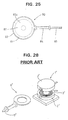
- This system is such as shown in FIG. 28 that a secondary coil unit 1' is arranged on a body of an electric automotive vehicle, a primary coil unit 6' connected with a charging power source 5' is set in the secondary coil unit 1' to attain an electromagnetically connected state, and an alternating current is caused to flow in the primary coil unit 6' to generate a power in the secondary coil unit 1'.
- the secondary coil unit 1' of the prior art is constructed by a pair of container-shaped cores 2' each having an open surface and fitted with a secondary coil 3'.
- the cores 2' are opposed to each other such that a gap for the insertion of the primary coil unit 6' is defined between the open surfaces of the cores 2'.
- the secondary coil unit 1' Since two each of the cores 2' and the secondary coils 3' are essential for the construction of the secondary coil unit 1', the secondary coil unit 1' disadvantageously becomes large and heavy. Further, since the primary coil unit 6' is inserted between the identical assemblies of the secondary coil unit 1', it is necessary to simultaneously and properly control gaps between the primary coil unit 6' and the two identical assemblies in order to improve the power transmitting efficiency. Such a gap control is very difficult because it is likely to bring about a situation where the optimization of one gap leads to an improper control of the other gap, and accordingly the power transmitting efficiency cannot be improved.
- an object of the present invention is to provide a connection system and a connection method, which are capable of easily charging an electric automotive vehicle and are suited to charging an electric automotive vehicle at home.
- connection system according to claim 1 and by a connection method according to claim 16.
- Preferred embodiments of the invention are subject of the dependent claims.
- a connection system for charging a battery or drive battery of an electric automotive vehicle used to drive the vehicle comprising a primary coil unit connected or connectable with an external power source and a secondary coil unit connected or connectable with a battery or a load, preferably provided in a vehicle, wherein the primary coil unit can be electromagnetically coupled or connected with the secondary coil unit for inducing a current in the secondary coil unit.
- the primary coil unit is displaceable, preferably in substantially upward and downward directions, so as to conform to the position, preferably a height from the ground of a parking space, of the secondary coil unit.
- the primary coil unit preferably connected with a charging power source, is so provided as to substantially project from a wall surface, in particular arranged at an angle different from 0° or 180°, preferably substantially normal to a parking space, wherein the primary coil is insertable into a receptacle provided in proximity of the secondary coil unit, preferably in a substantially lateral or front or rear surface or surface of the vehicle, in particular as the vehicle approaches the wall surface of the parking space.
- the primary coil unit comprises a primary coil being accommodated in a protection casing and a support base, and wherein preferably the leading end of the protection casing is made displaceable
- bearing holes for bearing the support shaft are formed substantially larger than the support shaft and/or wherein the leading end of the protection casing is made displaceable by loosely fitting the support shaft in the bearing holes.
- a slanted surface is formed at a leading end of the primary coil unit so as to taper the primary coil unit in a coupling or insertion direction.
- a guide slanted surface is formed at a front opening edge of the receptacle into which the primary coil unit is insertable so as to make the opening area larger along a direction of insertion.
- the primary and/or secondary coil units are constructed by winding a coil around a core having preferably only one magnetically open surface, which preferably can be opposed to the magnetically open surface of the opposite core, wherein the primary and secondary coil units are preferably so set that the open surfaces of the respective cores are arranged, preferably laterally slid, to be opposed to each other.
- connection system further comprises a biasing member, preferably provided in connection with the secondary coil unit, in particular at the vehicle, for biasing the primary coil unit and the secondary coil unit so as to attain a specified substantially opposed state.
- a biasing member preferably provided in connection with the secondary coil unit, in particular at the vehicle, for biasing the primary coil unit and the secondary coil unit so as to attain a specified substantially opposed state.
- connection system further comprises a guiding means, preferably a wheel guide means, provided in connection with the primary coil unit, preferably on the ground, for guiding the secondary coil unit, in particular the vehicle, toward the electromagnetical coupling position of the primary and secondary coil units.
- a guiding means preferably a wheel guide means, provided in connection with the primary coil unit, preferably on the ground, for guiding the secondary coil unit, in particular the vehicle, toward the electromagnetical coupling position of the primary and secondary coil units.
- the primary coil unit is provided in a parking space or a parking lot, a garage, a gas station or the like of the vehicle
- the secondary coil unit is provided in a vehicle
- a vehicle position detecting means for detecting that the primary and secondary coil units are in their electromagnetically connectable or couplable positions
- a charging control circuit for exciting the primary coil unit by means of the power source on condition that the vehicle position detecting means detects that the vehicle is in a predetermined or predeterminable position.
- a charging control circuit for controlling the exciting of the primary coil unit comprises a remaining capacity detecting means for detecting a remaining capacity of the battery, and preferably excites the primary coil unit on condition that the remaining capacity detected by the remaining capacity detecting means is equal to or smaller than a predetermined or predeterminable value.
- a display means for displaying a charging or charged state corresponding to the remaining capacity of the battery is provided, preferably in the parking space and/or on the vehicle.
- connection system further comprises an identification code transmitting means provided in connection with the secondary coil unit, in particular provided in the vehicle, and an identification code checking means provided in connection with the primary coil unit, in particular provided in the parking space, for comparing an identification code received from the identification code transmitting means with a prestored identification code, wherein preferably a charging control circuit excites the primary coil unit on condition that the identification codes compared by the identification code checking means agree.
- the secondary coil unit comprises a receptacle for substantially receiving the primary coil unit and the primary coil unit comprises a handle for the insertion of the primary coil unit into the receptacle preferably by hand.
- connection method for charging a battery or drive battery of an electric automotive vehicle used to drive the vehicle comprising the steps of: electromagnetically coupling a primary coil unit connected or connectable with an external power source with a secondary coil unit connected or connectable with a battery and/or a load, and inducing a current from the primary coil unit in the secondary coil unit.
- the electromagnetic coupling step comprises the step of moving the secondary coil unit, in particular by moving the vehicle, to couple the primary and secondary coils unit.
- the electromagnetic coupling step comprises the step of substantially opposing magnetically open surfaces of the primary and secondary coil units, and/or the step of laterally sliding the primary and/or secondary coil unit toward each other.
- an electromagnetic induction apparatus is connected by parking the vehicle in a predetermined position of a parking space to supply a power from a charging power source installed in the parking space to the battery of the vehicle.
- the electromagnetic induction apparatus is connected by a usual action of parking the vehicle in the predetermined position to supply a power from the charging power source installed in the parking space to the battery. Accordingly, unlike the prior art, an operation of fittably connecting the connectors can be dispensed with and the charging can very easily be performed.
- connection system or charging system preferably comprises:
- the charging control circuit preferably comprises a remaining capacity detecting means for detecting a remaining capacity of the battery, and excites the primary coil on condition that the remaining capacity detected by the remaining capacity detecting means is equal to or smaller than a predetermined value.
- the charging is performed when the remaining capacity of the battery is small, and not when the remaining capacity thereof is large. Accordingly, the battery can be charged in proper quantities, obviating the need for worrying about the remaining capacity.
- the charging control circuit preferably comprises a remaining capacity detecting means for detecting a remaining capacity of the battery, and a display means for displaying a charged state corresponding to the remaining capacity of the battery is preferably provided in the parking space. This construction is convenient because the charged state of the battery can be confirmed outside the vehicle.
- an identification code transmitting means is preferably provided in the vehicle, and the charging control circuit excites the primary coil on condition that it receives a specified identification code.
- the charging is started only when the vehicle which transmits the specified identification code is parked. Accordingly, events where the other vehicle is inadvertently charged and the vehicle intruded into the parking space is charged without permission and other undesirable events can securely be prevented.
- a connection system or an electromagnetic connection apparatus provided in a parking space for an electric automotive vehicle for charging a battery of the vehicle, comprising a primary coil unit supported on a wall surface of the parking space and including a primary coil which can be opposed to a secondary coil provided at a front part of the vehicle, wherein the primary coil unit is displaceable upward and downward so as to conform to the height of the secondary coil from the ground of the parking space.
- an electromagnetic connection apparatus used for charging an electric automotive vehicle which is capable of securely establishing an electromagnetic connection when power is supplied to the vehicle.
- the charging of the vehicle can be prepared only by a usual action of parking the vehicle.
- the degree of compression of the suspension spring provided in the vehicle body differs, for example, depending upon the carrying loads of the vehicle, the height of the secondary coil mounted on the vehicle body is expected to slightly vary depending upon the carrying loads.
- Such a change can be compensated by the vertical displacement of the primary coil, with the result that both coils are constantly opposed to each other in a satisfactory manner.
- the electromagnetic connection apparatus preferably comprises a primary coil unit which includes a primary coil connected with a charging power source and is so provided as to project from a wall surface of the parking space, wherein the primary coil unit being insertable into a receptacle provided in the front surface of the vehicle as the vehicle approaches the wall surface of the parking space.
- the primary coil unit is preferably such that the primary coil is accommodated in a protection casing having a support base, and the leading end of the protection casing is preferably made displaceable by supporting the support base on a holder provided at the wall surface of the parking space via an elastic member.
- the leading end of the primary coil unit is displaced, following the position of the front opening of the receptacle of the secondary coil unit. Accordingly, even if the vehicle is parked in a position slightly displaced from the predetermined parking position, the primary coil unit compensates for this displacement so as to be inserted into the secondary coil unit.
- the primary coil unit is preferably such that the primary coil is accommodated in a protection casing having a support base, and the leading end of the protection casing may be made displaceable by rotatably mounting the support base on a holder provided at the wall surface of the parking space via a support shaft and by providing elastic members between the support base and inner surfaces of the holder before and after the support shaft.
- the leading end of the primary coil unit is displaced, following the position of the front opening of the receptacle of the secondary coil unit so that the primary coil unit can securely be inserted into the secondary coil unit. Further, since the primary coil unit is supported on the holder via the support shaft, the primary coil is more stably positioned and has a better durability as compared with the case where it is supported only via the elastic member.
- bearing holes for bearing the support shaft may be formed larger than the support shaft and the leading end of the protection casing may be made displaceable by loosely fitting the support shaft in the bearing holes.
- the primary coil unit can make not only a pivotal movement about the support shaft, but also a pivotal movement in the plane including the support shaft. Accordingly, the primary coil unit can be displaced upward, downward, to the left and to the right while being stably supported by the support shaft. As a result, both coils can more securely be connected.
- Both coils can further more securely be connected by tapering the primary coil unit toward the leading end thereof and by forming a guide slanted surface at the front opening edge of the receptacle of the secondary coil unit.
- a connection system or charging system for an electric automotive vehicle comprises:
- connection or charging system for an electric automotive vehicle which includes a smaller and lighter secondary coil unit mountable on the vehicle and is capable of maintaining a high power transmitting efficiency between the primary and secondary coil units.
- the secondary coil unit can be, as a whole, made smaller and lighter since it is constructed by the single core and the single coil. Further, since only one magnetic gap is formed between the primary and secondary coil units, the gap can easily be controlled. By properly controlling the gap, the power transmitting efficiency can be maintained at a high level.
- the coil units have a flat shape. Since the respective cores are substantially opposed to each other by laterally sliding the secondary coil unit according to the present invention, an insertion path for bringing the secondary coil unit to be opposed to the primary coil unit can be made smaller. This is advantageous in the construction and/or design of the electric automotive vehicle, e.g. since only a reduce frontal surface is required for the connection system.
- the primary coil unit is provided at a parking space for the vehicle
- the secondary coil unit is provided at a front or rear part of the vehicle
- the open surface of the core of the secondary coil unit is laterally slid with respect to the open surface of the core of the primary coil unit to be opposed thereto by parking the vehicle in a predetermined position of the parking space.
- the coil units can be set in their specified electromagnetic connection positions, taking advantage of a usual action of driving the vehicle forward or backward to park it in a predetermined position. Accordingly, the operation for the charging can be simplified.
- the primary coil unit comprises the core, a primary coil and a protection casing having a support base and adapted to accommodate the core and the primary coil, and the leading end of the primary coil unit is made displaceable by supporting the support base on a holder provided at a wall surface of the parking space via an elastic member.
- the leading end of the primary coil unit can be made displaceable so as to conform to the position of the secondary coil unit. Accordingly, even if the vehicle is parked in a position slightly displaced from the predetermined charging position, the primary coil unit is moved to compensate for this displacement, and reaches a position for the electromagnetic connection with the secondary coil unit.
- the primary coil unit comprises the core, a primary coil and a protection casing having a support base and adapted to accommodate the core and the primary coil, the support base is rotatably supported on a holder provided at a wall surface of the parking lot via a support shaft, and the leading end of the primary coil unit is made displaceable by arranging elastic members between the support base and inner surfaces of the holder before and after the support shaft.
- the leading end of the primary coil unit is displaced to conform to the position of the secondary coil unit, with the result that the primary coil unit is securely moved to the position for the electromagnetic connection with the secondary coil unit.
- the primary coil unit is supported on the holder via the support shaft, the primary coil unit is more stably positioned and has a better durability as compared to the case where the primary coil unit is supported only by the elastic members.
- the leading end of the primary coil unit is made displaceable by forming bearing holes for bearing the support shaft larger than the support shaft and loosely fitting the support shaft in the bearing holes.
- the primary coil unit can make not only a pivotal movement about the support shaft, but also a pivotal movement in the plane including the support shaft. Accordingly, the primary coil unit can be displaced upward, downward, to the left and to the right while being stably supported by the support shaft. As a result, both coils can more securely be connected.
- a slanted surface may be formed at the leading end of the primary coil unit so as to taper the primary coil unit toward the leading end thereof, and/or the secondary coil unit may comprise a receptacle for receiving the primary coil unit and a guide slanted surface may be formed at the front opening of the receptacle so as to make the opening area larger along a direction toward the front.
- the charging system further comprises a biasing member provided at the vehicle for biasing the primary coil unit toward the secondary coil unit so as to attain a specified opposed state.
- the specified opposed state e. g. the gap of specified distance can be attained between the coils, thereby establishing a stable and secure electromagnetically connected state.
- the secondary coil unit comprises a receptacle for receiving the primary coil unit and the primary coil unit comprises a handle for the insertion of the primary coil unit into the receptacle by hand.
- the primary coil unit can be gripped by hand to be set in the position for the electromagnetic connection with the secondary coil unit. Accordingly, the overall construction can be considerably simplified and inexpensively manufactured.
- FIGS. 1 to 5 a first embodiment of the invention is described with reference to FIGS. 1 to 5.
- FIG. 1 shows an electric automotive vehicle E being advanced in a parking space.
- a primary coil unit 30 partly constructing an electromagnetic induction apparatus projects forward from a wall surface W of the parking space.
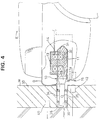
- the primary coil unit 30 is such that a substantially flat plate-shaped primary coil 31 formed by winding a wire around a magnetic core 32 e.g. of ferrite is accommodated in a protection casing 33 of, e.g. synthetic resin.
- a support base 34 is integrally or unitarily provided at one end of the protection casing 33.
- a pair of support shafts 35 project from the support base 34 along a lateral direction (vertical direction in FIG. 2).
- the leading end of the protection casing 33 is tapered, forming an arch-shaped surface 33a.
- a holder 36 is embedded in the wall surface W of the parking space, and the support base 34 of the protection casing 33 is inserted into the holder 36.
- Bearing holes 36a for bearing the support shafts 35 are formed in the inner walls of the holder 36 so that the protection casing 33 is pivotally supported along the vertical direction (directions of arrows A of FIG. 3) about the support shafts 35. Since the bearing holes 36a are sufficiently larger than the support shafts 35 so as to support the support shafts 35 with a relatively large play, the leading end of the protection casing 33 makes a pivotal movement along the substantially horizontal direction, i.e. along directions of arrows B of FIG. 2.
- the protection casing 33 is elastically supported along the horizontal direction and projects at an angle different from 0° or 180° to the wall surface W, in particular substantially normally projects in a direction substantially normal to the wall surface W as indicated by solid line in FIG. 2, in particular in a standby or rest position.
- a force acts sideways on the leading end of the protection casing 33 in the solid line state of FIG. 2, the protection casing 33, or the primary coil unit 30 makes a reciprocal pivoting movement substantially along the horizontal direction. Further, as shown in FIG.
- a total of four compression springs 38 are provided before and after the support shafts 35 between the upper and lower surfaces of the support base 34 and the upper and lower inner side walls of the holder 36. Accordingly, the protection casing 33 is elastically supported along the vertical direction and normally projects in the direction normal to the wall surface W as shown in FIG. 3. When a vertically acting force is exerted on the leading end of the protection casing 33 in a solid line state of FIG. 3, the protection casing 33, or the primary coil unit 30 pivots upward and downward.
- a secondary coil unit 10 is provided at a vehicle E, preferably at a front bottom part of the vehicle E.
- the secondary coil unit 10 is such that a substantially flat plate-shaped secondary coil 14 formed by winding a wire around a magnetic core 13 of, e.g. ferrite is arranged at the upper surface of a receptacle 11 for substantially receiving the primary coil unit 30.
- the primary and secondary coils 31, 14 constructing the electromagnetic induction apparatus are brought into an electromagnetically connected state, where preferably the magnetic cores 13, 32 of the coils 31, 14 are substantially coaxially located.
- the receptacle 11 is made of, e.g.
- a guide slanted surface 11a is formed so as to make the area of the opening larger along the direction toward the front. Accordingly, the leading end of the protection casing 33 can easily be guided.
- a shock absorbing material 39 is arranged around the primary coil unit 30 on the wall surface W of the parking space. An impact produced when a front bumper B of the vehicle E comes into contact is absorbed by the shock absorbing material 39.
- a pressure switch 40 is embedded in the shock absorbing material 39. Alternatively a proximity switch may be used. When the vehicle E moves forward to a position where the protection casing 33 of the primary coil unit 30 is completely accommodated in the receptacle 11 and the front bumper B strikes against the shock absorbing material 39, the pressure switch 40 is turned on. This pressure switch 40 or proximity switch functions as a vehicle position detecting means.
- a stop lamp 41 is mounted at an upper part of the wall surface W of the parking space. The stop lamp 41 is turned on when the pressure switch 40 operates.
- an infrared communication device 42 is mounted below the primary coil unit 30.
- the infrared communication device 42 faces an infrared communication device 15 provided at a lower part of the front bumper B of the vehicle E.
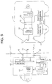
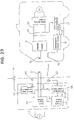
- a power supply circuit 44 provided in the parking space is connected with the primary coil 31.
- the power supply circuit 44 supplies a high frequency current of, e.g. 40 kHz to the primary coil 31 by suitably shaping, e.g. by rectifying and/or switching a commercial power source 45.
- a vehicle position detecting circuit 46 detects that the vehicle E has parked in the specified position upon receipt of a signal from the pressure switch 40. Based on this detection, the detecting circuit 46 turns the stop lamp 41 on and outputs a vehicle detection signal Sev to a charging control circuit 47.
- the charging control circuit 47 Upon receipt of the signal Sev from the vehicle position detecting circuit 46 and a capacity shortage signal Scg from a communication control circuit 48, the charging control circuit 47 actuates the power supply circuit 44 to excite the primary coil 31.
- the communication control circuit 48 is connected with the infrared communication device 42, and receives an information concerning the charging from a capacity detecting circuit via the infrared communication device 15 and a communication control circuit 16 of the vehicle E.
- a charging circuit 18 is connected with the secondary coil 14 to charge a battery 19.
- the charging circuit 18 rectifies an ac current induced in the secondary coil 14 and generates a dc voltage necessary to charge the battery 19.
- a motor driving circuit 21 is connected with the battery 19 via a main switch 20 for driving a drive motor 22 of the vehicle E.
- a remaining capacity detecting circuit 17 receives an information concerning the remaining capacity of the battery 19 via an output line of the battery 19. For example, the remaining capacity detecting circuit 17 estimates the remaining capacity of the battery 19 by adding up consumed power based on the current having flowed in the output line, and outputs the capacity shortage signal Scg when the estimated remaining capacity falls short of a predetermined value.
- the remaining capacity detecting circuit 17 also receives, from the charging circuit 18, an information concerning a charge current flowed into the battery 19; estimates a remaining capacity increasing by the charging based on the received information; and stops outputting the capacity shortage signal Scg when the estimated remaining capacity reaches the predetermined rated value.
- the remaining capacity detecting circuit 17 may directly measure the remaining capacity of the battery 19, e.g. basing upon variations of inductance or capacity of the battery 19.
- the remaining capacity detecting circuit 17 may also measure a temperature of the battery 19 for determining the remaining capacity, at least as a factor for such a determination.
- the vehicle E is slowly advanced toward the wall surface W in the parking space.
- the primary coil unit 30 projecting from the wall surface W is fitted into the receptacle 11 at the front part of the vehicle E.
- the front bumper B of the vehicle E presses the pressure switch 40, thereby operating the same.
- the stop lamp 41 is turned on in response to the signal from the vehicle position detecting circuit 46. If the vehicle E is stopped in this position, the primary coil 31 is coaxially located with the secondary coil 14 in the receptacle 11, being enabled to be electromagnetically connected with the secondary coil 14.
- the vehicle position detecting circuit 46 outputs the vehicle detection signal Sev to the charging control circuit 47.
- the capacity shortage signal Scg is sent to the charging control circuit 47 from the remaining capacity detecting circuit 17 via the infrared communication devices 15, 42, with the result that the power supply circuit 44 operates to excite the primary coil 31.
- a voltage is generated in the secondary coil 14 by an electromagnetic induction phenomenon, and the charging circuit 18 charges the battery 19 of the vehicle E with the generated voltage.
- the output of the capacity shortage signal Scg is stopped.
- the excitation of the primary coil 31 by the charging circuit 18 is stopped, completing the charging.
- the primary and secondary coils 31, 14 are connected only by a usual action of parking the vehicle E in the specified position of the parking space, and power is supplied to the charging circuit 18 of the vehicle E from the commercial power source 45 in the parking space to charge the battery 19, completely obviating need for the engagement of the connectors as in the prior art. Therefore, the charging system according to this embodiment enables a remarkably easy charging and is also very suited to the use at home.
- the second embodiment is similar to the first embodiment except that a display means for displaying a charged state corresponding to the remaining capacity of the battery 19 is additionally provided in the parking space. Accordingly, no repetitive description is given on the identical or similar construction by identifying the same elements by the same reference numerals, and only a different construction is described with reference to FIG. 6.
- a display unit 60 which is controllably turned on by a display control circuit 61.
- the display unit 60 includes a stop lamp 41 and a remaining capacity indicator 62 formed e.g. by vertically arranging a plurality of LEDs.
- a remaining capacity detecting circuit 63 provided in an electric automotive vehicle E constantly detects the remaining capacity of a battery 19 being charged and sends the detection data to the display control unit 61 via infrared communication devices 15, 42 to make a display corresponding to the detected remaining capacity in the capacity indicator 62.
- a display in proportion to the remaining capacity is made in this embodiment: all LEDs of the capacity indicator 62 are turned on when the battery 19 is fully charged, and half the number of LEDs are turned on when the battery 19 is half charged. Such a display is convenient because the remaining capacity of the battery 19 being charged is easily visible.
- the third embodiment is similar to the first embodiment except that the charging is performed only when identification (ID) codes of the vehicle agree. Accordingly, no repetitive description is given on the identical or similar construction by identifying the same elements by the same reference numerals, and only a different construction is described with reference to FIG. 7.
- An electric automotive vehicle E is provided with an ID code transmitting circuit 70 which is connected with a communication control circuit 16.
- an ID code checking circuit 71 which is connected with a communication control circuit 48 and a charging control circuit 47.
- the ID checking circuit 71 Upon recept of a vehicle detection signal Sev from a vehicle position detecting circuit 46, the ID checking circuit 71 sends a signal to the ID transmitting circuit 70 of the vehicle E via infrared communication devices 15, 42, causing the ID transmitting circuit 70 to respond by sending an ID code peculiar to the vehicle E via the infrared communication devices 15, 42. If the received ID code agrees with the code stored in the ID code checking circuit 71, the ID code checking circuit 71 outputs an agreement signal Ssm to the charging control circuit 47.
- the charging control circuit 47 starts the excitation of the primary coil 31 on condition that it received the vehicle detection signal Sev, the capacity shortage signal Scg and the agreement signal Ssm.
- the charging is not started unless the ID code from the vehicle E agrees with the ID code stored in advance in the ID code checking circuit 71. Accordingly, a possibility that the other's car parked in the parking space is charged, or the other's car is intruded into the parking space and charged without permission can securely be prevented.
- the fourth embodiment differs from the first to third embodiments in that the primary and secondary coils 31, 14 are so positioned as to establish an electromagnetic connection after the vehicle E is parked in the parking space.
- the fourth embodiment is described with reference to FIGS. 8 to 11.
- a coil positioning apparatus 50 is provided in the wall surface W of the parking space, and a primary coil 31 is supported such that its electromagnetic connection surface faces forward.
- a secondary coil 14 is mounted such that its electromagnetic connection surface substantially faces in a direction toward the wall surface W, e.g. substantially forward as shown in FIG. 10.
- the coil positioning apparatus 50 substantially horizontally moves the primary coil 31 by a so-called ball screw mechanism to a position where it is electromagnetically connectable with a secondary coil 14 by detecting the positional relationship of the primary and secondary coils 31, 14 by sensors 43.
- the ball screw mechanism of the coil positioning apparatus 50 includes a substantially horizontally extending support rail 51, a ball screw 55 provided along the support rail 51, and a support member 52 which is movably supported on the support rail 51 and spirally fitted to the ball screw 55.
- the support rail 51 is such that a substantially horizontally extending slit 51a is formed e.g. in the middle of a plate member and the portions of the plate member above and below the slit 51a construct a pair of rails.
- the slit 51a is preferably formed such that the spacing between the pair of rails widens in a stepwise manner toward the front surface as shown in FIG. 9.
- the support member 52 includes a substantially flat disk--shaped portion for accommodating the primary coil 31, a substantially rectangular beam 52a extending from the back of the disk--shaped portion, and a tubular internally threaded portion 56 provided at the leading end of the rectangular beam 52a so as to be spirally engageable with the ball screw 55.
- An integral assembly of the disk-shaped portion and the rectangular beam 52a has such a vertical cross section as to be fittable in the slit 51a of the support rail 51 in which the width is preferably widened in a stepwise manner toward the front surface.
- the ball screw 55 is so arranged as to face the slit 51a at the back of the support rail 51, and is spirally engaged with the internally threaded portion 56 projecting backward.
- the opposite ends of the ball screw 55 are rotatably supported by bearings 51b projecting backward from the opposite ends of the support rail 51.
- To one end of the ball screw 55 is coupled a drive shaft of a motor 57 fixed to the support rail 51.
- Sensors 43 are embedded in the opposite sides of the disk--shaped portion of the support member 52 with the primary coil 31 therebetween as shown in FIG. 10.
- the sensors 43 operate upon detecting a signal or light from signal or light emitters (43a in FIG. 10) which are provided on the opposite sides of the secondary coil 14 of the vehicle E so as to face the sensors 43.
- signal or light emitters 43a in FIG. 10
- the electro-magnetic connection surfaces of the primary and secondary coils 31, 14 are substantially opposed to each other.
- the signal or light emitters of the vehicle E emit signals or light for a predetermined time measured by, e.g. a timer.
- the coils 31, 14 are positioned by the sensors 43 and the ball screw mechanism as follows.
- the support member 52 is positioned at one end of the support rail 51.
- the motor 57 is stopped when the sensors 43 both operate while the support member 52 is moving toward the other end.
- the coils 31, 14 are held with the electromagnetic surfaces thereof substantially opposed to each other. For example, if the vehicle E is obliquely parked, making it impossible to electromagnetically connect the coils 31, 14, the sensors 43 do not operate while the support member 52 is moving toward the other end. In such a case, the driver is notified that the electromagnetic connection is unattainable by, e.g. activating a buzzer or changing the color of a stop lamp.
- the driver may reattempt to park the vehicle E in the proper charging position.
- the coil positioning apparatus 50 thus constructed is mounted on the wall surface W of the parking space via a shock absorbing material 39, and the support rail 51 slightly projects from the wall surface W.
- the apparatus 50 is mounted at such a height that the primary coil 31 is substantially on a level with the secondary coil 14 of the vehicle E.
- a proximity or pressure switch 40 is embedded in the shock absorbing material 39 so as to detect that the support rail 51 is pressed by the vehicle E.
- a stop lamp 41 is turned on as in the first embodiment and the coil positioning apparatus 50 is activated.
- the vehicle E is slowly advanced in the parking space until a bumper B comes into contact with the support rail 51 projecting from the wall surface W.
- the pressure switch 40 in the shock absorbing material 39 operates, thereby turning the stop lamp 41 on.
- the driver signalled by the stop lamp 41 stops the vehicle E (FIG. 10).
- the secondary coil 14 of the vehicle E is located adjacent to a moving path of the primary coil 31 of the coil positioning apparatus 50.
- the coil positioning apparatus 50 starts operating in response to the operation of the pressure switch 40.
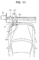
- the motor 57 is driven to move the primary coil 31 at the one end of the support rail 51 toward the other end.
- the motor 57 is stopped to hold the primary and secondary coils 31, 14 in the electromagnetically connectable position (FIG. 11).
- the battery 19 is charged in the same manner as in the first embodiment.
- the driver only needs to bring the bumper B into contact with the coil positioning apparatus 50 while parking the vehicle E. Thereafter, the coil positioning apparatus 50 positions the coils 31, 14 for the electromagnetic connection. Therefore, the charging can be very easily performed regardless of the driving technique of the driver.
- the primary coil 31 may, for example, be moved by a timing belt mechanism 58 as shown in FIG. 12.
- a means for supporting the primary coil 31 may be constructed by a rail 59a and a slider 59b as shown in FIG. 13.
- the sensors 43 are used to detect that the coils 31, 14 are in their electromagnetically connectable positions in this embodiment.
- the position detecting means may, for example, detect a displacement of the coils 31, 14. In such a case, the coils 31, 14 are substantially opposed to each other by moving the primary coil 31 by the detected displacement.
- a coil positioning apparatus 80 which is fixed to the wall surface W in the fourth embodiment, is supported inclinably with respect to the wall surface W in a horizontal plane via elastic support mechanisms 90 so that the coils can automatically be positioned along the lateral direction and automatically be substantially opposed in parallel to each other.
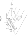
- the fifth embodiment is described with reference to FIGS. 14 to 18.
- the coil positioning apparatus 80 includes a laterally long housing 81 as shown in FIG. 14 or 15.
- a support rail 51, a ball screw 55 and the like are accommodated in the housing 81 so as to render the same function as the coil positioning apparatus 50 described in the fourth embodiment.
- An unillustrated pressure switch 40 is provided in the housing 81 to detect that the support rail 51 provided at the front surface of the housing 81 is pressed. Further, an infrared communication device (not shown) is provided in a specified position of the lower part of the housing 81 to obtain pieces of necessary information such as a charged amount of the vehicle E.
- the housing 81 is mounted on the wall surface W of the parking space via the elastic support mechanisms 90 which include each a support bracket 91 extending from the back surface of the housing 81 and a strut 92 projecting from the wall surface W of the parking space.
- the struts 92 of the mechanisms 90 are placed apart side by side along the horizontal direction by the same distance as the support brackets 91 of the mechanisms 90.
- each strut 92 is substantially U-shaped and separated into two parts: upper and lower parts, and a shaft 94 is mounted through these upper and lower parts and the support bracket 91 disposed between the upper and lower parts.
- Through holes formed in the strut 92 through which the shaft 94 is inserted have the same diameter as the shaft 94, but through holes formed in support bracket 91 are oblong holes so as to permit the support bracket 91 to move along forward and backward directions with respect to the shaft 94.
- the support bracket 91 is pivotally and slidably coupled with the leading end of the strut 92 via the shaft 94.
- the support bracket 91 is also inclinable because the shaft 94 can be inclined in the oblong holes.
- the opposite ends of the shaft 94 are secured by, e.g. clips, nuts or the like.
- the struts 92 and the support brackets 91 coupled as described above are biased in a projecting direction by compression coil springs 93 fitted thereon. Accordingly, the support brackets 91 are securely and stably held in their projected positions, and act as follows. For example, if the vehicle E is obliquely parked, one end of the bumper B comes into contact with one end of the coil positioning apparatus 80. Thus, only the elastic support mechanism 90 at the side pressed by the bumper B slides, and the one at the other side rotates, with the result that the coil positioning apparatus 80 is inclined with respect to the wall surface W along the horizontal plane so that the bumper B of the vehicle E and the coil positioning device 80 are opposed in parallel to each other.
- both elastic support mechanisms 90 make a sliding movement and the shock is absorbed by the compression coil springs 93. Further, since the elastic support mechanisms 90 are inclinable along the forward and backward directions, they are capable of bringing the coil positioning apparatus 80 and the bumper B into close contact by offsetting the inclinations of the coil positioning apparatus 80 and the bumper B along the forward and backward directions.
- the vehicle E is provided with a secondary coil 14 at its front surface.
- the electromagnetic connection surface of the secondary coil 14 is oriented in conformity with a contact surface of the bumper B with the coil positioning apparatus 80. Accordingly, if the coil positioning apparatus 80 and the bumper B are opposed in parallel to each other as described above, the electromagnetic connection surfaces of the coils 31, 14 are opposed in parallel to each other. Further, since the coil positioning apparatus 80 is inclinable along the forward and backward directions as described above, if the contact surface of the bumper B is inclined, the electromagnetic connection surface of the secondary coil 14 may be accordingly inclined.
- the vehicle E is advanced in the parking space to bring the bumper B into contact with the coil positioning apparatus 80 projecting from the wall surface W.
- the vehicle E is stopped when a stop lamp 41 is turned on in response to a pressure switch 40.
- the elastic support mechanisms 90 act to offset the resulting inclination, thereby allowing the bumper B of the vehicle E to face the coil positioning apparatus 80 substantially straight. Accordingly, the driver needs not consider an angle of the vehicle with respect to the coil positioning apparatus 80. Thus any inclination of the vehicle E with respect to the coil positioning apparatus 80 can be compensated for.
- the coil positioning apparatus 80 starts operating in response to the pressure switch 40, thereby guiding the primary coil 31 to a position where it is electromagnetically connectable with the secondary coil 14 in the same manner as in the fourth embodiment for the charging.
- the bumper B of the vehicle E and the coil positioning apparatus 80 face substantially straight each other, the coils 31, 14 can constantly brought to their proper electromagnetically connectable positions. Therefore, the charging can efficiently be performed.
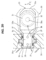
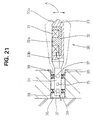
- FIGS. 19 to 23 a sixth embodiment of the invention is described with reference to FIGS. 19 to 23.
- FIG. 19 shows an electric automotive vehicle E being advanced in a parking space.
- a primary coil unit 30 partly constructing an electromagnetic induction apparatus projects forward from a wall surface W of the parking space.
- the primary coil unit 30 is such that a primary coil 31 contained in a core 32 of, e.g. ferrite is accommodated in a protection casing 33 of, e.g. hard synthetic resin.
- the core 32 has a substantially flat circular container-like shape having only one open surface (upper surface) and is formed with a circular column 32a in its center.
- the primary coil 31 is wound around the circular column 32a.
- the open upper surface of the protection casing 33 is covered by a smooth protection film 33b of specified thickness which sealably attaches to the core 32, so that the core 32 and the primary coil 31 are sealed.
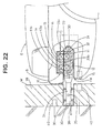
- the secondary coil unit 10 is provided at a front bottom part of the vehicle E.
- the secondary coil unit 10 is constructed by containing a secondary coil 14 in a core 13 of, e.g. ferrite and is provided at an upper part of a receptacle 11 for receiving the primary coil unit 30.
- the core 13 has a shape obtained by inverting the core 32 of the primary coil unit 30, i.e. a flat circular container-like shape having only one open surface (lower surface) and is formed with a circular column 13a in its center. Further, the open lower surface of the core 13 is covered by a smooth protection film 11b of specified thickness which sealably attaches to the core 13, so that the core 13 and the secondary coil 14 are sealed.
- an arch-shaped leaf spring 12 corresponding to a biasing member is provided.
- the leaf spring 12 biases the protection casing 33 upward to bring the primary and secondary coil units 10, 30 into close contact via the two protection films 11b, 33b.
- the coils 31, 14 are electromagnetically connected with the cores 13, 32 coaxially located.
- the other elements are substantially similar or the same as in the previous embodiments.
- the vehicle E is slowly advanced toward the wall surface W in the parking space.
- the primary coil unit 30 projecting from the wall surface W is fitted into the receptacle 11 at the front part of the vehicle E.
- the front bumper B of the vehicle E presses the pressure switch 40, thereby operating the same.
- the stop lamp 41 is turned on in response to the signal from the vehicle position detecting circuit 46. The driver may stop the vehicle E in this position.
- the open surface of the core 32 of the primary coil unit 30 is laterally slid with respect to the open surface of the core 13 of the secondary coil unit 10, and the core 32 of the primary coil unit 30 comes to be coaxially opposed to the core 13 of the secondary coil unit 10 in the receptacle 11.
- the primary coil unit 30 is biased toward the secondary coil unit 10 by the leaf spring 12 provided in the receptacle 11, with the result that the coils 14, 31 are brought into close contact via the two thin protection films 11b, 33b and electromagnetically connectable with each other. Since the protection films 11b, 33b are both smooth and of specified thickness, the gap between the cores 13, 32 are constantly fixed, ensuring a stable electromagnetically connected state.
- the vehicle position detecting circuit 46 outputs the vehicle detection signal Sev to the charging control circuit 47.
- the capacity shortage signal Scg is sent to the charging control circuit 47 from the remaining capacity detecting circuit 17 via the infrared communication devices 15, 42, with the result that the power supply circuit 44 operates to excite the primary coil 31.
- a voltage is generated in the secondary coil 14 by an electromagnetic induction phenomenon, and the charging circuit 18 charges the drive battery 19 of the vehicle E with the generated voltage.
- the output of the capacity shortage signal Scg is stopped.
- the excitation of the primary coil 31 by the charging circuit 18 is stopped, completing the charging.
- the primary and secondary coils 31, 14 are connected only by a usual action of parking the vehicle E in the specified position of the parking space, and power is supplied to the charging circuit 18 of the vehicle E from the commercial power source 45 in the parking space to charge the drive battery 19. Therefore, the charging system according to this embodiment enables a remarkably easy charging and is very suited to the use at home.
- the construction of the secondary coil unit 10 by the single core 13 and the single coil 14 makes the secondary coil unit 10 as a whole smaller and lighter. This makes the vehicle lighter, thereby contributing to an improvement in drive performance. Further, since only one magnetic gap between the coil units 10 and 30 is formed between the opposite surfaces of the cores 13 and 32, the gap can easily be controlled. For example, this gap can be held fixed by a simple construction that the primary coil unit 30 is biased toward the secondary coil unit 10 by the leaf spring 12 as in this embodiment. As a result, the power transmitting efficiency between the coil units 10 and 30 can be maintained at a high level. Therefore, generation of heat and power loss can advantageously be suppressed low despite the charging for a long time.
- the secondary coil unit 10 is laterally slid to substantially oppose the cores 13, 32 to each other, an opening used for the insertion of the secondary coil unit 10 can be minimized despite the fact that the cores 13, 32 have a flat shape in order to reduce a magnetic resistance which will acts in the gap. This feature is advantageous in the construction and/or design of the vehicle E.
- the leaf spring 12 is provided at the bottom of the receptacle 11 to bias the primary coil unit 30 toward the secondary coil unit 10, bringing the coil units 10, 30 into close contact. Accordingly, a gap of specified distance is constantly formed between the coil units 10 and 30 via the protection films 11b, 33b. As a result, a stable electromagnetically connected state can advantageously be attained.
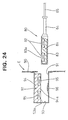
- FIGS. 24 and 25 show an exemplary construction with which a primary coil unit is set in an electric automotive vehicle E by hand.
- a primary coil unit 80 is such that a primary coil 82 is contained in a core 81 having only one surface and the core 81 is accommodated in a protection casing 83. Similar to the first embodiment, the open surface of the core 81 is covered by a smooth protection film 83a.
- a handle 84 for gripping the primary coil unit 81 is integrally or unitarily provided at one end of the protection casing 83.
- a power cable 85 connected with an unillustrated charging power source is drawn through the handle 84.
- an opening 91 is formed in a body 90 of the vehicle E, and a secondary coil unit 92 is provided in the opening 91.
- the secondary coil unit 92 is constructed such that a secondary coil 95 is contained in a core 94 of, e.g. ferrite, and is provided at an upper part of a receptacle 93 for receiving the primary coil unit 80.
- the core 94 has a shape obtained by inverting the core 81 of the primary coil unit 80, i.e. a substantially flat circular container-like shape having only one open surface (lower surface) and is formed with a circular column 94a in its center.
- the open lower surface of the core 94 is covered by a smooth protection film 11b of specified thickness.
- a smooth protection film 11b of specified thickness.
- an arch-shaped leaf spring 96 corresponding to a biasing member is provided.
- the leaf spring 96 biases the primary coil unit 80 upward to bring the primary and secondary coil units 80, 92 into close contact via the two protection films 83a, 93a.
- the coils 82, 95 are electromagnetically connected.
- the primary coil unit 80 when the vehicle E is to be charged, the primary coil unit 80 is inserted into the receptacle 93 of the secondary coil unit 92 by gripping the handle 84. Then, the open surface of the core 81 of the primary coil unit 80 is laterally slid with respect to the open surface of the core 94 of the secondary coil unit 92, and the core 81 of the primary coil unit 80 comes to be coaxially opposed to the core 94 of the secondary coil unit 92 in the receptacle 93.
- the primary coil unit 80 is biased toward the secondary coil unit 92 by the leaf spring 96 provided in the receptacle 92, with the result that the coils 82, 95 are brought into close contact via the two thin protection films 83a, 93a and electromagnetically connectable with each other. Accordingly, similar to the respective foregoing embodiments, the gap between the cores 81 and 94 are constantly fixed, ensuring a stable electromagnetically connected state.
- the primary coil unit may not necessarily constantly project from the wall surface, but may be retracted into the wall surface.
- the front or rear part of the vehicle may be inserted into such a primary coil unit.
- the primary coil unit may be provided with a dust protective cover or a protection cover. Upon detecting a contact or approach of the bumper of the vehicle, this cover is opened to permit the connection with the secondary coil unit.
- FIG. 26 is a perspective view showing an electric automotive vehicle E being advanced into a parking lot equipped with a wheel guide 160 according to an eighth embodiment of the invention.
- the wheel guide 160 includes one, two or more projecting, preferably upstanding substantially L-shaped rails, preferably symmetrically arranged on the ground of the parking lot with their longer sides 160a faced in substantially parallel directions.
- the longer sides 160a are so spaced as to be fittingly located between the left and right wheels of the vehicle E, and have their leading ends bent such that a distance therebetween decreases toward the leading ends.
- Shorter sides may extend in opposite or outward directions from the longer sides 160a and have such a length that the front wheels of the vehicle E can come into contact therewith.
- the vehicle E if the vehicle E is advanced into the parking lot with the longer sides 160a located between the left and right wheels, it stops where the front wheels come into contact with the shorter sides . More specifically, the vehicle E is parked while its orientation and position are determined by the wheel guide 160.
- the pressure sensors 150 detect that the vehicle E has parked along the wheel guide 160, and their detection results are sent to a main controller provided in an external power source unit.
- the vehicle E When the vehicle E is advanced into the parking lot with the longer sides 160a of the wheel guide 160 between the left and right wheels, it is guided with its advancing direction restricted by the longer sides 160a. The vehicle E cannot make any further advance when the front wheels come to positions where they are in contact with the shorter sides or the pressure sensors 150, with the result that a driver can know that the vehicle E is in the charging position.
- a lamp provided at the external power source unit may be turned on. The driver can also know from this lamp that the vehicle E is in the charging position.
- the secondary coil 10 When the vehicle E is stopped in the charging position, the secondary coil 10 is opposed to the primary coil 30.
- the vehicle E can easily be parked in the charging position regardless of the parking technique of the driver.
- the primary coil and the wheel guide may be formed as a single unit and arranged in the parking lot. Further, although the left and right wheels of the vehicle E are guided , the vehicle E may be guided by restricting the opposite side surface of the wheel of the vehicle E at one side by a narrow substantially U-shaped wheel guide 161 as shown in FIG. 26.
- the primary coil unit 10 is substantially coupled or connected with the secondary coil unit 30 provided in the vehicle E.
Priority Applications (3)
| Application Number | Priority Date | Filing Date | Title |
|---|---|---|---|
| DE69714879T DE69714879T2 (de) | 1996-01-30 | 1997-01-29 | Verbindungssystem mit zugehörigem Verfahren |
| EP97101385A EP0788211B1 (de) | 1996-01-30 | 1997-01-29 | Verbindungssystem mit zugehörigem Verfahren |
| US08/791,109 US5850135A (en) | 1996-01-30 | 1997-01-30 | Connecting system and a connection method |
Applications Claiming Priority (13)
| Application Number | Priority Date | Filing Date | Title |
|---|---|---|---|
| JP1403296 | 1996-01-30 | ||
| JP8014032A JPH09213378A (ja) | 1996-01-30 | 1996-01-30 | 電気自動車用充電システム |
| JP14032/96 | 1996-01-30 | ||
| JP01748696A JP3586955B2 (ja) | 1996-02-02 | 1996-02-02 | 電気自動車用充電システム |
| JP1748696 | 1996-02-02 | ||
| JP17486/96 | 1996-02-02 | ||
| JP81750/96 | 1996-04-03 | ||
| JP8175096 | 1996-04-03 | ||
| JP08175096A JP3772997B2 (ja) | 1995-07-31 | 1996-04-03 | 電気自動車用充電システム及び電気自動車充電用電磁結合装置 |
| JP8192187A JPH09102429A (ja) | 1995-07-31 | 1996-07-22 | 電気自動車用充電装置 |
| JP192187/96 | 1996-07-22 | ||
| JP19218796 | 1996-07-22 | ||
| EP97101385A EP0788211B1 (de) | 1996-01-30 | 1997-01-29 | Verbindungssystem mit zugehörigem Verfahren |
Publications (3)
| Publication Number | Publication Date |
|---|---|
| EP0788211A2 true EP0788211A2 (de) | 1997-08-06 |
| EP0788211A3 EP0788211A3 (de) | 1998-02-04 |
| EP0788211B1 EP0788211B1 (de) | 2002-08-28 |
Family
ID=58463524
Family Applications (1)
| Application Number | Title | Priority Date | Filing Date |
|---|---|---|---|
| EP97101385A Expired - Lifetime EP0788211B1 (de) | 1996-01-30 | 1997-01-29 | Verbindungssystem mit zugehörigem Verfahren |
Country Status (3)
| Country | Link |
|---|---|
| US (1) | US5850135A (de) |
| EP (1) | EP0788211B1 (de) |
| DE (1) | DE69714879T2 (de) |
Cited By (16)
| Publication number | Priority date | Publication date | Assignee | Title |
|---|---|---|---|---|
| EP0921607A2 (de) * | 1997-11-21 | 1999-06-09 | Miltronik GmbH & Co. KG | Steckverbindung zum Übertragen von Daten zwischen einer elektrischen Spannungsquelle und einer Datenverarbeitungseinrichtung |
| EP1205340A1 (de) * | 2000-11-10 | 2002-05-15 | Adrian Robert Mould | Ladestation für elektrische Fahrzeuge |
| EP1213818A1 (de) * | 1998-03-24 | 2002-06-12 | Seiko Epson Corporation | Elektronisches vorrichtungsverfahren,verfahren zur regelung einer elektronischen vorrichtung, verfahren zur bestimmung der ladung in wiederaufladbarer batterie sowie verfahren zur ladung einer wiederaufladbaren batterie |
| FR2828589A1 (fr) * | 2001-08-07 | 2003-02-14 | France Telecom | Systeme de connexion electrique entre un vehicule et une station de recharge ou similaire |
| FR2828665A1 (fr) * | 2001-08-09 | 2003-02-21 | Honda Motor Co Ltd | Systeme de chargement pour un petit vehicule a moteur |
| CN101764434A (zh) * | 2008-12-22 | 2010-06-30 | 爱信艾达株式会社 | 受电引导装置 |
| CN102039826A (zh) * | 2009-10-09 | 2011-05-04 | 周良勇 | 为电动汽车提供充电或行驶电力的护栏式供电线路 |
| WO2011110645A3 (de) * | 2010-03-12 | 2012-06-07 | Leopold Kostal Gmbh & Co Kg | Übertragungssystem zum laden der traktionsbatterien eines elektrisch angetriebenen kraftfahrzeugs |
| CN102810898A (zh) * | 2011-05-31 | 2012-12-05 | 通用电气公司 | 用于便携式图像检测器中非接触功率传输的系统和方法 |
| CN103563217A (zh) * | 2011-05-27 | 2014-02-05 | 日产自动车株式会社 | 非接触供电装置、车辆以及非接触供电系统 |
| CN103563216A (zh) * | 2011-05-27 | 2014-02-05 | 日产自动车株式会社 | 非接触供电装置 |
| CN103703650A (zh) * | 2011-07-22 | 2014-04-02 | 奥迪股份公司 | 用于给动力电池充电的方法、用于将能量传输到电动车的装置和汽车 |
| DE102010027670B4 (de) | 2010-07-20 | 2018-10-11 | Siemens Aktiengesellschaft | Vorrichtung und Verfahren zum Anschließen eines elektrischen Energiespeichers an eine Ladestation |
| WO2019060747A3 (en) * | 2017-09-22 | 2019-05-02 | Locus Robotics Corp. | ROBOT LOAD STATION PROTECTION ELEMENT |
| US10906419B2 (en) | 2016-04-01 | 2021-02-02 | Locus Robotics Corp. | Electrical charging system for a robot |
| WO2021219839A1 (de) * | 2020-04-30 | 2021-11-04 | INSTATE GmbH | Bordsteinmodul, bordsteinmodulgruppe, ladestation und verfahren zum betreiben solcher vorrichtungen |
Families Citing this family (138)
| Publication number | Priority date | Publication date | Assignee | Title |
|---|---|---|---|---|
| JPH10322921A (ja) * | 1997-05-15 | 1998-12-04 | Sumitomo Wiring Syst Ltd | 電気自動車充電用磁気結合装置 |
| JP3786392B2 (ja) * | 1998-09-09 | 2006-06-14 | 本田技研工業株式会社 | 電動車両用充電装置 |
| JP2001110659A (ja) * | 1999-10-05 | 2001-04-20 | Toyota Autom Loom Works Ltd | 充電用受電器 |
| US9425638B2 (en) | 1999-11-01 | 2016-08-23 | Anthony Sabo | Alignment independent and self-aligning inductive power transfer system |
| JP2001167959A (ja) * | 1999-12-10 | 2001-06-22 | Toyota Autom Loom Works Ltd | 電磁誘導方式の給電側充電装置及び電磁誘導方式充電装置 |
| US6619342B2 (en) | 2001-05-11 | 2003-09-16 | General Hydrogen Corporation | Wheel stop service port |
| US6817879B2 (en) * | 2001-11-26 | 2004-11-16 | General Hydrogen Corporation | Service port configurations |
| US6722903B2 (en) | 2002-01-10 | 2004-04-20 | General Hydrogen Corporation | Service plug configuration |
| US6691749B2 (en) | 2002-01-10 | 2004-02-17 | General Hydrogen Corporation | Service coupling |
| US7023177B1 (en) * | 2002-11-08 | 2006-04-04 | Amigo Mobility International, Inc. | Rechargeable electric battery powered vehicle for the physically challenged and charge station system, and methods of making and assembling the same |
| US20060273756A1 (en) * | 2005-06-06 | 2006-12-07 | Bowling David A | Opportunity charging system for battery powered mining equipment |
| JP4162026B2 (ja) * | 2006-09-29 | 2008-10-08 | トヨタ自動車株式会社 | 車両充電システム、車両充電装置および電動車両 |
| US20070170886A1 (en) * | 2006-10-03 | 2007-07-26 | Plishner Paul J | Vehicle equipped for providing solar electric power for off-vehicle use and systems in support thereof |
| US7849250B2 (en) | 2006-10-31 | 2010-12-07 | Sonosite, Inc. | Docking station with hierarchal battery management for use with portable medical equipment |
| US20070124036A1 (en) * | 2006-11-06 | 2007-05-31 | Plishner Paul J | Rail vehicle or other path-constrained vehicle equipped for providing solar electric power for off-vehicle use, and systems in support thereof |
| DE102006053682B4 (de) * | 2006-11-13 | 2020-04-02 | Sew-Eurodrive Gmbh & Co Kg | Verbraucher und System zur berührungslosen Versorgung |
| US20080111519A1 (en) * | 2006-11-13 | 2008-05-15 | Vasilantone Michael M | Hybrid automotive vehicle with closed-circuit battery charging |
| US20080221746A1 (en) * | 2007-03-05 | 2008-09-11 | Plishner Paul J | System for providing or receiving electric power from a parked vehicle |
| US8307967B2 (en) | 2007-07-04 | 2012-11-13 | Satyajit Patwardhan | Widely deployable charging system for vehicles |
| JP4788693B2 (ja) * | 2007-09-26 | 2011-10-05 | セイコーエプソン株式会社 | 構造物 |
| JP4600454B2 (ja) * | 2007-09-26 | 2010-12-15 | セイコーエプソン株式会社 | 送電制御装置、送電装置、無接点電力伝送システム、2次コイルの位置決め方法 |
| US20100201315A1 (en) * | 2007-09-27 | 2010-08-12 | Panasonic Corporation | Electronic device, charger, and charging device |
| KR101437975B1 (ko) * | 2007-12-06 | 2014-09-05 | 엘지전자 주식회사 | 충전상태 표시기능을 갖는 무접점 충전장치 및 그 충전방법 |
| US8072182B2 (en) * | 2008-01-25 | 2011-12-06 | Vasilantone Michael M | Hybrid automotive vehicle with closed-circuit, inductance battery charging |
| CN102089333B (zh) * | 2008-05-13 | 2014-05-28 | 史密夫和内修整形外科股份公司 | 抗氧化的高度交联的uhmwpe |
| US8497657B2 (en) * | 2008-06-27 | 2013-07-30 | Microsoft Corporation | Docking station for electronic device |
| JP4868077B2 (ja) * | 2008-09-25 | 2012-02-01 | トヨタ自動車株式会社 | 給電システムおよび電動車両 |
| BRPI0823235B1 (pt) | 2008-11-07 | 2019-04-24 | Toyota Jidosha Kabushiki Kaisha | Sistema de alimentação de energia para veículo e veículo eletricamente ativado. |
| CN102405579B (zh) | 2008-12-12 | 2015-05-13 | 翰林Postech株式会社 | 非接触受电设备 |
| EP2199141B1 (de) * | 2008-12-22 | 2016-06-15 | Aisin Aw Co., Ltd. | Fahrzeugführungsvorrichtung zum Laden der Fahrzeugbatterie |
| US20100201309A1 (en) * | 2009-02-10 | 2010-08-12 | Meek Ivan C | Systems and methods for coupling a vehicle to an external grid and/or network |
| JP5258048B2 (ja) * | 2009-02-19 | 2013-08-07 | トヨタ自動車株式会社 | 車庫の機器制御システム、及び建物 |
| US8398408B1 (en) * | 2009-02-25 | 2013-03-19 | Sonosite, Inc. | Charging station for cordless ultrasound cart |
| US8033349B2 (en) | 2009-03-12 | 2011-10-11 | Ford Global Technologies, Inc. | Auto-seek electrical connection for a plug-in hybrid electric vehicle |
| DE102009019125B4 (de) | 2009-04-29 | 2021-10-07 | Sew-Eurodrive Gmbh & Co Kg | System zum elektrischen Laden eines Energiespeichers eines elektrisch betreibbaren Fahrzeugs und Verfahren zum Betreiben eines Systems |
| DE102009023409A1 (de) * | 2009-05-29 | 2010-12-09 | Rohde & Schwarz Gmbh & Co. Kg | System zur elektischen Energieübertragung |
| JP5018830B2 (ja) * | 2009-06-11 | 2012-09-05 | 日産自動車株式会社 | 充電ポート用リッドの開閉構造 |
| JP5320184B2 (ja) * | 2009-06-26 | 2013-10-23 | 三菱重工業株式会社 | 無線送電システム |
| DE102009033237A1 (de) * | 2009-07-14 | 2011-01-20 | Conductix-Wampfler Ag | Vorrichtung zur induktiven Übertragung elektrischer Energie |
| KR101386432B1 (ko) | 2009-07-15 | 2014-04-18 | 컨덕틱스-웜프러 게엠베하 | 전자식 위치결정 보조 장치를 포함하는 차량 유도 충전 시스템 |
| JP5316278B2 (ja) * | 2009-07-17 | 2013-10-16 | 日産自動車株式会社 | 車両の充電ポート構造 |
| USD611898S1 (en) | 2009-07-17 | 2010-03-16 | Lin Wei Yang | Induction charger |
| USD611900S1 (en) | 2009-07-31 | 2010-03-16 | Lin Wei Yang | Induction charger |
| USD611899S1 (en) | 2009-07-31 | 2010-03-16 | Lin Wei Yang | Induction charger |
| JP5525804B2 (ja) * | 2009-12-03 | 2014-06-18 | 現代自動車株式会社 | 一次コイル上昇型非接触充電装置 |
| GB2488086B (en) * | 2010-01-05 | 2014-11-05 | Access Business Group Int Llc | Inductive charging system for electric vehicle |
| JP2011160505A (ja) * | 2010-01-29 | 2011-08-18 | Sony Corp | ワイヤレス充電装置およびワイヤレス充電システム |
| JP2011188733A (ja) * | 2010-02-12 | 2011-09-22 | Semiconductor Energy Lab Co Ltd | 移動体、無線給電システムおよび無線給電方法 |
| US20110221387A1 (en) * | 2010-03-09 | 2011-09-15 | Robert Louis Steigerwald | System and method for charging an energy storage system for an electric or hybrid-electric vehicle |
| JP5051257B2 (ja) | 2010-03-16 | 2012-10-17 | トヨタ自動車株式会社 | 車両 |
| US8674550B2 (en) | 2010-03-25 | 2014-03-18 | General Electric Company | Contactless power transfer system and method |
| CN102858584B (zh) | 2010-04-21 | 2015-01-07 | 丰田自动车株式会社 | 车辆的停车支援装置和具有该装置的电动车辆 |
| US8725330B2 (en) | 2010-06-02 | 2014-05-13 | Bryan Marc Failing | Increasing vehicle security |
| DE102010025951A1 (de) * | 2010-07-02 | 2012-01-05 | Paul Vahle Gmbh & Co. Kg | Induktive Ladestation |
| US20120025758A1 (en) * | 2010-07-28 | 2012-02-02 | General Electric Company | Contactless power transfer system |
| US9552920B2 (en) * | 2010-07-28 | 2017-01-24 | General Electric Company | Contactless power transfer system |
| US8256807B2 (en) | 2010-08-23 | 2012-09-04 | Ford Global Technologies, Llc | In-bumper storage tray for automotive vehicle |
| US8356852B2 (en) | 2010-09-22 | 2013-01-22 | Ford Global Technologies, Llc | Automotive vehicle body closure with storage compartment |
| US20110163141A1 (en) * | 2010-10-27 | 2011-07-07 | Ford Global Technologies, Llc | Apparatus for On-Board Storage of Electric Vehicle Charging Cord |
| KR101318848B1 (ko) | 2010-12-01 | 2013-10-17 | 도요타 지도샤(주) | 비접촉 급전 설비, 차량 및 비접촉 급전 시스템의 제어 방법 |
| DE102010054470A1 (de) * | 2010-12-14 | 2012-06-14 | Conductix-Wampfler Ag | Vorrichtung zur induktiven Übertragung elektrischer Energie |
| JP5348325B2 (ja) | 2010-12-24 | 2013-11-20 | トヨタ自動車株式会社 | 非接触充電システム、非接触充電方法、非接触充電型の車両、および非接触充電管理装置 |
| CN102097840B (zh) * | 2010-12-31 | 2013-12-11 | 云南昆船数码科技有限公司 | 电动车充电适配托盘设备 |
| EP3981640A1 (de) * | 2011-02-17 | 2022-04-13 | Pioneer Corporation | Ladesteuerungsvorrichtung und -verfahren, ladesystem, korrelationsverfahren und computerprogramm |
| JP5834463B2 (ja) | 2011-04-21 | 2015-12-24 | 日産自動車株式会社 | トルク制御装置及び非接触充電システム |
| US9033076B2 (en) * | 2011-05-12 | 2015-05-19 | Toyota Jidosha Kabushiki Kaisha | Vehicle |
| JP5793963B2 (ja) | 2011-05-27 | 2015-10-14 | 日産自動車株式会社 | 非接触給電装置 |
| US9000721B2 (en) * | 2011-06-29 | 2015-04-07 | General Electric Company | Systems and methods for charging |
| CN103782487A (zh) * | 2011-09-13 | 2014-05-07 | 株式会社Ihi | 移动车辆供电系统 |
| EP2739501B1 (de) * | 2011-10-12 | 2020-07-01 | Valeo Siemens eAutomotive Germany GmbH | Ladestation |
| JPWO2013073081A1 (ja) * | 2011-11-14 | 2015-04-02 | パナソニックIpマネジメント株式会社 | 近接無線通信を用いて媒体検出を行う通信装置、外部媒体、および外部媒体通信システム |
| JP6024106B2 (ja) | 2011-12-27 | 2016-11-09 | 株式会社Ihi | 移載装置及び移動車両 |
| US9354748B2 (en) | 2012-02-13 | 2016-05-31 | Microsoft Technology Licensing, Llc | Optical stylus interaction |
| US20130221917A1 (en) * | 2012-02-29 | 2013-08-29 | Sabic Innovative Plastics Ip B.V. | Energy Absorbing System for Electric Vehicle Charging Station and Methods for Making and Using the Same |
| US9460029B2 (en) | 2012-03-02 | 2016-10-04 | Microsoft Technology Licensing, Llc | Pressure sensitive keys |
| US8873227B2 (en) | 2012-03-02 | 2014-10-28 | Microsoft Corporation | Flexible hinge support layer |
| US9870066B2 (en) | 2012-03-02 | 2018-01-16 | Microsoft Technology Licensing, Llc | Method of manufacturing an input device |
| US9075566B2 (en) | 2012-03-02 | 2015-07-07 | Microsoft Technoogy Licensing, LLC | Flexible hinge spine |
| US9130359B2 (en) | 2012-03-06 | 2015-09-08 | Sabic Global Technologies B.V. | Energy absorbing system for electric vehicle charging station and methods for making and using the same |
| US8979110B2 (en) * | 2012-03-16 | 2015-03-17 | Specialized Bicycle Components, Inc. | Bicycle with battery mount |
| US9796280B2 (en) | 2012-03-23 | 2017-10-24 | Hevo Inc. | Systems and mobile application for electric wireless charging stations |
| FR2989947B1 (fr) * | 2012-04-26 | 2014-05-09 | Delachaux Sa | Systeme de connexion pour la charge d'un vehicule electrique |
| US9494631B2 (en) * | 2012-05-04 | 2016-11-15 | Det International Holding Limited | Intelligent current analysis for resonant converters |
| US20130300590A1 (en) | 2012-05-14 | 2013-11-14 | Paul Henry Dietz | Audio Feedback |
| US9467002B2 (en) | 2012-07-19 | 2016-10-11 | Ford Global Technologies, Llc | Vehicle charging system |
| US10773596B2 (en) | 2012-07-19 | 2020-09-15 | Ford Global Technologies, Llc | Vehicle battery charging system and method |
| CN104521095B (zh) * | 2012-08-08 | 2018-01-12 | 松下知识产权经营株式会社 | 无线充电设备及其程序以及使用所述设备的汽车 |
| US8964379B2 (en) | 2012-08-20 | 2015-02-24 | Microsoft Corporation | Switchable magnetic lock |
| DE112012006833A5 (de) | 2012-08-23 | 2015-05-21 | Siemens Aktiengesellschaft | Ladeeinrichtung zum induktiven Laden |
| WO2014050778A1 (ja) | 2012-09-27 | 2014-04-03 | Tdk株式会社 | 車両および移動体システム |
| JP6119172B2 (ja) | 2012-10-09 | 2017-04-26 | 株式会社Ihi | 非接触給電装置 |
| KR20210096686A (ko) * | 2012-11-05 | 2021-08-05 | 애플 인크. | 유도 결합된 전력 전송 시스템 |
| EP2985878B1 (de) | 2013-03-29 | 2019-05-08 | Nissan Motor Co., Ltd | Energieversorgungsvorrichtung und energieübertragungseinheit für energieversorgungsvorrichtung |
| US9419468B1 (en) * | 2013-12-20 | 2016-08-16 | Amazon Technologies, Inc. | Inductive charging system |
| CN106103867B (zh) | 2014-03-18 | 2018-11-09 | 株式会社Ihi | 非接触供电系统与车辆供电装置 |
| US10120420B2 (en) | 2014-03-21 | 2018-11-06 | Microsoft Technology Licensing, Llc | Lockable display and techniques enabling use of lockable displays |
| WO2015196296A1 (en) * | 2014-06-25 | 2015-12-30 | Elix Wireless Charging Systems Inc. | Methods and apparatus for automatic alignment of wireless power transfer systems |
| US10324733B2 (en) | 2014-07-30 | 2019-06-18 | Microsoft Technology Licensing, Llc | Shutdown notifications |
| DE102014222000A1 (de) * | 2014-10-29 | 2016-05-04 | Bayerische Motoren Werke Aktiengesellschaft | Verfahren und Bodeneinheit zum induktiven Laden von Elektro- und Hybridfahrzeugen |
| DE102015202295B4 (de) | 2015-02-10 | 2022-01-27 | Vitesco Technologies GmbH | Mobile Induktivladestation für Fahrzeuge |
| JP6732779B2 (ja) | 2015-03-04 | 2020-07-29 | アップル インコーポレイテッドApple Inc. | 誘導電力送信器 |
| DE102015104858A1 (de) * | 2015-03-30 | 2016-10-06 | Dr. Ing. H.C. F. Porsche Aktiengesellschaft | Vorrichtung zum berührungslosen Laden eines elektrischen Energiespeichermittels eines Kraftfahrzeugs |
| US10124690B2 (en) | 2015-11-13 | 2018-11-13 | Nio Usa, Inc. | Electric vehicle charging device positioning and method of use |
| US10059213B2 (en) | 2015-11-13 | 2018-08-28 | Nio Usa, Inc. | Charging devices within wheel portions |
| US10093195B2 (en) | 2015-11-13 | 2018-10-09 | Nio Usa, Inc. | Integrated vehicle charging panel system and method of use |
| US10336194B2 (en) * | 2015-11-13 | 2019-07-02 | Nio Usa, Inc. | Electric vehicle charging device alignment and method of use |
| WO2017086804A1 (en) | 2015-11-19 | 2017-05-26 | Powerbyproxi Limited | Inductive power transmitter |
| USD955685S1 (en) | 2015-11-23 | 2022-06-21 | Amigo Mobility International, Inc. | Material handling cart |
| US10538166B2 (en) | 2016-03-29 | 2020-01-21 | Kubota Corporation | Portable charger device, contactless charger system for electric work vehicle and electric grass mower machine |
| AU2017248083B2 (en) | 2016-04-04 | 2020-05-21 | Apple Inc | Inductive power transmitter |
| WO2017209630A1 (en) | 2016-06-01 | 2017-12-07 | Powerbyproxi Limited | A powered joint with wireless transfer |
| KR102546697B1 (ko) * | 2016-06-16 | 2023-06-21 | 현대자동차주식회사 | 무선 전력 전송 시스템에서의 코일 정렬 방법 및 이를 이용하는 장치 |
| WO2018000922A1 (en) | 2016-06-30 | 2018-01-04 | Tti (Macao Commercial Offshore) Limited | An autonomous lawn mower and a system for navigating thereof |
| CN106023518A (zh) * | 2016-07-30 | 2016-10-12 | 江苏法雷德新能源科技有限公司 | 汽车检测报警装置及充电桩 |
| US10399449B2 (en) * | 2016-08-08 | 2019-09-03 | Hyundai Motor Company | Wireless charging control apparatus and method for optimal charging by adjusting the inclination of the electric vehicle being charged |
| US10286799B2 (en) * | 2016-08-23 | 2019-05-14 | GM Global Technology Operations LLC | Hands-free conductive battery charger for an electric vehicle |
| US10369894B2 (en) | 2016-10-21 | 2019-08-06 | Hevo, Inc. | Parking alignment sequence for wirelessly charging an electric vehicle |
| US10377253B2 (en) * | 2016-10-29 | 2019-08-13 | Chang Yup Lee | Automated mechanical parking structure with electric vehicle charging device |
| FR3059479B1 (fr) * | 2016-11-28 | 2019-03-15 | Commissariat A L'energie Atomique Et Aux Energies Alternatives | Systeme de raccordement electrique securise |
| US10128697B1 (en) | 2017-05-01 | 2018-11-13 | Hevo, Inc. | Detecting and deterring foreign objects and living objects at wireless charging stations |
| CN110999029A (zh) | 2017-05-30 | 2020-04-10 | 无线先进车辆电气化有限公司 | 单点馈电多垫式无线充电 |
| US10351005B2 (en) | 2017-07-13 | 2019-07-16 | Ford Global Technologies, Llc | Vehicle charging system |
| WO2019015424A1 (zh) * | 2017-07-19 | 2019-01-24 | 杭州海康机器人技术有限公司 | 用于自动充电的对准机构、充电设备及充电系统 |
| US10661669B1 (en) | 2017-09-07 | 2020-05-26 | Apple Inc. | Charging station with passive alignment mechanism |
| EP3470257A1 (de) * | 2017-10-12 | 2019-04-17 | MAGNA STEYR Fahrzeugtechnik AG & Co KG | Lastkraftwagen, ladeanordnung und verfahren zum elektrischen laden |
| DE202017107131U1 (de) * | 2017-11-24 | 2019-01-10 | Bombardier Primove Gmbh | Beweglicher Teil einer Einrichtung zur induktiven Energieübertragung sowie Einrichtung zur induktiven Energieübertragung |
| US11462943B2 (en) | 2018-01-30 | 2022-10-04 | Wireless Advanced Vehicle Electrification, Llc | DC link charging of capacitor in a wireless power transfer pad |
| DE102018205594A1 (de) | 2018-04-12 | 2019-03-28 | Bayerische Motoren Werke Aktiengesellschaft | Kraftfahrzeug mit einer elektrischen Kontaktierungseinheit |
| CN109017385B (zh) * | 2018-08-06 | 2020-09-22 | 泰州市扬帆车件有限公司 | 一种共享电动汽车地面充电设备 |
| US20210176915A1 (en) * | 2018-08-28 | 2021-06-17 | Techtronic Cordless Gp | An autonomous lawn mower and a system for navigating thereof |
| CN109515234B (zh) * | 2018-11-22 | 2020-10-27 | 苏州因知成新能源有限公司 | 一种自动换挡的新能源汽车用充电桩 |
| GB2579566A (en) * | 2018-12-03 | 2020-07-01 | Bombardier Primove Gmbh | Power transfer device and mooring area for inductively charging a water-bound vehicle |
| US10889193B2 (en) * | 2018-12-12 | 2021-01-12 | Ford Global Technologies, Llc | Electrified vehicle and charging system |
| DE102019104005A1 (de) * | 2019-02-18 | 2020-08-20 | Bayerische Motoren Werke Aktiengesellschaft | Kraftfahrzeug mit einer elektrischen Kontaktierungseinheit |
| JP7260409B2 (ja) * | 2019-06-14 | 2023-04-18 | 本田技研工業株式会社 | 自律走行作業機、及び無線給電システム |
| DE102020112840A1 (de) | 2020-05-12 | 2021-11-18 | Bayerische Motoren Werke Aktiengesellschaft | Automatisiertes induktives Ladesystem für ein Kraftfahrzeug |
| JP7225168B2 (ja) * | 2020-07-31 | 2023-02-20 | 矢崎総業株式会社 | 車両用充電システム、及び、受電嵌合体 |
| US11745613B2 (en) * | 2020-08-26 | 2023-09-05 | Cisco Technology, Inc. | System and method for electric vehicle charging and security |
Citations (1)
| Publication number | Priority date | Publication date | Assignee | Title |
|---|---|---|---|---|
| JPH05258962A (ja) | 1992-01-22 | 1993-10-08 | Hughes Aircraft Co | 分離可能な誘導型結合器 |
Family Cites Families (14)
| Publication number | Priority date | Publication date | Assignee | Title |
|---|---|---|---|---|
| US4347472A (en) * | 1980-10-20 | 1982-08-31 | Lemelson Jerome H | Apparatus and method for charging a battery in a vehicle |
| JPS5869404A (ja) * | 1981-10-21 | 1983-04-25 | Nippon Denso Co Ltd | 電気車用自動結合充電方式 |
| US5341083A (en) * | 1991-09-27 | 1994-08-23 | Electric Power Research Institute, Inc. | Contactless battery charging system |
| US5272431A (en) * | 1991-11-27 | 1993-12-21 | Nee Patrick W | Automatic power connector for recharging electric vehicles |
| US5323099A (en) * | 1992-01-22 | 1994-06-21 | Hughes Aircraft Company | Wall/ceiling mounted inductive charger |
| EP0552737A1 (de) * | 1992-01-22 | 1993-07-28 | Hughes Aircraft Company | Wetterfester längsseitiger Lader |
| FR2695266B1 (fr) * | 1992-09-02 | 1994-09-30 | Cableco Sa | Ensemble pour recharger les batteries d'accumulateurs d'un véhicule automobile électrique. |
| US5349535A (en) * | 1992-10-20 | 1994-09-20 | Digicomp Research Corporation | Battery condition monitoring and recording system for electric vehicles |
| DE4236286A1 (de) * | 1992-10-28 | 1994-05-05 | Daimler Benz Ag | Verfahren und Anordnung zum automatischen berührungslosen Laden |
| US5412304A (en) * | 1993-08-09 | 1995-05-02 | Hughes Aircraft Company | Cooled primary of automobile battery charging transformer |
| DE4344563C1 (de) * | 1993-12-24 | 1994-12-08 | Daimler Benz Ag | Batterieladevorrichtung für ein Elektrofahrzeug |
| US5506489A (en) * | 1994-04-29 | 1996-04-09 | Hughes Aircraft Company | Inductive coupler having a tactile feel |
| US5498948A (en) * | 1994-10-14 | 1996-03-12 | Delco Electornics | Self-aligning inductive charger |
| US5617003A (en) * | 1995-03-24 | 1997-04-01 | Kabushiki Kaisha Toyoda Jidoshokki Seisakusho | Method and apparatus for charging a battery of an electric vehicle |
-
1997
- 1997-01-29 EP EP97101385A patent/EP0788211B1/de not_active Expired - Lifetime
- 1997-01-29 DE DE69714879T patent/DE69714879T2/de not_active Expired - Fee Related
- 1997-01-30 US US08/791,109 patent/US5850135A/en not_active Expired - Fee Related
Patent Citations (1)
| Publication number | Priority date | Publication date | Assignee | Title |
|---|---|---|---|---|
| JPH05258962A (ja) | 1992-01-22 | 1993-10-08 | Hughes Aircraft Co | 分離可能な誘導型結合器 |
Cited By (25)
| Publication number | Priority date | Publication date | Assignee | Title |
|---|---|---|---|---|
| EP0921607A2 (de) * | 1997-11-21 | 1999-06-09 | Miltronik GmbH & Co. KG | Steckverbindung zum Übertragen von Daten zwischen einer elektrischen Spannungsquelle und einer Datenverarbeitungseinrichtung |
| EP0921607A3 (de) * | 1997-11-21 | 2000-02-23 | Miltronik GmbH & Co. KG | Steckverbindung zum Übertragen von Daten zwischen einer elektrischen Spannungsquelle und einer Datenverarbeitungseinrichtung |
| EP1213818A1 (de) * | 1998-03-24 | 2002-06-12 | Seiko Epson Corporation | Elektronisches vorrichtungsverfahren,verfahren zur regelung einer elektronischen vorrichtung, verfahren zur bestimmung der ladung in wiederaufladbarer batterie sowie verfahren zur ladung einer wiederaufladbaren batterie |
| EP1213818A4 (de) * | 1998-03-24 | 2002-10-31 | Seiko Epson Corp | Elektronisches vorrichtungsverfahren,verfahren zur regelung einer elektronischen vorrichtung, verfahren zur bestimmung der ladung in wiederaufladbarer batterie sowie verfahren zur ladung einer wiederaufladbaren batterie |
| EP1205340A1 (de) * | 2000-11-10 | 2002-05-15 | Adrian Robert Mould | Ladestation für elektrische Fahrzeuge |
| WO2002063742A1 (en) * | 2000-11-10 | 2002-08-15 | Adrian Robert Mould | Electric vehicle charging |
| FR2828589A1 (fr) * | 2001-08-07 | 2003-02-14 | France Telecom | Systeme de connexion electrique entre un vehicule et une station de recharge ou similaire |
| WO2003015220A1 (fr) * | 2001-08-07 | 2003-02-20 | France Telecom | Systeme de connexion electrique entre un vehicule et une station de recharge ou similaire |
| FR2828665A1 (fr) * | 2001-08-09 | 2003-02-21 | Honda Motor Co Ltd | Systeme de chargement pour un petit vehicule a moteur |
| CN101764434A (zh) * | 2008-12-22 | 2010-06-30 | 爱信艾达株式会社 | 受电引导装置 |
| CN101764434B (zh) * | 2008-12-22 | 2014-05-14 | 爱信艾达株式会社 | 受电引导装置 |
| CN102039826A (zh) * | 2009-10-09 | 2011-05-04 | 周良勇 | 为电动汽车提供充电或行驶电力的护栏式供电线路 |
| WO2011110645A3 (de) * | 2010-03-12 | 2012-06-07 | Leopold Kostal Gmbh & Co Kg | Übertragungssystem zum laden der traktionsbatterien eines elektrisch angetriebenen kraftfahrzeugs |
| US9145063B2 (en) | 2010-03-12 | 2015-09-29 | Leopold Kostal Gmbh & Co. Kg | Charging system for vehicles where the charging coils are coupled through the vehicle license plate |
| DE102010027670B4 (de) | 2010-07-20 | 2018-10-11 | Siemens Aktiengesellschaft | Vorrichtung und Verfahren zum Anschließen eines elektrischen Energiespeichers an eine Ladestation |
| CN103563216B (zh) * | 2011-05-27 | 2016-10-19 | 日产自动车株式会社 | 非接触供电装置 |
| CN103563216A (zh) * | 2011-05-27 | 2014-02-05 | 日产自动车株式会社 | 非接触供电装置 |
| CN103563217A (zh) * | 2011-05-27 | 2014-02-05 | 日产自动车株式会社 | 非接触供电装置、车辆以及非接触供电系统 |
| CN102810898A (zh) * | 2011-05-31 | 2012-12-05 | 通用电气公司 | 用于便携式图像检测器中非接触功率传输的系统和方法 |
| CN103703650A (zh) * | 2011-07-22 | 2014-04-02 | 奥迪股份公司 | 用于给动力电池充电的方法、用于将能量传输到电动车的装置和汽车 |
| CN103703650B (zh) * | 2011-07-22 | 2017-05-24 | 奥迪股份公司 | 用于给动力电池充电的方法、用于将能量传输到电动车的装置和汽车 |
| US10906419B2 (en) | 2016-04-01 | 2021-02-02 | Locus Robotics Corp. | Electrical charging system for a robot |
| WO2019060747A3 (en) * | 2017-09-22 | 2019-05-02 | Locus Robotics Corp. | ROBOT LOAD STATION PROTECTION ELEMENT |
| KR20200088296A (ko) * | 2017-09-22 | 2020-07-22 | 로커스 로보틱스 코포레이션 | 로봇 충전 스테이션 보호 부재 |
| WO2021219839A1 (de) * | 2020-04-30 | 2021-11-04 | INSTATE GmbH | Bordsteinmodul, bordsteinmodulgruppe, ladestation und verfahren zum betreiben solcher vorrichtungen |
Also Published As
| Publication number | Publication date |
|---|---|
| DE69714879D1 (de) | 2002-10-02 |
| EP0788211A3 (de) | 1998-02-04 |
| US5850135A (en) | 1998-12-15 |
| EP0788211B1 (de) | 2002-08-28 |
| DE69714879T2 (de) | 2003-05-08 |
Similar Documents
| Publication | Publication Date | Title |
|---|---|---|
| US5850135A (en) | Connecting system and a connection method | |
| JP3772997B2 (ja) | 電気自動車用充電システム及び電気自動車充電用電磁結合装置 | |
| EP0788212B1 (de) | Verbindungssystem und -verfahren für ein elektrisch betriebenes Fahrzeug | |
| CN106828118B (zh) | 车辆的受电装置、送电装置和非接触送受电系统 | |
| JPH09213378A (ja) | 電気自動車用充電システム | |
| US5272431A (en) | Automatic power connector for recharging electric vehicles | |
| JP3059937B2 (ja) | 電動自転車の充電システム | |
| EP0143780B1 (de) | Ladegerät für fahrzeugbatterien | |
| EP2988966B1 (de) | Stromempfangende vorrichtung, parkhilfesystem, fahrzeug und leistungsübertragungssystem | |
| US8248027B2 (en) | Non-contact power transmission apparatus | |
| JP2016028544A (ja) | 電気自動車又はハイブリッド電気自動車用エネルギー貯蔵システムの充電システム及び方法 | |
| US5617003A (en) | Method and apparatus for charging a battery of an electric vehicle | |
| US6127800A (en) | Magnetic coupling device for charging an electric car which includes split cores provided at one of a power receiving portion and a charging coupler | |
| JP2003118671A (ja) | 電動小型車両の充電システム | |
| EP2988967A2 (de) | Stromempfangendes vorrichtung, parkhilfesystem und leistungsübertragungssystem | |
| CN107696884B (zh) | 用于电动车辆的无线充电控制设备与方法及无线充电设备 | |
| TW200941890A (en) | Non-contact type power feeder system for mobile object | |
| JPH09102429A (ja) | 電気自動車用充電装置 | |
| JP2000152512A (ja) | 充電装置 | |
| JPH09172743A (ja) | 充電装置のカプラ結合装置 | |
| JPH1028332A (ja) | 電気自動車用充電装置 | |
| KR101455343B1 (ko) | 리셉터클형 무선전력 전송장치 | |
| KR101978134B1 (ko) | 충전 동작에 따라 충전기 커버를 제어하는 전주에 설치된 전기차 충전 장치 및 전주에 설치된 전기차 충전 장치 제어 방법 | |
| JPH0917666A (ja) | 充電装置の位置決め方法及びその位置決め装置 | |
| JPH11107571A (ja) | 充電装置 |
Legal Events
| Date | Code | Title | Description |
|---|---|---|---|
| PUAI | Public reference made under article 153(3) epc to a published international application that has entered the european phase |
Free format text: ORIGINAL CODE: 0009012 |
|
| 17P | Request for examination filed |
Effective date: 19970129 |
|
| AK | Designated contracting states |
Kind code of ref document: A2 Designated state(s): DE FR GB |
|
| PUAL | Search report despatched |
Free format text: ORIGINAL CODE: 0009013 |
|
| AK | Designated contracting states |
Kind code of ref document: A3 Designated state(s): DE FR GB |
|
| 17Q | First examination report despatched |
Effective date: 19980403 |
|
| GRAG | Despatch of communication of intention to grant |
Free format text: ORIGINAL CODE: EPIDOS AGRA |
|
| GRAG | Despatch of communication of intention to grant |
Free format text: ORIGINAL CODE: EPIDOS AGRA |
|
| GRAG | Despatch of communication of intention to grant |
Free format text: ORIGINAL CODE: EPIDOS AGRA |
|
| GRAH | Despatch of communication of intention to grant a patent |
Free format text: ORIGINAL CODE: EPIDOS IGRA |
|
| GRAH | Despatch of communication of intention to grant a patent |
Free format text: ORIGINAL CODE: EPIDOS IGRA |
|
| GRAA | (expected) grant |
Free format text: ORIGINAL CODE: 0009210 |
|
| AK | Designated contracting states |
Kind code of ref document: B1 Designated state(s): DE FR GB |
|
| REG | Reference to a national code |
Ref country code: GB Ref legal event code: FG4D |
|
| REF | Corresponds to: |
Ref document number: 69714879 Country of ref document: DE Date of ref document: 20021002 |
|
| ET | Fr: translation filed | ||
| PG25 | Lapsed in a contracting state [announced via postgrant information from national office to epo] |
Ref country code: GB Free format text: LAPSE BECAUSE OF NON-PAYMENT OF DUE FEES Effective date: 20030129 |
|
| PLBE | No opposition filed within time limit |
Free format text: ORIGINAL CODE: 0009261 |
|
| STAA | Information on the status of an ep patent application or granted ep patent |
Free format text: STATUS: NO OPPOSITION FILED WITHIN TIME LIMIT |
|
| 26N | No opposition filed |
Effective date: 20030530 |
|
| GBPC | Gb: european patent ceased through non-payment of renewal fee | ||
| PGFP | Annual fee paid to national office [announced via postgrant information from national office to epo] |
Ref country code: FR Payment date: 20040108 Year of fee payment: 8 |
|
| PGFP | Annual fee paid to national office [announced via postgrant information from national office to epo] |
Ref country code: DE Payment date: 20040205 Year of fee payment: 8 |
|
| PG25 | Lapsed in a contracting state [announced via postgrant information from national office to epo] |
Ref country code: DE Free format text: LAPSE BECAUSE OF NON-PAYMENT OF DUE FEES Effective date: 20050802 |
|
| PG25 | Lapsed in a contracting state [announced via postgrant information from national office to epo] |
Ref country code: FR Free format text: LAPSE BECAUSE OF NON-PAYMENT OF DUE FEES Effective date: 20050930 |
|
| REG | Reference to a national code |
Ref country code: FR Ref legal event code: ST |