EP3981640A1 - Ladesteuerungsvorrichtung und -verfahren, ladesystem, korrelationsverfahren und computerprogramm - Google Patents
Ladesteuerungsvorrichtung und -verfahren, ladesystem, korrelationsverfahren und computerprogramm Download PDFInfo
- Publication number
- EP3981640A1 EP3981640A1 EP21211674.3A EP21211674A EP3981640A1 EP 3981640 A1 EP3981640 A1 EP 3981640A1 EP 21211674 A EP21211674 A EP 21211674A EP 3981640 A1 EP3981640 A1 EP 3981640A1
- Authority
- EP
- European Patent Office
- Prior art keywords
- charging
- signal
- vehicle
- apparatuses
- transmitted
- Prior art date
- Legal status (The legal status is an assumption and is not a legal conclusion. Google has not performed a legal analysis and makes no representation as to the accuracy of the status listed.)
- Pending
Links
Images


Classifications
-
- B—PERFORMING OPERATIONS; TRANSPORTING
- B60—VEHICLES IN GENERAL
- B60L—PROPULSION OF ELECTRICALLY-PROPELLED VEHICLES; SUPPLYING ELECTRIC POWER FOR AUXILIARY EQUIPMENT OF ELECTRICALLY-PROPELLED VEHICLES; ELECTRODYNAMIC BRAKE SYSTEMS FOR VEHICLES IN GENERAL; MAGNETIC SUSPENSION OR LEVITATION FOR VEHICLES; MONITORING OPERATING VARIABLES OF ELECTRICALLY-PROPELLED VEHICLES; ELECTRIC SAFETY DEVICES FOR ELECTRICALLY-PROPELLED VEHICLES
- B60L3/00—Electric devices on electrically-propelled vehicles for safety purposes; Monitoring operating variables, e.g. speed, deceleration or energy consumption
- B60L3/04—Cutting off the power supply under fault conditions
-
- B—PERFORMING OPERATIONS; TRANSPORTING
- B60—VEHICLES IN GENERAL
- B60L—PROPULSION OF ELECTRICALLY-PROPELLED VEHICLES; SUPPLYING ELECTRIC POWER FOR AUXILIARY EQUIPMENT OF ELECTRICALLY-PROPELLED VEHICLES; ELECTRODYNAMIC BRAKE SYSTEMS FOR VEHICLES IN GENERAL; MAGNETIC SUSPENSION OR LEVITATION FOR VEHICLES; MONITORING OPERATING VARIABLES OF ELECTRICALLY-PROPELLED VEHICLES; ELECTRIC SAFETY DEVICES FOR ELECTRICALLY-PROPELLED VEHICLES
- B60L3/00—Electric devices on electrically-propelled vehicles for safety purposes; Monitoring operating variables, e.g. speed, deceleration or energy consumption
- B60L3/0023—Detecting, eliminating, remedying or compensating for drive train abnormalities, e.g. failures within the drive train
- B60L3/0046—Detecting, eliminating, remedying or compensating for drive train abnormalities, e.g. failures within the drive train relating to electric energy storage systems, e.g. batteries or capacitors
-
- B—PERFORMING OPERATIONS; TRANSPORTING
- B60—VEHICLES IN GENERAL
- B60L—PROPULSION OF ELECTRICALLY-PROPELLED VEHICLES; SUPPLYING ELECTRIC POWER FOR AUXILIARY EQUIPMENT OF ELECTRICALLY-PROPELLED VEHICLES; ELECTRODYNAMIC BRAKE SYSTEMS FOR VEHICLES IN GENERAL; MAGNETIC SUSPENSION OR LEVITATION FOR VEHICLES; MONITORING OPERATING VARIABLES OF ELECTRICALLY-PROPELLED VEHICLES; ELECTRIC SAFETY DEVICES FOR ELECTRICALLY-PROPELLED VEHICLES
- B60L53/00—Methods of charging batteries, specially adapted for electric vehicles; Charging stations or on-board charging equipment therefor; Exchange of energy storage elements in electric vehicles
- B60L53/10—Methods of charging batteries, specially adapted for electric vehicles; Charging stations or on-board charging equipment therefor; Exchange of energy storage elements in electric vehicles characterised by the energy transfer between the charging station and the vehicle
- B60L53/12—Inductive energy transfer
- B60L53/126—Methods for pairing a vehicle and a charging station, e.g. establishing a one-to-one relation between a wireless power transmitter and a wireless power receiver
-
- B—PERFORMING OPERATIONS; TRANSPORTING
- B60—VEHICLES IN GENERAL
- B60L—PROPULSION OF ELECTRICALLY-PROPELLED VEHICLES; SUPPLYING ELECTRIC POWER FOR AUXILIARY EQUIPMENT OF ELECTRICALLY-PROPELLED VEHICLES; ELECTRODYNAMIC BRAKE SYSTEMS FOR VEHICLES IN GENERAL; MAGNETIC SUSPENSION OR LEVITATION FOR VEHICLES; MONITORING OPERATING VARIABLES OF ELECTRICALLY-PROPELLED VEHICLES; ELECTRIC SAFETY DEVICES FOR ELECTRICALLY-PROPELLED VEHICLES
- B60L53/00—Methods of charging batteries, specially adapted for electric vehicles; Charging stations or on-board charging equipment therefor; Exchange of energy storage elements in electric vehicles
- B60L53/30—Constructional details of charging stations
- B60L53/305—Communication interfaces
-
- B—PERFORMING OPERATIONS; TRANSPORTING
- B60—VEHICLES IN GENERAL
- B60L—PROPULSION OF ELECTRICALLY-PROPELLED VEHICLES; SUPPLYING ELECTRIC POWER FOR AUXILIARY EQUIPMENT OF ELECTRICALLY-PROPELLED VEHICLES; ELECTRODYNAMIC BRAKE SYSTEMS FOR VEHICLES IN GENERAL; MAGNETIC SUSPENSION OR LEVITATION FOR VEHICLES; MONITORING OPERATING VARIABLES OF ELECTRICALLY-PROPELLED VEHICLES; ELECTRIC SAFETY DEVICES FOR ELECTRICALLY-PROPELLED VEHICLES
- B60L53/00—Methods of charging batteries, specially adapted for electric vehicles; Charging stations or on-board charging equipment therefor; Exchange of energy storage elements in electric vehicles
- B60L53/30—Constructional details of charging stations
- B60L53/32—Constructional details of charging stations by charging in short intervals along the itinerary, e.g. during short stops
-
- B—PERFORMING OPERATIONS; TRANSPORTING
- B60—VEHICLES IN GENERAL
- B60L—PROPULSION OF ELECTRICALLY-PROPELLED VEHICLES; SUPPLYING ELECTRIC POWER FOR AUXILIARY EQUIPMENT OF ELECTRICALLY-PROPELLED VEHICLES; ELECTRODYNAMIC BRAKE SYSTEMS FOR VEHICLES IN GENERAL; MAGNETIC SUSPENSION OR LEVITATION FOR VEHICLES; MONITORING OPERATING VARIABLES OF ELECTRICALLY-PROPELLED VEHICLES; ELECTRIC SAFETY DEVICES FOR ELECTRICALLY-PROPELLED VEHICLES
- B60L53/00—Methods of charging batteries, specially adapted for electric vehicles; Charging stations or on-board charging equipment therefor; Exchange of energy storage elements in electric vehicles
- B60L53/30—Constructional details of charging stations
- B60L53/35—Means for automatic or assisted adjustment of the relative position of charging devices and vehicles
- B60L53/38—Means for automatic or assisted adjustment of the relative position of charging devices and vehicles specially adapted for charging by inductive energy transfer
- B60L53/39—Means for automatic or assisted adjustment of the relative position of charging devices and vehicles specially adapted for charging by inductive energy transfer with position-responsive activation of primary coils
-
- B—PERFORMING OPERATIONS; TRANSPORTING
- B60—VEHICLES IN GENERAL
- B60L—PROPULSION OF ELECTRICALLY-PROPELLED VEHICLES; SUPPLYING ELECTRIC POWER FOR AUXILIARY EQUIPMENT OF ELECTRICALLY-PROPELLED VEHICLES; ELECTRODYNAMIC BRAKE SYSTEMS FOR VEHICLES IN GENERAL; MAGNETIC SUSPENSION OR LEVITATION FOR VEHICLES; MONITORING OPERATING VARIABLES OF ELECTRICALLY-PROPELLED VEHICLES; ELECTRIC SAFETY DEVICES FOR ELECTRICALLY-PROPELLED VEHICLES
- B60L53/00—Methods of charging batteries, specially adapted for electric vehicles; Charging stations or on-board charging equipment therefor; Exchange of energy storage elements in electric vehicles
- B60L53/60—Monitoring or controlling charging stations
- B60L53/65—Monitoring or controlling charging stations involving identification of vehicles or their battery types
-
- B—PERFORMING OPERATIONS; TRANSPORTING
- B60—VEHICLES IN GENERAL
- B60L—PROPULSION OF ELECTRICALLY-PROPELLED VEHICLES; SUPPLYING ELECTRIC POWER FOR AUXILIARY EQUIPMENT OF ELECTRICALLY-PROPELLED VEHICLES; ELECTRODYNAMIC BRAKE SYSTEMS FOR VEHICLES IN GENERAL; MAGNETIC SUSPENSION OR LEVITATION FOR VEHICLES; MONITORING OPERATING VARIABLES OF ELECTRICALLY-PROPELLED VEHICLES; ELECTRIC SAFETY DEVICES FOR ELECTRICALLY-PROPELLED VEHICLES
- B60L58/00—Methods or circuit arrangements for monitoring or controlling batteries or fuel cells, specially adapted for electric vehicles
- B60L58/10—Methods or circuit arrangements for monitoring or controlling batteries or fuel cells, specially adapted for electric vehicles for monitoring or controlling batteries
-
- H—ELECTRICITY
- H02—GENERATION; CONVERSION OR DISTRIBUTION OF ELECTRIC POWER
- H02J—CIRCUIT ARRANGEMENTS OR SYSTEMS FOR SUPPLYING OR DISTRIBUTING ELECTRIC POWER; SYSTEMS FOR STORING ELECTRIC ENERGY
- H02J50/00—Circuit arrangements or systems for wireless supply or distribution of electric power
- H02J50/10—Circuit arrangements or systems for wireless supply or distribution of electric power using inductive coupling
-
- H—ELECTRICITY
- H02—GENERATION; CONVERSION OR DISTRIBUTION OF ELECTRIC POWER
- H02J—CIRCUIT ARRANGEMENTS OR SYSTEMS FOR SUPPLYING OR DISTRIBUTING ELECTRIC POWER; SYSTEMS FOR STORING ELECTRIC ENERGY
- H02J50/00—Circuit arrangements or systems for wireless supply or distribution of electric power
- H02J50/20—Circuit arrangements or systems for wireless supply or distribution of electric power using microwaves or radio frequency waves
-
- H—ELECTRICITY
- H02—GENERATION; CONVERSION OR DISTRIBUTION OF ELECTRIC POWER
- H02J—CIRCUIT ARRANGEMENTS OR SYSTEMS FOR SUPPLYING OR DISTRIBUTING ELECTRIC POWER; SYSTEMS FOR STORING ELECTRIC ENERGY
- H02J50/00—Circuit arrangements or systems for wireless supply or distribution of electric power
- H02J50/40—Circuit arrangements or systems for wireless supply or distribution of electric power using two or more transmitting or receiving devices
-
- H—ELECTRICITY
- H02—GENERATION; CONVERSION OR DISTRIBUTION OF ELECTRIC POWER
- H02J—CIRCUIT ARRANGEMENTS OR SYSTEMS FOR SUPPLYING OR DISTRIBUTING ELECTRIC POWER; SYSTEMS FOR STORING ELECTRIC ENERGY
- H02J50/00—Circuit arrangements or systems for wireless supply or distribution of electric power
- H02J50/80—Circuit arrangements or systems for wireless supply or distribution of electric power involving the exchange of data, concerning supply or distribution of electric power, between transmitting devices and receiving devices
-
- H—ELECTRICITY
- H02—GENERATION; CONVERSION OR DISTRIBUTION OF ELECTRIC POWER
- H02J—CIRCUIT ARRANGEMENTS OR SYSTEMS FOR SUPPLYING OR DISTRIBUTING ELECTRIC POWER; SYSTEMS FOR STORING ELECTRIC ENERGY
- H02J7/00—Circuit arrangements for charging or depolarising batteries or for supplying loads from batteries
- H02J7/00032—Circuit arrangements for charging or depolarising batteries or for supplying loads from batteries characterised by data exchange
- H02J7/00036—Charger exchanging data with battery
-
- H—ELECTRICITY
- H02—GENERATION; CONVERSION OR DISTRIBUTION OF ELECTRIC POWER
- H02J—CIRCUIT ARRANGEMENTS OR SYSTEMS FOR SUPPLYING OR DISTRIBUTING ELECTRIC POWER; SYSTEMS FOR STORING ELECTRIC ENERGY
- H02J7/00—Circuit arrangements for charging or depolarising batteries or for supplying loads from batteries
- H02J7/00047—Circuit arrangements for charging or depolarising batteries or for supplying loads from batteries with provisions for charging different types of batteries
-
- B—PERFORMING OPERATIONS; TRANSPORTING
- B60—VEHICLES IN GENERAL
- B60L—PROPULSION OF ELECTRICALLY-PROPELLED VEHICLES; SUPPLYING ELECTRIC POWER FOR AUXILIARY EQUIPMENT OF ELECTRICALLY-PROPELLED VEHICLES; ELECTRODYNAMIC BRAKE SYSTEMS FOR VEHICLES IN GENERAL; MAGNETIC SUSPENSION OR LEVITATION FOR VEHICLES; MONITORING OPERATING VARIABLES OF ELECTRICALLY-PROPELLED VEHICLES; ELECTRIC SAFETY DEVICES FOR ELECTRICALLY-PROPELLED VEHICLES
- B60L2210/00—Converter types
- B60L2210/10—DC to DC converters
-
- B—PERFORMING OPERATIONS; TRANSPORTING
- B60—VEHICLES IN GENERAL
- B60L—PROPULSION OF ELECTRICALLY-PROPELLED VEHICLES; SUPPLYING ELECTRIC POWER FOR AUXILIARY EQUIPMENT OF ELECTRICALLY-PROPELLED VEHICLES; ELECTRODYNAMIC BRAKE SYSTEMS FOR VEHICLES IN GENERAL; MAGNETIC SUSPENSION OR LEVITATION FOR VEHICLES; MONITORING OPERATING VARIABLES OF ELECTRICALLY-PROPELLED VEHICLES; ELECTRIC SAFETY DEVICES FOR ELECTRICALLY-PROPELLED VEHICLES
- B60L2210/00—Converter types
- B60L2210/30—AC to DC converters
-
- B—PERFORMING OPERATIONS; TRANSPORTING
- B60—VEHICLES IN GENERAL
- B60L—PROPULSION OF ELECTRICALLY-PROPELLED VEHICLES; SUPPLYING ELECTRIC POWER FOR AUXILIARY EQUIPMENT OF ELECTRICALLY-PROPELLED VEHICLES; ELECTRODYNAMIC BRAKE SYSTEMS FOR VEHICLES IN GENERAL; MAGNETIC SUSPENSION OR LEVITATION FOR VEHICLES; MONITORING OPERATING VARIABLES OF ELECTRICALLY-PROPELLED VEHICLES; ELECTRIC SAFETY DEVICES FOR ELECTRICALLY-PROPELLED VEHICLES
- B60L2210/00—Converter types
- B60L2210/40—DC to AC converters
-
- B—PERFORMING OPERATIONS; TRANSPORTING
- B60—VEHICLES IN GENERAL
- B60L—PROPULSION OF ELECTRICALLY-PROPELLED VEHICLES; SUPPLYING ELECTRIC POWER FOR AUXILIARY EQUIPMENT OF ELECTRICALLY-PROPELLED VEHICLES; ELECTRODYNAMIC BRAKE SYSTEMS FOR VEHICLES IN GENERAL; MAGNETIC SUSPENSION OR LEVITATION FOR VEHICLES; MONITORING OPERATING VARIABLES OF ELECTRICALLY-PROPELLED VEHICLES; ELECTRIC SAFETY DEVICES FOR ELECTRICALLY-PROPELLED VEHICLES
- B60L2240/00—Control parameters of input or output; Target parameters
- B60L2240/70—Interactions with external data bases, e.g. traffic centres
-
- B—PERFORMING OPERATIONS; TRANSPORTING
- B60—VEHICLES IN GENERAL
- B60L—PROPULSION OF ELECTRICALLY-PROPELLED VEHICLES; SUPPLYING ELECTRIC POWER FOR AUXILIARY EQUIPMENT OF ELECTRICALLY-PROPELLED VEHICLES; ELECTRODYNAMIC BRAKE SYSTEMS FOR VEHICLES IN GENERAL; MAGNETIC SUSPENSION OR LEVITATION FOR VEHICLES; MONITORING OPERATING VARIABLES OF ELECTRICALLY-PROPELLED VEHICLES; ELECTRIC SAFETY DEVICES FOR ELECTRICALLY-PROPELLED VEHICLES
- B60L2240/00—Control parameters of input or output; Target parameters
- B60L2240/80—Time limits
-
- B—PERFORMING OPERATIONS; TRANSPORTING
- B60—VEHICLES IN GENERAL
- B60L—PROPULSION OF ELECTRICALLY-PROPELLED VEHICLES; SUPPLYING ELECTRIC POWER FOR AUXILIARY EQUIPMENT OF ELECTRICALLY-PROPELLED VEHICLES; ELECTRODYNAMIC BRAKE SYSTEMS FOR VEHICLES IN GENERAL; MAGNETIC SUSPENSION OR LEVITATION FOR VEHICLES; MONITORING OPERATING VARIABLES OF ELECTRICALLY-PROPELLED VEHICLES; ELECTRIC SAFETY DEVICES FOR ELECTRICALLY-PROPELLED VEHICLES
- B60L2250/00—Driver interactions
- B60L2250/10—Driver interactions by alarm
-
- B—PERFORMING OPERATIONS; TRANSPORTING
- B60—VEHICLES IN GENERAL
- B60L—PROPULSION OF ELECTRICALLY-PROPELLED VEHICLES; SUPPLYING ELECTRIC POWER FOR AUXILIARY EQUIPMENT OF ELECTRICALLY-PROPELLED VEHICLES; ELECTRODYNAMIC BRAKE SYSTEMS FOR VEHICLES IN GENERAL; MAGNETIC SUSPENSION OR LEVITATION FOR VEHICLES; MONITORING OPERATING VARIABLES OF ELECTRICALLY-PROPELLED VEHICLES; ELECTRIC SAFETY DEVICES FOR ELECTRICALLY-PROPELLED VEHICLES
- B60L2250/00—Driver interactions
- B60L2250/16—Driver interactions by display
-
- H—ELECTRICITY
- H02—GENERATION; CONVERSION OR DISTRIBUTION OF ELECTRIC POWER
- H02J—CIRCUIT ARRANGEMENTS OR SYSTEMS FOR SUPPLYING OR DISTRIBUTING ELECTRIC POWER; SYSTEMS FOR STORING ELECTRIC ENERGY
- H02J2310/00—The network for supplying or distributing electric power characterised by its spatial reach or by the load
- H02J2310/40—The network being an on-board power network, i.e. within a vehicle
- H02J2310/48—The network being an on-board power network, i.e. within a vehicle for electric vehicles [EV] or hybrid vehicles [HEV]
-
- H—ELECTRICITY
- H02—GENERATION; CONVERSION OR DISTRIBUTION OF ELECTRIC POWER
- H02J—CIRCUIT ARRANGEMENTS OR SYSTEMS FOR SUPPLYING OR DISTRIBUTING ELECTRIC POWER; SYSTEMS FOR STORING ELECTRIC ENERGY
- H02J50/00—Circuit arrangements or systems for wireless supply or distribution of electric power
- H02J50/90—Circuit arrangements or systems for wireless supply or distribution of electric power involving detection or optimisation of position, e.g. alignment
-
- Y—GENERAL TAGGING OF NEW TECHNOLOGICAL DEVELOPMENTS; GENERAL TAGGING OF CROSS-SECTIONAL TECHNOLOGIES SPANNING OVER SEVERAL SECTIONS OF THE IPC; TECHNICAL SUBJECTS COVERED BY FORMER USPC CROSS-REFERENCE ART COLLECTIONS [XRACs] AND DIGESTS
- Y02—TECHNOLOGIES OR APPLICATIONS FOR MITIGATION OR ADAPTATION AGAINST CLIMATE CHANGE
- Y02T—CLIMATE CHANGE MITIGATION TECHNOLOGIES RELATED TO TRANSPORTATION
- Y02T10/00—Road transport of goods or passengers
- Y02T10/60—Other road transportation technologies with climate change mitigation effect
- Y02T10/70—Energy storage systems for electromobility, e.g. batteries
-
- Y—GENERAL TAGGING OF NEW TECHNOLOGICAL DEVELOPMENTS; GENERAL TAGGING OF CROSS-SECTIONAL TECHNOLOGIES SPANNING OVER SEVERAL SECTIONS OF THE IPC; TECHNICAL SUBJECTS COVERED BY FORMER USPC CROSS-REFERENCE ART COLLECTIONS [XRACs] AND DIGESTS
- Y02—TECHNOLOGIES OR APPLICATIONS FOR MITIGATION OR ADAPTATION AGAINST CLIMATE CHANGE
- Y02T—CLIMATE CHANGE MITIGATION TECHNOLOGIES RELATED TO TRANSPORTATION
- Y02T10/00—Road transport of goods or passengers
- Y02T10/60—Other road transportation technologies with climate change mitigation effect
- Y02T10/7072—Electromobility specific charging systems or methods for batteries, ultracapacitors, supercapacitors or double-layer capacitors
-
- Y—GENERAL TAGGING OF NEW TECHNOLOGICAL DEVELOPMENTS; GENERAL TAGGING OF CROSS-SECTIONAL TECHNOLOGIES SPANNING OVER SEVERAL SECTIONS OF THE IPC; TECHNICAL SUBJECTS COVERED BY FORMER USPC CROSS-REFERENCE ART COLLECTIONS [XRACs] AND DIGESTS
- Y02—TECHNOLOGIES OR APPLICATIONS FOR MITIGATION OR ADAPTATION AGAINST CLIMATE CHANGE
- Y02T—CLIMATE CHANGE MITIGATION TECHNOLOGIES RELATED TO TRANSPORTATION
- Y02T10/00—Road transport of goods or passengers
- Y02T10/60—Other road transportation technologies with climate change mitigation effect
- Y02T10/72—Electric energy management in electromobility
-
- Y—GENERAL TAGGING OF NEW TECHNOLOGICAL DEVELOPMENTS; GENERAL TAGGING OF CROSS-SECTIONAL TECHNOLOGIES SPANNING OVER SEVERAL SECTIONS OF THE IPC; TECHNICAL SUBJECTS COVERED BY FORMER USPC CROSS-REFERENCE ART COLLECTIONS [XRACs] AND DIGESTS
- Y02—TECHNOLOGIES OR APPLICATIONS FOR MITIGATION OR ADAPTATION AGAINST CLIMATE CHANGE
- Y02T—CLIMATE CHANGE MITIGATION TECHNOLOGIES RELATED TO TRANSPORTATION
- Y02T90/00—Enabling technologies or technologies with a potential or indirect contribution to GHG emissions mitigation
- Y02T90/10—Technologies relating to charging of electric vehicles
- Y02T90/12—Electric charging stations
-
- Y—GENERAL TAGGING OF NEW TECHNOLOGICAL DEVELOPMENTS; GENERAL TAGGING OF CROSS-SECTIONAL TECHNOLOGIES SPANNING OVER SEVERAL SECTIONS OF THE IPC; TECHNICAL SUBJECTS COVERED BY FORMER USPC CROSS-REFERENCE ART COLLECTIONS [XRACs] AND DIGESTS
- Y02—TECHNOLOGIES OR APPLICATIONS FOR MITIGATION OR ADAPTATION AGAINST CLIMATE CHANGE
- Y02T—CLIMATE CHANGE MITIGATION TECHNOLOGIES RELATED TO TRANSPORTATION
- Y02T90/00—Enabling technologies or technologies with a potential or indirect contribution to GHG emissions mitigation
- Y02T90/10—Technologies relating to charging of electric vehicles
- Y02T90/14—Plug-in electric vehicles
-
- Y—GENERAL TAGGING OF NEW TECHNOLOGICAL DEVELOPMENTS; GENERAL TAGGING OF CROSS-SECTIONAL TECHNOLOGIES SPANNING OVER SEVERAL SECTIONS OF THE IPC; TECHNICAL SUBJECTS COVERED BY FORMER USPC CROSS-REFERENCE ART COLLECTIONS [XRACs] AND DIGESTS
- Y02—TECHNOLOGIES OR APPLICATIONS FOR MITIGATION OR ADAPTATION AGAINST CLIMATE CHANGE
- Y02T—CLIMATE CHANGE MITIGATION TECHNOLOGIES RELATED TO TRANSPORTATION
- Y02T90/00—Enabling technologies or technologies with a potential or indirect contribution to GHG emissions mitigation
- Y02T90/10—Technologies relating to charging of electric vehicles
- Y02T90/16—Information or communication technologies improving the operation of electric vehicles
- Y02T90/167—Systems integrating technologies related to power network operation and communication or information technologies for supporting the interoperability of electric or hybrid vehicles, i.e. smartgrids as interface for battery charging of electric vehicles [EV] or hybrid vehicles [HEV]
-
- Y—GENERAL TAGGING OF NEW TECHNOLOGICAL DEVELOPMENTS; GENERAL TAGGING OF CROSS-SECTIONAL TECHNOLOGIES SPANNING OVER SEVERAL SECTIONS OF THE IPC; TECHNICAL SUBJECTS COVERED BY FORMER USPC CROSS-REFERENCE ART COLLECTIONS [XRACs] AND DIGESTS
- Y04—INFORMATION OR COMMUNICATION TECHNOLOGIES HAVING AN IMPACT ON OTHER TECHNOLOGY AREAS
- Y04S—SYSTEMS INTEGRATING TECHNOLOGIES RELATED TO POWER NETWORK OPERATION, COMMUNICATION OR INFORMATION TECHNOLOGIES FOR IMPROVING THE ELECTRICAL POWER GENERATION, TRANSMISSION, DISTRIBUTION, MANAGEMENT OR USAGE, i.e. SMART GRIDS
- Y04S30/00—Systems supporting specific end-user applications in the sector of transportation
- Y04S30/10—Systems supporting the interoperability of electric or hybrid vehicles
- Y04S30/14—Details associated with the interoperability, e.g. vehicle recognition, authentication, identification or billing
Definitions
- the present invention relates to a charging control apparatus and method, a charging system, a correlation method, and a computer program, which are configured to control wireless charging performed between a vehicle which is provided with a secondary battery, and a charging apparatus which is configured to charge the secondary battery.
- a charging system provided with this type of apparatus, for example, there is suggested a system which is provided with a charging station for charging a battery of a vehicle parked in a preset charging space in a wireless manner, and a service system server for collectively managing vehicle information of individual users registered in advance.
- a charging station for charging a battery of a vehicle parked in a preset charging space in a wireless manner
- a service system server for collectively managing vehicle information of individual users registered in advance.
- the charging station, the service system server, and the system of the vehicle are connected to one another via a wireless communication network (refer to Patent document 1).
- the Patent document 1 does not disclose a method of checking whether or not the vehicle is parked in the charging parking space of the charging station. If there are provided a plurality of charging apparatuses (corresponding to the charging stations in the Patent document 1), there is a possibility that the charging apparatuses are not appropriately correlated with the vehicle because the charging apparatuses and the vehicle are not directly connected, for example, via the charging cables or the like, which is technically problematic.
- the first charging control apparatus of the present invention is, in order to solve the above-mentioned subject, a charging control apparatus for controlling wireless charging between (i) one of a plurality of charging apparatuses which are configured to perform wireless charging on a battery installed in a vehicle and (ii) the vehicle which communicates with the one charging apparatus via a communication relay apparatus which is configured to relay communication between the plurality of charging apparatuses and the vehicle.
- the first charging control apparatus is provided with an outputting device for transmitting a first signal which is a signal for designating a signal outputted from each of the plurality of charging apparatuses, to each of the plurality of charging apparatuses when the one charging apparatus and the vehicle are correlated; a detecting device for detecting a third signal which is transmitted by wireless communication from the vehicle and which is a signal corresponding to a second signal which is a signal outputted from the one charging apparatus due to the transmitted first signal when the one charging apparatus and the vehicle are correlated; and a distinguishing device for correlating the one charging apparatus with the vehicle on the basis of the transmitted first signal and the detected third signal when the one charging apparatus and the vehicle are correlated.
- the first charging control apparatus is a charging control apparatus for controlling wireless charging between (i) one of a plurality of charging apparatuses and (ii) the vehicle.
- the “wireless charging” shows a technology of wirelessly supplying electric power and charging a battery.
- specific types of the wireless charging for example, there are an electromagnetic induction type, a microwave wireless type (a radio reception type), a magnetic field coupling resonance type, and the like.
- the details of the wireless charging correlate weakly with the subject matter of the present invention, and the explanation thereof will be thus omitted here.
- Controlling the wireless charging means receiving various signals such as, for example, a charging voltage command value, an outputtable voltage value, and a battery remaining capacity, and electronically controlling various members such as, for example, a switch in a charging circuit, such that the wireless charging is appropriately performed between the charging apparatus and the vehicle.
- Each of the plurality of charging apparatuses can charge, in a wireless manner, the battery such as, for example, a lithium ion battery and a nickel hydrogen battery, which is installed in the vehicle such as, for example, a hybrid vehicle and an electric vehicle, parked in a predetermined parking space.
- the battery such as, for example, a lithium ion battery and a nickel hydrogen battery, which is installed in the vehicle such as, for example, a hybrid vehicle and an electric vehicle, parked in a predetermined parking space.
- the plurality of charging apparatuses and the vehicle are connected to each other via the communication relay apparatus such as, for example, an access point.
- the vehicle and the communication relay apparatus are connected by the wireless communication.
- each of the plurality of charging apparatuses and the communication relay apparatus may be connected by wired communication using, for example, an optical fiber cable, or may be connected by the wireless communication.
- the charging apparatus is disposed in a parking lot, and the battery installed in the vehicle parked in the parking lot is charged by the disposed charging apparatus.
- the plurality of charging apparatuses are desirably disposed in one parking lot having a plurality of parking spaces.
- a wireless type charging apparatus it is possible to reduce a working load of the user, such as, for example, connecting a charging cable to the vehicle.
- the charging apparatus and the vehicle are connected typically by the wireless communication. If there are a plurality of charging apparatuses, there is a possibility that correlation between the charging apparatus and the vehicle (hereinafter referred to as "pairing", as occasion demands) is not appropriately performed. There is also considered a method in which a sensor such as, for example, a pressure sensitive sensor, is disposed in the parking space and the pairing is performed on the basis of an output of the sensor; however, there is a possibility that installation cost of the charging apparatuses is relatively expensive.
- a sensor such as, for example, a pressure sensitive sensor
- the first charging control apparatus of the present invention is thus provided with the outputting device, the detecting device, and the distinguishing device.
- the outputting device transmits the first signal which is a signal for designating a signal outputted from each of the plurality of charging apparatuses, to each of the plurality of charging apparatuses when the one charging apparatus and the vehicle are correlated.
- the charging apparatus to which the first signal is transmitted is typically a charging apparatus which is not subject to the pairing (i.e. which is not used).
- the detecting device detects the third signal which is transmitted by the wireless communication from the vehicle and which is a signal corresponding to the second signal which is a signal outputted from the one charging apparatus due to the transmitted first signal.
- the "second signal” is outputted directly to the vehicle from the one charging apparatus without via the communication relay apparatus.
- the present invention is configured such that one of the plurality of charging apparatuses outputs to the vehicle the second signal which is a signal due to the first signal, if receiving the first signal transmitted from the outputting device.
- the vehicle is configured to transmit to the first charging control apparatus the third signal which is a signal corresponding to the second signal, if receiving the second signal outputted from the one charging apparatus.
- the detecting device which constitutes the first charging control apparatus detects the third signal transmitted from the vehicle.
- the distinguishing device which is provided, for example, with a memory, a processor, a comparator, and the like, correlates the one charging apparatus with the vehicle on the basis of the transmitted first signal and the detected third signal.
- which charging apparatus out of the plurality of charging apparatuses outputs the second signal to the vehicle may be specified (i) by changing timing in which the first signal is transmitted to each of the plurality of charging apparatuses and in accordance with timing in which the third signal is detected, or (ii) by changing a pattern of a signal transmitted as the first signal for each charging apparatus and in accordance with the detected third signal.
- the first charging control apparatus of the present invention it is possible to appropriately perform the pairing between one of the plurality of charging apparatuses and the vehicle.
- the installation cost of the charging apparatuses can be suppressed, which is extremely useful in practice.
- the outputting device transmits the first signal, sequentially at predetermined time intervals, to each of the plurality of charging apparatuses.
- the one charging apparatus can be specified, relatively easily.
- the outputting device transmits a plurality of signals which correspond to the respective plurality of charging apparatuses and which have different patterns from each other, as the first signal, at a time, to each of the plurality of charging apparatuses.
- the one charging apparatus can be specified, relatively easily.
- the charging system of the present invention is provided with, in order to solve the above-mentioned subject, a plurality of charging apparatuses which are configured to perform wireless charging on a battery installed in a vehicle; and a communication relay apparatus which is configured to relay communication between the plurality of charging apparatuses and the vehicle, wherein.
- the communication relay apparatus transmits a first signal which is a signal for designating a signal outputted from each of the plurality of charging apparatuses, to each of the plurality of charging apparatuses when one of the plurality of charging apparatuses and the vehicle are correlated.
- Each of the plurality of charging apparatuses outputs a second signal which is a signal based on the transmitted first signal when one of the plurality of charging apparatuses and the vehicle are correlated.
- the communication relay apparatus (i) detects a third signal which is transmitted by wireless communication from the vehicle and which is a signal corresponding to the second signal outputted from the one charging apparatus, and (ii) correlates the one charging apparatus with the vehicle on the basis of the transmitted first signal and the detected third signal when one of the plurality of charging apparatuses and the vehicle are correlated.
- the charging system is provided with the plurality of charging apparatuses and the communication relay apparatus.
- the communication relay apparatus transmits the first signal which is a signal for designating a signal outputted from each of the plurality of charging apparatuses, to each of the plurality of charging apparatuses.
- Each of the plurality of charging apparatuses which receives the transmitted first signal outputs to the vehicle the second signal which is a signal based on the first signal.
- the communication relay apparatus (i) detects the third signal which is transmitted by the wireless communication from the vehicle, and (ii) correlates the one charging apparatus with the vehicle on the basis of the transmitted first signal and the detected third signal.
- the communication relay apparatus which constitutes the charging system of the present invention corresponds to the first charging control apparatus of the present invention described above.
- the charging system of the present invention as in the first charging control apparatus of the present invention described above, it is possible to appropriately perform the pairing between one of the plurality of charging apparatuses and the vehicle.
- each of the plurality of charging apparatuses has a power supplying device which is configured to supply electric power in a wireless manner to the battery, and the power supplying device outputs a power pattern based on the transmitted first signal, as the second signal.
- the second signal can be transmitted directly to the vehicle from the one charging apparatus without via the communication relay apparatus.
- voltage of the electric pattern may lower than voltage when the wireless charging is performed on the battery.
- the second charging control apparatus of the present invention is, in order to solve the above-mentioned subject, a charging control apparatus for controlling wireless charging between (i) one of a plurality of charging apparatuses which are configured to perform wireless charging on a battery installed in a vehicle and (ii) the vehicle which communicates with the one charging apparatus via a communication relay apparatus which is configured to relay communication between the plurality of charging apparatuses and the vehicle.
- the charging control apparatus is provided with a detecting device for detecting a second signal which is a signal outputted from the one charging apparatus due to a first signal, the first signal being transmitted to each of the plurality of charging apparatuses from the communication relay apparatus, the first signal being a signal for designating a signal outputted from each of the plurality of charging apparatuses when the one charging apparatus and the vehicle are correlated; and a communicating device for transmitting a third signal which is a signal corresponding to the detected second signal, to the communication relay apparatus by wireless communication such that the one charging apparatus and the vehicle are correlated, on the basis of the third signal and the transmitted first signal, in the communication relay apparatus when the one charging apparatus and the vehicle are correlated.
- the detecting device detects the second signal which is a signal outputted from the one charging apparatus due to the first signal, the first signal being transmitted to each of the plurality of charging apparatuses from the communication relay apparatus when one of the plurality of charging apparatuses and the vehicle are correlated.
- the communicating device transmits the third signal which is a signal corresponding to the detected second signal, to the communication relay apparatus by the wireless communication such that the one charging apparatus and the vehicle are correlated, on the basis of the third signal and the transmitted first signal, in the communication relay apparatus.
- the one charging apparatus and the vehicle are correlated on the basis of the third signal and the first signal in the communication relay apparatus. Therefore, according to the second charging control apparatus of the present invention, it is possible to appropriately perform the pairing between one of the plurality of charging apparatuses and the vehicle.
- the third charging control apparatus of the present invention is a charging control apparatus for controlling wireless charging between (i) one of a plurality of charging apparatuses which are configured to perform wireless charging on a battery installed in a vehicle and (ii) the vehicle which communicates with the one charging apparatus via a communication relay apparatus which is configured to relay communication between the plurality of charging apparatuses and the vehicle.
- the charging control apparatus is provided with a receiving device for receiving a first signal corresponding to the one charging apparatus, out of first signals which are outputted from the communication relay apparatus and which are signals for designating signals outputted from the respective plurality of charging apparatuses when the one charging apparatus and the vehicle are correlated; and an outputting device for outputting a second signal which is a signal based on the received first signal, to the vehicle (i) such that the vehicle can transmit a third signal which is a signal corresponding to the second signal, to the communication relay apparatus by wireless communication and (ii) such that the communication relay apparatus can correlate the one charging apparatus with the vehicle on the basis of the transmitted first signal and the transmitted third signal when the one charging apparatus and the vehicle are correlated.
- the receiving device receives the first signal corresponding to the one charging apparatus, out of first signals which are outputted from the communication relay apparatus and which are signals for designating signals outputted from the respective plurality of charging apparatuses.
- the third charging control apparatus is installed in one charging apparatus.
- the outputting device outputs the second signal which is a signal based on the received first signal, to the vehicle (i) such that the vehicle can transmit the third signal which is a signal corresponding to the second signal, to the communication relay apparatus by the wireless communication and (ii) such that the communication relay apparatus can correlate the one charging apparatus with the vehicle on the basis of the transmitted first signal and the transmitted third signal.
- the one charging apparatus and the vehicle are correlated on the basis of the third signal and the first signal in the communication relay apparatus. Therefore, according to the third charging control apparatus of the present invention, it is possible to appropriately perform the pairing between one of the plurality of charging apparatuses and the vehicle.
- the charging control method of the present invention is, in order to solve the above-mentioned subject, a charging control method of controlling wireless charging between (i) one of a plurality of charging apparatuses which are configured to perform wireless charging on a battery installed in a vehicle and (ii) the vehicle which communicates with the one charging apparatus via a communication relay apparatus which is configured to relay communication between the plurality of charging apparatuses and the vehicle.
- the charging control method is provided with an outputting process of transmitting a first signal which is a signal for designating a signal outputted from each of the plurality of charging apparatuses, to each of the plurality of charging apparatuses when the one charging apparatus and the vehicle are correlated; a detecting process of detecting a third signal which is transmitted by wireless communication from the vehicle and which is a signal corresponding to a second signal which is a signal outputted from the one charging apparatus due to the transmitted first signal when the one charging apparatus and the vehicle are correlated; and a distinguishing process of correlating the one charging apparatus with the vehicle on the basis of the transmitted first signal and the detected third signal when the one charging apparatus and the vehicle are correlated.
- the charging control method of the present invention as in the first charging control apparatus of the present invention described above, it is possible to appropriately perform the pairing between one of the plurality of charging apparatuses and the vehicle. Incidentally, even the charging control method of the present invention can adopt the same various aspects as those of the first charging control apparatus of the present invention described above.
- the first computer program of the present invention in order to solve the above-mentioned subject, makes a computer function as the first charging control apparatus of the present invention described above (including various embodiments thereof).
- the first charging control apparatus of the present invention described above can be relatively easily realized as the computer provided in the first charging control apparatus reads and executes the computer program from a recording medium for storing the computer program, such as a compact disc read only memory (CD-ROM) and a DVD read only memory (DVD-ROM), or as it executes the computer program after downloading the program through a communication device.
- a recording medium for storing the computer program such as a compact disc read only memory (CD-ROM) and a DVD read only memory (DVD-ROM)
- CD-ROM compact disc read only memory
- DVD-ROM DVD read only memory
- the correlation method of the present invention is, in order to solve the above-mentioned subject, a correlation method of correlating one of a plurality of charging apparatuses with a vehicle in a charging system comprising: the plurality of charging apparatuses which are configured to perform wireless charging on a battery installed in the vehicle; and a communication relay apparatus which is configured to relay communication between the plurality of charging apparatuses and the vehicle.
- the correlation method is provided with a first process in which the communication relay apparatus transmits a first signal which is a signal for designating a signal outputted from each of the plurality of charging apparatuses, to each of the plurality of charging apparatuses, a second process in which each of the plurality of charging apparatuses outputs a second signal which is a signal based on the transmitted first signal, and a third process in which the communication relay apparatus (i) detects a third signal which is transmitted by wireless communication from the vehicle and which is a signal corresponding to the second signal outputted from the one charging apparatus, and (ii) correlates the one charging apparatus with the vehicle on the basis of the transmitted first signal and the detected third signal.
- the correlation method of the present invention as in the charging system of the present invention described above, it is possible to appropriately perform the pairing between one of the plurality of charging apparatuses and the vehicle. Incidentally, even the correlation method of the present invention can adopt the same various aspects as those of the charging system of the present invention described above.
- the second computer program of the present invention in order to solve the above-mentioned subject, makes a computer function as the second charging control apparatus of the present invention described above.
- the second charging control apparatus of the present invention described above can be relatively easily realized as the computer provided in the second charging control apparatus reads and executes the computer program from a recording medium for storing the computer program, such as a compact disc read only memory (CD-ROM) and a DVD read only memory (DVD-ROM), or as it executes the computer program after downloading the program through a communication device.
- a recording medium for storing the computer program such as a compact disc read only memory (CD-ROM) and a DVD read only memory (DVD-ROM)
- CD-ROM compact disc read only memory
- DVD-ROM DVD read only memory
- the fourth charging control apparatus of the present invention is, in order to solve the above-mentioned subject, a charging control apparatus for controlling wireless charging between (i) one of a plurality of charging apparatuses which are configured to perform wireless charging on a battery installed in a vehicle and (ii) the vehicle which communicates with the one charging apparatus via a communication relay apparatus which is configured to relay communication between the plurality of charging apparatuses and the vehicle.
- the charging control apparatus is provided with a communicating device for transmitting a first signal which is a signal for designating a signal outputted from each of the plurality of charging apparatuses, to the communication relay apparatus by wireless communication such that the first signal is transmitted to each of the plurality of charging apparatuses from the communication relay apparatus when the one charging apparatus and the vehicle are correlated; a detecting device for detecting a second signal which is a signal outputted from the one charging apparatus, due to the first signal transmitted to each of the plurality of charging apparatuses from the communication relay apparatus when the one charging apparatus and the vehicle are correlated; and a distinguishing device for correlating the one charging apparatus with the vehicle on the basis of the transmitted first signal and the detected second signal when the one charging apparatus and the vehicle are correlated.
- the communicating device transmits the first signal which is a signal for designating a signal outputted from each of the plurality of charging apparatuses, to the communication relay apparatus by the wireless communication such that the first signal is transmitted to each of the plurality of charging apparatuses from the communication relay apparatus when one of the plurality of charging apparatuses and the vehicle are correlated.
- the communicating device transmits the first signal to each of the plurality of charging apparatuses via the communication relay apparatus.
- the communicating device transmits the first signal, typically, to each of the plurality of charging apparatuses via the communication relay apparatus, sequentially at predetermined time intervals.
- the detecting device detects the second signal which is a signal outputted from the one charging apparatus, due to the first signal transmitted to each of the plurality of charging apparatuses from the communication relay apparatus.
- the distinguishing device which is provided, for example, with a memory, a processor, a comparator, and the like, correlates the one charging apparatus with the vehicle on the basis of the transmitted first signal and the detected second signal.
- the fourth charging control apparatus of the present invention it is possible to appropriately perform the pairing between one of the plurality of charging apparatuses and the vehicle.
- a first embodiment of the charging system of the present invention will be explained with reference to FIG. 1 to FIG. 5 .
- FIG. 1 is a conceptual diagram illustrating an entire configuration of the charging system in the first embodiment.
- FIG. 2 is a block diagram illustrating the charging system in the first embodiment.
- a charging system 1 constitutes one charging base (so-called charging stand) in a parking lot 100 such as, for example, parking lots in buildings of companies and local governments, or parking lots in shopping centers.
- the charging system 1 is provided with a plurality of charging infrastructures 10 (hereinafter, referred to as “charging infrastructures", as occasion demands) and an access point (AP) 30.
- the "charging infrastructure 10" and the “access point 30" in the first embodiment are one example of the “charging apparatus” and the “communication relay apparatus” of the present invention, respectively.
- One charging infrastructure 10 is provided for one charging space 11 (i.e. parking space).
- a wired communication network such as, for example, an optical fiber cable and a coaxial cable is used.
- the charging infrastructure 10 is provided with a connection management unit 110, a packet generation / analysis unit 120, a packet transmission / reception unit 130, a power transmission control unit 140, a main circuit 150, and a coil 160.
- a vehicle 20 such as, for example, an electric vehicle and a hybrid vehicle is provided with a connection management unit 210, a packet generation / analysis unit 220, a packet transmission / reception unit 230, a charging control unit 240, a battery 250 such as, for example, a lithium ion battery and a nickel hydrogen battery, and a coil 260.
- the "battery 250" of the present invention is one example of the “battery” of the present invention.
- the access point 30 is provided with a connection management unit 310, a packet generation / analysis unit 320, and a packet transmission / reception unit 330.
- the charging infrastructure 10 is configured to supply the battery 250 installed in the vehicle 20, with electric power in a wireless manner from the exterior, for example, on the basis of a mutual in the coil 260 induction effect of electromagnetic induction.
- the charging infrastructure 10 is configured such that electric power is transmitted from the coil 160 to the coil 260 because induced electromotive force is generated in the coil 260 due to magnetic flux formation in the coil 160, between the coil 160 which is a coil on a power supply side (i.e. on the side of the charging infrastructure 10) and the coil 260 which is a coil on a charging side (i.e. on the side of the vehicle 20).
- the distance between the coil 160 of the charging infrastructure 10 and the coil 260 installed in the vehicle 20 upon power supply is, for example, 10 to 25 cm (centimeters) or the like.
- the power transmission control unit 140 of the charging infrastructure 10 controls the main circuit, which is provided, for example, with a converter, an inverter, a rectifier, a switch and the like, upon power supply, such that appropriate magnetic flux is formed in the coil 160.
- the power transmission control unit 140 further transmits to the connection management unit 110 information associated with charging such as, for example, an outputtable voltage value, a current output voltage value, and a current charging current value (hereinafter referred to as "infrastructure-side charging control information", as occasion demands).
- the charging control unit 240 of the vehicle 20 controls the battery 250 and its surrounding circuits (not illustrated) or the like upon power supply, such that the battery 250 is appropriately charged.
- the charging control unit 240 further transmits to the connection management unit 210 information associated with charging such as, for example, a battery remaining capacity and a charging current command value (hereinafter referred to as "vehicle-side charging control information", as occasion demands).
- the connection management unit 110 of the charging infrastructure 10 controls the packet generation / analysis unit 120 to packetize various pieces of information including the infrastructure-side charging control information and transmit it to the access point 30 via the packet transmission / reception unit 130.
- the connection management unit 110 further controls the packet generation / analysis unit 120 to restore the original information from packets received via the packet transmission / reception unit 130.
- connection management unit 210 of the vehicle 20 controls the packet generation / analysis unit 220 to packetize various pieces of information including the vehicle-side charging control information and transmit it to the access point 30 via the packet transmission / reception unit 230.
- the connection management unit 210 further controls the packet generation / analysis unit 220 to restore the original information from packets received via the packet transmission / reception unit 230.
- the connection management unit 310 of the access point 30 controls the packet generation / analysis unit 320 to analyze packets received via the packet transmission / reception unit 330.
- the connection management unit 310 further controls the packet generation / analysis unit 320 to transmit the packets to a predetermined determination (here, one of the plurality of charging infrastructures 10 and a plurality of vehicles 20) based on an analysis result, via the packet transmission / reception unit 330.
- the charging system 1 needs only one access point 30. Thus, installation cost can be reduced, for example, in comparison with a charging system which is provided with the access point for each charging infrastructure, and it is extremely useful in practice.
- the charging infrastructure 10 and the charging space 11 are not provided with a member such as, for example, a sensor for recognizing the vehicle 20.
- the charging infrastructure 10 and the vehicle 20 always communicate with each other via the access point 30.
- it is necessary to perform the pairing between the charging infrastructure 10 and the vehicle 20 in other words, to recognize which charging infrastructure 10 is used to park the vehicle 20 in the charging space 11 corresponding to the charging infrastructure 10) before charging the battery 250 installed in the vehicle 20.
- connection management unit 210 of the vehicle 20 controls the packet generation / analysis unit 220 to packetize a signal indicating a pairing start command and transmit it to the access point 30 (step S101).
- connection management unit 210 controls the packet generation / analysis unit 220 to packetize a power pattern signal as one example of the "first signal" of the present invention, which is a signal for specifying a power pattern outputted from the charging infrastructure 10, and transmit it to the access point 30 (step S102).
- the "power pattern outputted from the charging infrastructure 10” means a power pattern of the induced electromotive force generated in the coil 260 of the vehicle 20 due to the magnetic flux formed in the coil 160 of the charging infrastructure 10.
- connection management unit 210 of the vehicle 20 becomes in a stand-by state until electric power is transmitted from one charging infrastructure 10 due to the transmitted power pattern, or until some response is received from the access point 30 (step S103, S104).
- connection management unit 310 of the access point 30 receives the signal indicating the paring start command transmitted from the vehicle 20 (step S201) and receives the transmitted power pattern signal (step S202), then, the connection management unit 310 controls the packet generation / analysis unit 320 to packetize the received power pattern signal and transmit it to one charging infrastructure 10 corresponding to one unused charging space 11 out of a plurality of charging spaces 11 (step S203).
- connection management unit 310 becomes in the stand-by state until some response is received from the vehicle 20 (step S204).
- connection management unit 110 of one charging infrastructure 10 which receives the power pattern signal transmitted in the processing in the step S203 transmits the received power pattern signal to the charging control unit 140.
- the charging control unit 140 controls the main circuit 150 such that the magnetic flux is formed in the coil 160 in accordance with the power pattern indicated by the transmitted power pattern signal.
- the charging infrastructure 10 corresponding to the charging space 11 in which the vehicle 20 which transmits the power pattern signal in the processing in the step S102 (refer to FIG. 3 ) is parked is the charging infrastructure 10 which receives the power pattern signal transmitted from the access point 30, then, the induced electromotive force is generated in the coil 260 of the vehicle 20, and electric power is supplied from the charging infrastructure 10 to the vehicle 20.
- the pattern of the electric power supplied to the vehicle 20 (i.e. the pattern according to the power pattern signal) is, for example, as illustrated in FIG. 5 .
- a voltage value is set to be lower than a voltage value in normal power supply, so that an intense electric field is not formed in the charging space 11 in a non-load state (i.e. in which the vehicle 20 is not parked).
- FIG. 5 is a conceptual diagram illustrating one example of the power pattern outputted from the charging infrastructure.
- the charging infrastructure 10 corresponding to the charging space 11 in which the vehicle 20 which transmits the power pattern signal is parked is not the charging infrastructure 10 which receives the power pattern signal transmitted from the access point 30, then, the induced electromotive force is not generated in the coil 260 of the vehicle 20 (i.e. electric power is not supplied).
- connection management unit 210 of the vehicle 20 determines whether or not a signal indicating pairing failure is received at a time point after a lapse of predetermined time (e.g. 20 seconds, etc.) after it becomes in the standby state (i.e. at a time point of timeout), at a time point at which the generation of the induced electromotive force in the coil 260 is detected, or at a time point at which some signal is received (step S105).
- a signal indicating pairing failure is received at a time point after a lapse of predetermined time (e.g. 20 seconds, etc.) after it becomes in the standby state (i.e. at a time point of timeout), at a time point at which the generation of the induced electromotive force in the coil 260 is detected, or at a time point at which some signal is received (step S105).
- connection management unit 210 transmits a signal indicating a charging stop to the charging control unit 240 and displays an error message, for example, on a monitor disposed in an instrumental panel (not illustrated) of the vehicle 20 (and/or issues an alarm from a speaker).
- connection management unit 210 determines whether or not some power pattern is detected (i.e. whether or not the induced electromotive force is generated in the coil 260) (step S106).
- the connection management unit 210 controls the packet generation / analysis unit 220 to packetize the signal indicating the pairing failure and transmit it to the access point 30 (step S109) and becomes in the stand-by state again.
- the connection management unit 210 compares the power pattern indicated by the power pattern signal transmitted in the processing in the step S102, with the detected power pattern. Then, the connection management unit 210 determines whether or not the designated power pattern is detected (i.e. whether or not the power pattern indicated by the power pattern signal transmitted in the processing in the step S102 matches the detected power pattern) (step S107).
- connection management unit 210 controls the packet generation / analysis unit 220 to packetize a signal indicating a pairing retry and transmit it to the access point 30 (step S110) and becomes in the stand-by state again.
- connection management unit 210 controls the packet generation / analysis unit 220 to packetize a signal indicating pairing success and transmit it to the access point 30 (step S108) and transmits a signal indicating a charging start to the charging control unit 240.
- connection management unit 310 of the access point 30 determines whether or not some signal is received at a time point after a lapse of predetermined time (e.g. 60 seconds, etc.) after it becomes in the standby state (i.e. at a time point of timeout), or at a time point at which some signal is received from the vehicle 20 which transmits the signal indicating the pairing start command received in the processing in the step S201 (step S205).
- a time point e.g. 60 seconds, etc.
- the connection management unit 310 of the access point 30 determines whether or not some signal is received at a time point after a lapse of predetermined time (e.g. 60 seconds, etc.) after it becomes in the standby state (i.e. at a time point of timeout), or at a time point at which some signal is received from the vehicle 20 which transmits the signal indicating the pairing start command received in the processing in the step S201 (step S205).
- connection management unit 310 controls the packet generation / analysis unit 320 to packetize the signal indicating the charging stop and transmit it to the charging infrastructure 10 which transmits the power pattern signal in the processing in the step S203.
- the connection management unit 310 determines whether or not the received signal is the signal indicating the pairing success (step S206). If it is determined that the signal indicating the pairing success is received (the step S206: Yes), the connection management unit 310 controls the packet generation / analysis unit 320 to packetize a signal indicating the reception of the signal indicating the pairing success and transmit it to the vehicle 20 (step S207), and controls packet generation / analysis unit 320 to packetize the signal indicating the charging start and transmit it to the charging infrastructure 10 which receives the power pattern signal in the processing in the step S203.
- the connection management unit 310 determines whether or not the received signal is the signal indicating the pairing retry (step S208). If it is determined that the received signal is the signal indicating the pairing retry (the step S208: Yes), the connection management unit 310 controls the packet generation / analysis unit 320 to packetize the power pattern signal again and transmit it to the charging infrastructure 10 which transmits the power pattern signal in the previous time.
- connection management unit 310 determines whether or not there is the charging infrastructure 10 which corresponds to the unused charging space 11 out of the plurality of charging spaces 11 and to which the power pattern signal has not been transmitted yet (step S209).
- the connection management unit 310 controls the packet generation / analysis unit 320 to packetize the power pattern and transmit it to one charging infrastructure 10, out of the charging infrastructures 10, which corresponds to the unused charging space 11 and to which the power pattern signal has not been transmitted yet (step S211).
- the connection management unit 310 controls the packet generation / analysis unit 320 to packetize the signal indicating the pairing failure and transmit it to the vehicle 20 (step S210), and controls the packet generation / analysis unit 320 to packetize the signal indicating the charging start and transmit it to the charging infrastructure 10 which transmits the power pattern signal in the processing in the step S203.
- connection management unit 210 the "packet generation / analysis unit 220", the “packet transmission / reception unit 230", and the “coil 260" in the first embodiment are one example of the "fourth charging control apparatus” of the present invention.
- the "connection management unit 210" and the “coil 260" in the first embodiment are one example of the "distinguishing device” and the “detecting device” of the "fourth charging control apparatus” of the present invention, respectively.
- the "packet generation / analysis unit 220” and the “packet transmission / reception unit 230" in the first embodiment are one example of the "communicating device” of the "fourth charging control apparatus” of the present invention.
- FIG. 6 to FIG. 8 A second embodiment of the charging system of the present invention will be explained with reference to FIG. 6 to FIG. 8 .
- the second embodiment has the same configuration as that of the first embodiment, except that the pairing processing is different.
- the explanation that overlaps with the first embodiment will be omitted, and common portions on the drawings will carry the same reference numerals. Basically, only different points will be explained with reference to FIG. 6 to FIG. 8 .
- connection management unit 210 of the vehicle 20 controls the packet generation / analysis unit 220 to packetize the signal indicating the pairing start command and transmit it to the access point 30 (step S301).
- connection management unit 210 of the vehicle 20 becomes in the stand-by state until electric power is transmitted from one charging infrastructure 10, or until some response is received from the access point 30 (step S302, S303).
- connection management unit 310 of the access point 30 receives the signal indicating the paring start command transmitted from the vehicle 20 (step S401), then, the connection management unit 310 controls the packet generation / analysis unit 320 to packetize power pattern signals as another example of the "first signal" of the present invention and transmit them to respective charging infrastructures 10 corresponding to unused charging spaces 11 out of the plurality of charging spaces, wherein the power pattern signals are signals for specifying power patterns outputted from the respective charging infrastructure 10 and having different patterns from each other (step S402).
- connection management unit 310 may transmit the electric pattern signals to the respective charging infrastructures 10, (i) sequentially at predetermined time intervals, or (ii) at a time.
- connection management unit 310 becomes in the stand-by state until some response is received from the vehicle 20 (step S403).
- connection management unit 110 of each of the charging infrastructures 10 which receive the power pattern signals transmitted in the step S402 described above transmits the received power pattern signal to the charging control unit 140.
- the charging control unit 140 controls the main circuit 150 such that magnetic flux according to the power pattern indicated by the transmitted power pattern signal, for example, as illustrated in FIG. 8 , is formed in the coil 160.
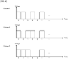
- FIG. 8 is a conceptual diagram illustrating another example of the power pattern outputted from the charging infrastructure, in the same concept as that of FIG. 5 .
- a power pattern signal illustrated in Pattern 1 in FIG. 8 is transmitted to one charging infrastructure 10 out of the plurality of charging infrastructures 10, and a power pattern signal illustrated in Pattern 2 in FIG. 8 is transmitted to another charging infrastructure 10.
- the charging infrastructure 10 corresponding to the vehicle 20 can be specified from the power pattern detected in the vehicle 20.
- connection management unit 210 of the vehicle 20 determines whether or not some power pattern is detected at a time point after a lapse of predetermined time after it becomes in the standby state, at a time point at which the generation of the induced electromotive force in the coil 260 is detected, or at a time point at which some signal is received (step S304).
- connection management unit 210 controls the packet generation / analysis unit 220 to packetize the signal indicating the pairing failure and transmit it to the access point 30 (step S306), and transmits the signal indicating the charging stop to the charging control unit 240.
- the connection management unit 210 controls the packet generation / analysis unit 220 to packetize a signal indicating the detected power pattern as one example of the "third signal" of the present invention and transmit it to the access point 30 (step S305), and transmits the signal indicating the charging start to the charging control unit 240.
- connection management unit 310 of the access point 30 determines whether or not the signal is received at a time point after at a time point after a lapse of predetermined time after it becomes in the standby state, or at a time point at which some signal is received from the vehicle 20 which transmits the signal indicating the pairing start command received in the processing in the step S201 (step S404).
- the connection management unit 310 determines whether or not the pairing is successful (i.e. whether or not there is a signal corresponding to the signal indicating the power pattern transmitted in the processing in the step S305 (refer to FIG. 6 ), among the power pattern signals transmitted in the processing in the step S402 (step S405).
- the connection management unit 310 controls the packet generation / analysis unit 320 to packetize the signal indicating the pairing success and transmit it to the vehicle 20 (step S406), and controls the packet generation / analysis unit 320 to packetize the signal indicating the charging start and transmit it to the charging infrastructure 10 which transmits, in the processing in the step S402, the power pattern signal corresponding to the signal indicating power pattern transmitted in the processing in the step S305.
- the connection management unit 310 controls the packet generation / analysis unit 320 to packetize the signal indicating the pairing failure and transmit it to the vehicle 20 (step S407), and controls the packet generation / analysis unit 320 to packetize the signal indicating the charging stop and transmit it to all the charging infrastructures 10 that transmit the power pattern signals in the processing in the step S402.
- connection management unit 310 the "packet generation / analysis unit 320", and the “packet transmission / reception unit 330" in the second embodiment are one example of the "first charging control apparatus” of the present invention.
- the “connection management unit 310" in the second embodiment is one example of the "distinguishing device” of the "first charging control apparatus” of the present invention.
- the “packet generation / analysis unit 320” and the “packet transmission / reception unit 330" in the second embodiment are one example of the “outputting device” and the "detecting device” of the "first charging control apparatus” of the present invention.
- the "packet generation / analysis unit 220", and the “packet transmission / reception unit 230" and the “coil 260" in the second embodiment are one example of the “second charging control apparatus” of the present invention.
- the “coil 260" in the second embodiment is one example of the "detecting device” of the “second charging control apparatus” of the present invention.
- the "connection management unit 210", the "packet generation / analysis unit 220", and the “packet transmission / reception unit 230" in the second embodiment are one example of the "communicating device” of the "second charging control apparatus” of the present invention.
- the "packet generation / analysis unit 120", the “packet transmission / reception unit 130", the “power transmission control unit 140", the “main circuit 150”, and the “coil 160” in the second embodiment are one example of the "third charging control apparatus” of the present invention.
- the "packet generation / analysis unit 120" and the “packet transmission / reception unit 130” are one example of the “receiving device” of the "third charging control apparatus” of the present invention.
- the “power transmission control unit 140", the “main circuit 150", and the “coil 160” in the second embodiment are one example of the "outputting device” of the "third charging control apparatus” of the present invention.
- the charging system 1 in the embodiments described above the charging system of an electromagnetic induction type is listed.
- the present invention is not limited to the charging system of the electromagnetic induction type, and can be applied to a system which adopts various wireless charging methods, such as, for example, of a radio reception type and of a magnetic field coupling resonance type.
- the "coil 160" and the “coil 260" in the embodiments may be interpreted as "antennas".
- the present invention is not limited to the aforementioned embodiments, but various changes may be made, if desired, without departing from the essence or spirit of the invention which can be read from the claims and the entire specification.
- a charging control apparatus and method, a charging system, a correlation method, and a computer program, which involve such changes, are also intended to be within the technical scope of the present invention.
Priority Applications (1)
| Application Number | Priority Date | Filing Date | Title |
|---|---|---|---|
| EP21211674.3A EP3981640A1 (de) | 2011-02-17 | 2011-02-17 | Ladesteuerungsvorrichtung und -verfahren, ladesystem, korrelationsverfahren und computerprogramm |
Applications Claiming Priority (7)
| Application Number | Priority Date | Filing Date | Title |
|---|---|---|---|
| EP11858953.0A EP2677624B1 (de) | 2011-02-17 | 2011-02-17 | Ladungskontrollvorrichtung und verfahren, ladesystem, zuordnungsverfahren und computerprogramm |
| PCT/JP2011/053378 WO2012111127A1 (ja) | 2011-02-17 | 2011-02-17 | 充電制御装置及び方法、充電システム、対応付け方法、並びにコンピュータプログラム |
| EP21211674.3A EP3981640A1 (de) | 2011-02-17 | 2011-02-17 | Ladesteuerungsvorrichtung und -verfahren, ladesystem, korrelationsverfahren und computerprogramm |
| JP2014137877A JP5820026B2 (ja) | 2011-02-17 | 2014-07-03 | 充電制御装置及び方法、充電システム、対応付け方法、並びにコンピュータプログラム |
| JP2014137856A JP5801454B2 (ja) | 2011-02-17 | 2014-07-03 | 充電制御装置及び方法、充電システム、対応付け方法、並びにコンピュータプログラム |
| JP2014137850A JP5931968B2 (ja) | 2011-02-17 | 2014-07-03 | 充電制御装置及び方法、充電システム、対応付け方法、並びにコンピュータプログラム |
| JP2015152625A JP5987093B2 (ja) | 2011-02-17 | 2015-07-31 | 充電制御装置及び方法、充電システム、対応付け方法、並びにコンピュータプログラム |
Related Parent Applications (2)
| Application Number | Title | Priority Date | Filing Date |
|---|---|---|---|
| EP11858953.0A Division-Into EP2677624B1 (de) | 2011-02-17 | 2011-02-17 | Ladungskontrollvorrichtung und verfahren, ladesystem, zuordnungsverfahren und computerprogramm |
| EP11858953.0A Division EP2677624B1 (de) | 2011-02-17 | 2011-02-17 | Ladungskontrollvorrichtung und verfahren, ladesystem, zuordnungsverfahren und computerprogramm |
Publications (1)
| Publication Number | Publication Date |
|---|---|
| EP3981640A1 true EP3981640A1 (de) | 2022-04-13 |
Family
ID=56234720
Family Applications (2)
| Application Number | Title | Priority Date | Filing Date |
|---|---|---|---|
| EP21211674.3A Pending EP3981640A1 (de) | 2011-02-17 | 2011-02-17 | Ladesteuerungsvorrichtung und -verfahren, ladesystem, korrelationsverfahren und computerprogramm |
| EP11858953.0A Active EP2677624B1 (de) | 2011-02-17 | 2011-02-17 | Ladungskontrollvorrichtung und verfahren, ladesystem, zuordnungsverfahren und computerprogramm |
Family Applications After (1)
| Application Number | Title | Priority Date | Filing Date |
|---|---|---|---|
| EP11858953.0A Active EP2677624B1 (de) | 2011-02-17 | 2011-02-17 | Ladungskontrollvorrichtung und verfahren, ladesystem, zuordnungsverfahren und computerprogramm |
Country Status (4)
| Country | Link |
|---|---|
| US (6) | US9090173B2 (de) |
| EP (2) | EP3981640A1 (de) |
| JP (5) | JP5576511B2 (de) |
| WO (1) | WO2012111127A1 (de) |
Families Citing this family (53)
| Publication number | Priority date | Publication date | Assignee | Title |
|---|---|---|---|---|
| US20160345631A1 (en) | 2005-07-19 | 2016-12-01 | James Monsees | Portable devices for generating an inhalable vapor |
| WO2012111127A1 (ja) * | 2011-02-17 | 2012-08-23 | パイオニア株式会社 | 充電制御装置及び方法、充電システム、対応付け方法、並びにコンピュータプログラム |
| CN104169985A (zh) * | 2012-03-13 | 2014-11-26 | 日立汽车系统株式会社 | 车辆用通信装置以及车辆用通信系统 |
| JP6100014B2 (ja) * | 2013-02-07 | 2017-03-22 | キヤノン株式会社 | 送電装置、送電装置の制御方法及びプログラム |
| US10279934B2 (en) | 2013-03-15 | 2019-05-07 | Juul Labs, Inc. | Fillable vaporizer cartridge and method of filling |
| US10343540B2 (en) | 2013-03-29 | 2019-07-09 | Nissan Motor Co., Ltd. | Non-contact power supply system |
| JP5979308B2 (ja) * | 2013-03-29 | 2016-08-24 | 日産自動車株式会社 | 非接触給電システム |
| JP6130711B2 (ja) * | 2013-04-17 | 2017-05-17 | キヤノン株式会社 | 通信装置、制御方法、及びプログラム |
| JP6213012B2 (ja) * | 2013-07-25 | 2017-10-18 | 株式会社豊田自動織機 | 非接触充電システム、車両及び給電装置 |
| JP5835290B2 (ja) | 2013-08-26 | 2015-12-24 | トヨタ自動車株式会社 | 充電システム及びペアリング方法 |
| JP2015065792A (ja) * | 2013-09-26 | 2015-04-09 | 株式会社豊田自動織機 | 非接触充電システム及び車両 |
| JP2015095939A (ja) * | 2013-11-11 | 2015-05-18 | 株式会社豊田自動織機 | 電力伝送システム及び送電装置 |
| JP2015100173A (ja) * | 2013-11-18 | 2015-05-28 | トヨタ自動車株式会社 | 非接触充電システム及び非接触充電システムのペアリング方法 |
| JP6115453B2 (ja) * | 2013-11-27 | 2017-04-19 | トヨタ自動車株式会社 | 非接触電力伝送システム、および車両 |
| US10159282B2 (en) | 2013-12-23 | 2018-12-25 | Juul Labs, Inc. | Cartridge for use with a vaporizer device |
| USD825102S1 (en) | 2016-07-28 | 2018-08-07 | Juul Labs, Inc. | Vaporizer device with cartridge |
| PL3498115T3 (pl) | 2013-12-23 | 2021-12-20 | Juul Labs International Inc. | Systemy urządzeń do odparowywania |
| US10076139B2 (en) | 2013-12-23 | 2018-09-18 | Juul Labs, Inc. | Vaporizer apparatus |
| US20160366947A1 (en) | 2013-12-23 | 2016-12-22 | James Monsees | Vaporizer apparatus |
| USD842536S1 (en) | 2016-07-28 | 2019-03-05 | Juul Labs, Inc. | Vaporizer cartridge |
| US10058129B2 (en) | 2013-12-23 | 2018-08-28 | Juul Labs, Inc. | Vaporization device systems and methods |
| JP6361132B2 (ja) | 2013-12-24 | 2018-07-25 | トヨタ自動車株式会社 | 非接触電力伝送システム、充電ステーション、および車両 |
| JP5910642B2 (ja) * | 2014-01-22 | 2016-04-27 | トヨタ自動車株式会社 | 非接触充電システム |
| JP2015144529A (ja) | 2014-01-31 | 2015-08-06 | トヨタ自動車株式会社 | 非接触電力伝送システム、および充電ステーション |
| MY161712A (en) | 2014-01-31 | 2017-05-15 | Nissan Motor | Wireless power supply system and power transmission device |
| JP5937631B2 (ja) | 2014-01-31 | 2016-06-22 | トヨタ自動車株式会社 | 非接触電力伝送システムおよび充電ステーション |
| JP5962687B2 (ja) * | 2014-01-31 | 2016-08-03 | トヨタ自動車株式会社 | 非接触電力伝送システム、および充電ステーション |
| JP2015159693A (ja) * | 2014-02-25 | 2015-09-03 | 株式会社豊田自動織機 | 非接触電力伝送システム及び受電装置 |
| WO2015155838A1 (ja) * | 2014-04-08 | 2015-10-15 | 日産自動車株式会社 | 非接触給電システム及び非接触受電装置 |
| CN106165245B (zh) * | 2014-04-08 | 2017-10-03 | 日产自动车株式会社 | 非接触供电系统以及非接触受电装置 |
| JP6359924B2 (ja) * | 2014-09-17 | 2018-07-18 | トヨタ自動車株式会社 | 非接触送受電システム |
| CN112155255A (zh) | 2014-12-05 | 2021-01-01 | 尤尔实验室有限公司 | 校正剂量控制 |
| KR102329582B1 (ko) * | 2015-03-24 | 2021-11-23 | 지이 하이브리드 테크놀로지스, 엘엘씨 | 무선 전력 전송 및 충전 시스템 |
| CN104816646B (zh) * | 2015-04-02 | 2017-06-06 | 西安交通大学 | 一种用于移动‑静止兼容式电动汽车的无线电能传输系统 |
| JP6487883B2 (ja) * | 2015-08-26 | 2019-03-20 | 大同股▲ふん▼有限公司 | 障害回復方法、およびそれを用いたモノのインターネットシステムおよび充電システム |
| CN106608265A (zh) * | 2015-10-16 | 2017-05-03 | 张鹏 | 轨道式移动机器人 |
| JP6459998B2 (ja) * | 2016-02-04 | 2019-01-30 | トヨタ自動車株式会社 | 非接触送電システム |
| DE202017007467U1 (de) | 2016-02-11 | 2021-12-08 | Juul Labs, Inc. | Befüllbare Verdampferkartusche |
| MX2018009703A (es) | 2016-02-11 | 2019-07-08 | Juul Labs Inc | Cartuchos de fijacion segura para dispositivos vaporizadores. |
| US10405582B2 (en) | 2016-03-10 | 2019-09-10 | Pax Labs, Inc. | Vaporization device with lip sensing |
| JP6160742B2 (ja) * | 2016-05-18 | 2017-07-12 | トヨタ自動車株式会社 | 非接触電力伝送システム |
| USD849996S1 (en) | 2016-06-16 | 2019-05-28 | Pax Labs, Inc. | Vaporizer cartridge |
| USD851830S1 (en) | 2016-06-23 | 2019-06-18 | Pax Labs, Inc. | Combined vaporizer tamp and pick tool |
| USD836541S1 (en) | 2016-06-23 | 2018-12-25 | Pax Labs, Inc. | Charging device |
| WO2018061857A1 (ja) * | 2016-09-30 | 2018-04-05 | 日本電気株式会社 | 充電システム、充電コントローラ、充電器、情報装置、充電方法および記録媒体 |
| USD887632S1 (en) | 2017-09-14 | 2020-06-16 | Pax Labs, Inc. | Vaporizer cartridge |
| KR101857407B1 (ko) * | 2018-01-30 | 2018-06-20 | (주)에프티글로벌 | 차량 위치파악이 가능한 자동경로차량용 무선전력전송 시스템 및 자동경로차량 위치파악방법 |
| JP6992732B2 (ja) * | 2018-11-15 | 2022-01-13 | トヨタ自動車株式会社 | 非接触送受電システム |
| CN109878351A (zh) * | 2019-03-13 | 2019-06-14 | 章强 | 一种新能源汽车行驶中进行交互式无线充电的方法 |
| CN114206662A (zh) * | 2019-08-05 | 2022-03-18 | 现代自动车株式会社 | 电力传输中的配对控制方法和装置 |
| WO2021127619A1 (en) * | 2019-12-20 | 2021-06-24 | Witricity Corporation | Wireless network pairing for wireless electric vehicle charging |
| CN113135105A (zh) * | 2021-05-25 | 2021-07-20 | 国网北京市电力公司 | 充电装置、其控制方法、控制装置以及充电系统 |
| JP2023000399A (ja) * | 2021-06-17 | 2023-01-04 | トヨタ自動車株式会社 | 車両、給電方法及び通信装置 |
Citations (5)
| Publication number | Priority date | Publication date | Assignee | Title |
|---|---|---|---|---|
| JP2006074868A (ja) | 2004-08-31 | 2006-03-16 | Fuji Heavy Ind Ltd | 電気自動車のバッテリ充電システム |
| WO2010030005A1 (ja) * | 2008-09-11 | 2010-03-18 | 矢崎総業株式会社 | 車両用ワイヤレス充電システム |
| US20100145568A1 (en) * | 2008-12-10 | 2010-06-10 | Yazaki Corporation | Charge monitoring apparatus |
| EP2199143A1 (de) * | 2008-12-22 | 2010-06-23 | General Electric Company | System und Verfahren zur Aufladung eines Elektrofahrzeugs und Abrechnung unter Verwendung eines drahtlosen Fahrzeugkommunikationsdienstes |
| JP2010178450A (ja) | 2009-01-28 | 2010-08-12 | Chugoku Electric Power Co Inc:The | 電気自動車の充電システム |
Family Cites Families (12)
| Publication number | Priority date | Publication date | Assignee | Title |
|---|---|---|---|---|
| EP0788211B1 (de) * | 1996-01-30 | 2002-08-28 | Sumitomo Wiring Systems, Ltd. | Verbindungssystem mit zugehörigem Verfahren |
| JP2001177916A (ja) | 1999-12-10 | 2001-06-29 | Toyota Motor Corp | エネルギー供給装置 |
| JP4366385B2 (ja) * | 2006-08-31 | 2009-11-18 | 株式会社東海理化電機製作所 | 充電システム |
| JP4725612B2 (ja) | 2008-07-16 | 2011-07-13 | セイコーエプソン株式会社 | 送電制御装置、送電装置、受電制御装置、受電装置及び電子機器 |
| JP2010104097A (ja) | 2008-10-21 | 2010-05-06 | Seiko Epson Corp | 認証処理装置、送電装置、受電装置、及び電子機器 |
| JP4815485B2 (ja) * | 2008-11-14 | 2011-11-16 | 東光株式会社 | 非接触電力伝送装置 |
| EP2199141B1 (de) | 2008-12-22 | 2016-06-15 | Aisin Aw Co., Ltd. | Fahrzeugführungsvorrichtung zum Laden der Fahrzeugbatterie |
| JP5379495B2 (ja) | 2009-01-09 | 2013-12-25 | 株式会社アルファ | 電気自動車の充電ステーション |
| WO2010098412A1 (ja) * | 2009-02-25 | 2010-09-02 | マスプロ電工株式会社 | 移動体の電力供給システム |
| US20110302078A1 (en) * | 2010-06-02 | 2011-12-08 | Bryan Marc Failing | Managing an energy transfer between a vehicle and an energy transfer system |
| DE112010006090B4 (de) | 2010-12-24 | 2021-10-21 | Toyota Jidosha Kabushiki Kaisha | System für kontaktloses Laden, Verfahren für kontaktloses Laden, Fahrzeug zum kontaktlosen Laden und Verwaltungsvorrichtung für kontaktloses Laden |
| WO2012111127A1 (ja) * | 2011-02-17 | 2012-08-23 | パイオニア株式会社 | 充電制御装置及び方法、充電システム、対応付け方法、並びにコンピュータプログラム |
-
2011
- 2011-02-17 WO PCT/JP2011/053378 patent/WO2012111127A1/ja active Application Filing
- 2011-02-17 EP EP21211674.3A patent/EP3981640A1/de active Pending
- 2011-02-17 JP JP2012557729A patent/JP5576511B2/ja active Active
- 2011-02-17 EP EP11858953.0A patent/EP2677624B1/de active Active
- 2011-02-17 US US13/985,099 patent/US9090173B2/en active Active
-
2014
- 2014-07-03 JP JP2014137856A patent/JP5801454B2/ja active Active
- 2014-07-03 JP JP2014137850A patent/JP5931968B2/ja active Active
- 2014-07-03 JP JP2014137877A patent/JP5820026B2/ja active Active
- 2014-08-29 US US14/472,412 patent/US9221352B2/en active Active
- 2014-09-05 US US14/477,897 patent/US9162584B2/en active Active
- 2014-09-05 US US14/477,894 patent/US9272632B2/en active Active
-
2015
- 2015-07-31 JP JP2015152625A patent/JP5987093B2/ja active Active
- 2015-08-11 US US14/823,242 patent/US9221353B2/en active Active
- 2015-12-14 US US14/967,849 patent/US9592741B2/en active Active
Patent Citations (5)
| Publication number | Priority date | Publication date | Assignee | Title |
|---|---|---|---|---|
| JP2006074868A (ja) | 2004-08-31 | 2006-03-16 | Fuji Heavy Ind Ltd | 電気自動車のバッテリ充電システム |
| WO2010030005A1 (ja) * | 2008-09-11 | 2010-03-18 | 矢崎総業株式会社 | 車両用ワイヤレス充電システム |
| US20100145568A1 (en) * | 2008-12-10 | 2010-06-10 | Yazaki Corporation | Charge monitoring apparatus |
| EP2199143A1 (de) * | 2008-12-22 | 2010-06-23 | General Electric Company | System und Verfahren zur Aufladung eines Elektrofahrzeugs und Abrechnung unter Verwendung eines drahtlosen Fahrzeugkommunikationsdienstes |
| JP2010178450A (ja) | 2009-01-28 | 2010-08-12 | Chugoku Electric Power Co Inc:The | 電気自動車の充電システム |
Also Published As
| Publication number | Publication date |
|---|---|
| US20140375267A1 (en) | 2014-12-25 |
| US9221352B2 (en) | 2015-12-29 |
| US20160096436A1 (en) | 2016-04-07 |
| EP2677624B1 (de) | 2022-01-05 |
| US9221353B2 (en) | 2015-12-29 |
| US20150343917A1 (en) | 2015-12-03 |
| JP2014195405A (ja) | 2014-10-09 |
| US9090173B2 (en) | 2015-07-28 |
| JP2015195724A (ja) | 2015-11-05 |
| JP2014195406A (ja) | 2014-10-09 |
| EP2677624A1 (de) | 2013-12-25 |
| JP5801454B2 (ja) | 2015-10-28 |
| US9272632B2 (en) | 2016-03-01 |
| US9162584B2 (en) | 2015-10-20 |
| EP2677624A4 (de) | 2015-12-23 |
| WO2012111127A1 (ja) | 2012-08-23 |
| US20140035522A1 (en) | 2014-02-06 |
| JP5931968B2 (ja) | 2016-06-08 |
| JP2014212696A (ja) | 2014-11-13 |
| US9592741B2 (en) | 2017-03-14 |
| JP5987093B2 (ja) | 2016-09-06 |
| JP5820026B2 (ja) | 2015-11-24 |
| JP5576511B2 (ja) | 2014-08-20 |
| US20140375266A1 (en) | 2014-12-25 |
| US20140368166A1 (en) | 2014-12-18 |
| JPWO2012111127A1 (ja) | 2014-07-03 |
Similar Documents
| Publication | Publication Date | Title |
|---|---|---|
| US9592741B2 (en) | Charging control apparatus, charging control method, and computer program implementing such | |
| US10300805B2 (en) | Systems, methods, and apparatus related to mutual detection and identification of electric vehicle and charging station | |
| CN107554318B (zh) | 缆上控制盒、电动车辆充电方法及供应设备通信控制器 | |
| EP2870022B1 (de) | Systeme, verfahren und vorrichtung im zusammenhang mit dem parken und drahtloses laden von elektrofahrzeugen | |
| CN106853778B (zh) | 用于发现evse的pd的方法和装置以及secc的操作方法 | |
| CN105429251A (zh) | 电动车辆充电装置 | |
| JP5853209B2 (ja) | 電力線通信システム及び車両 | |
| KR20180029462A (ko) | 전기자동차의 충전 제어 방법 및 장치 | |
| JP6201021B2 (ja) | 充電制御装置及び方法、充電システム、対応付け方法、並びにコンピュータプログラム | |
| JP2014063090A (ja) | 停電エリア特定装置、停電エリア特定方法及び停電エリア特定システム | |
| WO2017121748A1 (en) | Monitoring of electric vehicle supply equipment | |
| CN101989720A (zh) | 为电动汽车充电的充电插座 | |
| KR20170025015A (ko) | 차량용 무선 충전 장치 및 제어 방법 | |
| JP2016101006A (ja) | 電気自動車判別方法及び電気自動車判別システム | |
| JP5743159B2 (ja) | 充電器の利用者認証切り替え方法および充電器並びに電気自動車充電サービスコントローラ |
Legal Events
| Date | Code | Title | Description |
|---|---|---|---|
| PUAI | Public reference made under article 153(3) epc to a published international application that has entered the european phase |
Free format text: ORIGINAL CODE: 0009012 |
|
| STAA | Information on the status of an ep patent application or granted ep patent |
Free format text: STATUS: THE APPLICATION HAS BEEN PUBLISHED |
|
| AC | Divisional application: reference to earlier application |
Ref document number: 2677624 Country of ref document: EP Kind code of ref document: P |
|
| AK | Designated contracting states |
Kind code of ref document: A1 Designated state(s): AL AT BE BG CH CY CZ DE DK EE ES FI FR GB GR HR HU IE IS IT LI LT LU LV MC MK MT NL NO PL PT RO RS SE SI SK SM TR |
|
| RAP1 | Party data changed (applicant data changed or rights of an application transferred) |
Owner name: TOYOTA JIDOSHA KABUSHIKI KAISHA |
|
| STAA | Information on the status of an ep patent application or granted ep patent |
Free format text: STATUS: REQUEST FOR EXAMINATION WAS MADE |
|
| 17P | Request for examination filed |
Effective date: 20221012 |
|
| RBV | Designated contracting states (corrected) |
Designated state(s): AL AT BE BG CH CY CZ DE DK EE ES FI FR GB GR HR HU IE IS IT LI LT LU LV MC MK MT NL NO PL PT RO RS SE SI SK SM TR |