EP0782508B1 - Schleifstück für stromabnehmer und verfahren zu seiner herstellung - Google Patents
Schleifstück für stromabnehmer und verfahren zu seiner herstellung Download PDFInfo
- Publication number
- EP0782508B1 EP0782508B1 EP96927064A EP96927064A EP0782508B1 EP 0782508 B1 EP0782508 B1 EP 0782508B1 EP 96927064 A EP96927064 A EP 96927064A EP 96927064 A EP96927064 A EP 96927064A EP 0782508 B1 EP0782508 B1 EP 0782508B1
- Authority
- EP
- European Patent Office
- Prior art keywords
- cavity
- preform
- carbon strip
- support
- strip
- Prior art date
- Legal status (The legal status is an assumption and is not a legal conclusion. Google has not performed a legal analysis and makes no representation as to the accuracy of the status listed.)
- Expired - Lifetime
Links
- 238000004519 manufacturing process Methods 0.000 title description 14
- OKTJSMMVPCPJKN-UHFFFAOYSA-N Carbon Chemical compound [C] OKTJSMMVPCPJKN-UHFFFAOYSA-N 0.000 claims abstract description 51
- 229910052799 carbon Inorganic materials 0.000 claims abstract description 51
- 238000000034 method Methods 0.000 claims description 22
- 239000004033 plastic Substances 0.000 claims description 10
- 229920003023 plastic Polymers 0.000 claims description 10
- 229920002430 Fibre-reinforced plastic Polymers 0.000 claims description 4
- 239000011151 fibre-reinforced plastic Substances 0.000 claims description 4
- 238000010438 heat treatment Methods 0.000 claims description 3
- 239000004604 Blowing Agent Substances 0.000 claims description 2
- 239000000203 mixture Substances 0.000 claims description 2
- XLYOFNOQVPJJNP-UHFFFAOYSA-N water Substances O XLYOFNOQVPJJNP-UHFFFAOYSA-N 0.000 claims description 2
- 239000000463 material Substances 0.000 claims 5
- 239000010410 layer Substances 0.000 claims 2
- 239000002245 particle Substances 0.000 claims 2
- 239000002344 surface layer Substances 0.000 claims 2
- 229910000838 Al alloy Inorganic materials 0.000 claims 1
- LFQSCWFLJHTTHZ-UHFFFAOYSA-N Ethanol Chemical compound CCO LFQSCWFLJHTTHZ-UHFFFAOYSA-N 0.000 claims 1
- 238000005187 foaming Methods 0.000 claims 1
- 239000007788 liquid Substances 0.000 claims 1
- 239000011796 hollow space material Substances 0.000 abstract 6
- 239000003245 coal Substances 0.000 description 39
- 229910052751 metal Inorganic materials 0.000 description 11
- 239000002184 metal Substances 0.000 description 11
- 229910052782 aluminium Inorganic materials 0.000 description 4
- XAGFODPZIPBFFR-UHFFFAOYSA-N aluminium Chemical compound [Al] XAGFODPZIPBFFR-UHFFFAOYSA-N 0.000 description 4
- 239000003575 carbonaceous material Substances 0.000 description 4
- 239000004020 conductor Substances 0.000 description 4
- 238000000465 moulding Methods 0.000 description 4
- 239000000853 adhesive Substances 0.000 description 3
- 230000001070 adhesive effect Effects 0.000 description 3
- 230000008901 benefit Effects 0.000 description 3
- 230000015572 biosynthetic process Effects 0.000 description 3
- 238000001125 extrusion Methods 0.000 description 3
- 239000007789 gas Substances 0.000 description 3
- 239000012811 non-conductive material Substances 0.000 description 3
- 238000005476 soldering Methods 0.000 description 3
- 230000005540 biological transmission Effects 0.000 description 2
- 239000000969 carrier Substances 0.000 description 2
- 150000001875 compounds Chemical class 0.000 description 2
- 238000009826 distribution Methods 0.000 description 2
- 238000005516 engineering process Methods 0.000 description 2
- 230000007704 transition Effects 0.000 description 2
- 238000004026 adhesive bonding Methods 0.000 description 1
- 238000007664 blowing Methods 0.000 description 1
- 239000003610 charcoal Substances 0.000 description 1
- 230000001419 dependent effect Effects 0.000 description 1
- 238000001514 detection method Methods 0.000 description 1
- 239000000428 dust Substances 0.000 description 1
- 230000000694 effects Effects 0.000 description 1
- 230000007613 environmental effect Effects 0.000 description 1
- 239000000835 fiber Substances 0.000 description 1
- 239000006260 foam Substances 0.000 description 1
- 238000011065 in-situ storage Methods 0.000 description 1
- 230000036316 preload Effects 0.000 description 1
- 150000003839 salts Chemical class 0.000 description 1
- 238000007493 shaping process Methods 0.000 description 1
- 239000007787 solid Substances 0.000 description 1
- 239000007921 spray Substances 0.000 description 1
- 229920003002 synthetic resin Polymers 0.000 description 1
- 239000000057 synthetic resin Substances 0.000 description 1
Images


Classifications
-
- B—PERFORMING OPERATIONS; TRANSPORTING
- B60—VEHICLES IN GENERAL
- B60L—PROPULSION OF ELECTRICALLY-PROPELLED VEHICLES; SUPPLYING ELECTRIC POWER FOR AUXILIARY EQUIPMENT OF ELECTRICALLY-PROPELLED VEHICLES; ELECTRODYNAMIC BRAKE SYSTEMS FOR VEHICLES IN GENERAL; MAGNETIC SUSPENSION OR LEVITATION FOR VEHICLES; MONITORING OPERATING VARIABLES OF ELECTRICALLY-PROPELLED VEHICLES; ELECTRIC SAFETY DEVICES FOR ELECTRICALLY-PROPELLED VEHICLES
- B60L5/00—Current collectors for power supply lines of electrically-propelled vehicles
- B60L5/18—Current collectors for power supply lines of electrically-propelled vehicles using bow-type collectors in contact with trolley wire
- B60L5/20—Details of contact bow
- B60L5/205—Details of contact bow with carbon contact members
-
- B—PERFORMING OPERATIONS; TRANSPORTING
- B60—VEHICLES IN GENERAL
- B60L—PROPULSION OF ELECTRICALLY-PROPELLED VEHICLES; SUPPLYING ELECTRIC POWER FOR AUXILIARY EQUIPMENT OF ELECTRICALLY-PROPELLED VEHICLES; ELECTRODYNAMIC BRAKE SYSTEMS FOR VEHICLES IN GENERAL; MAGNETIC SUSPENSION OR LEVITATION FOR VEHICLES; MONITORING OPERATING VARIABLES OF ELECTRICALLY-PROPELLED VEHICLES; ELECTRIC SAFETY DEVICES FOR ELECTRICALLY-PROPELLED VEHICLES
- B60L2200/00—Type of vehicles
- B60L2200/26—Rail vehicles
Definitions
- the invention relates to a contact strip for pantographs with an elongated carrier and an elongated one Carbon strip, which is supported by the carrier, and a Method of making the contact strip.
- Such conventional contact strips have been manufactured and operating various disadvantages. There is a disadvantage in that between the contact wire on which the contact strip slides along, and the exposed surfaces of the metal support arcing can occur. This Arcing can occur especially through the formation of moisture and especially can be brought about by ice or hoarfrost formation. With such an arc, the contact strip, in particular the metal support. Another The disadvantage is the different thermal expansion properties the coal bar and the support. This can happen with Temperature fluctuations to different extents of this guide both elements, creating the entire contact strip can bend like a bimetal. This can to mechanical damage, especially in the area of Carbon strip, as well as thermal overload of the adhesive joint between the carbon strip and the carrier. After all, that is Production of the conventional contact strips is complex because especially the manufacture of a safe, durable and heavy-duty connection between the coal bar and the separately manufactured by them a considerable effort requirement.
- From DE-PS 431 365, DE-PS 671 946, AT-PS 139 525 and AT-PS 140 894 are contact strips with internal carrier known, the composed of lined sections Coal strips tubular one continuous Enclose cavity in which the carbon strip is supported Metal carrier is arranged.
- the metal support is tubular, and its power transmission connection with the Coal ledge can be done either by the metal support is slotted and with elastic preload lies against the inner wall of the carbon strip (AT-PS 139 525), or that between the metal support and the carbon strip a pouring compound is arranged (AT-PS 140 894), if the coal bar or its sections are not rotatable the carrier are stored (DE-PS 431 365 and DE-PS 506 064).
- the carbon material of the carbon strip has very limited tensile stresses can accommodate the arrangement of an elastic prestressed beam in the cavity of the coal strip problematic.
- the introduction of a pouring compound between Carrier and carbon strip does not lead to an optimal power transmission and live connection.
- the object of the invention is a rational with modern To specify manufacturing methods of the contact strip that can be produced, that meets today's requirements for mechanical and electrical Resilience is enough and a secure connection between the coal bar and that arranged in its cavity Carrier can be achieved.
- the method according to the invention sees a direct in-situ molding of the carrier to the inner wall of the cavity Coal bar before. This will ensure a uniform and force-transmitting system of the carrier on the inner wall of the cavity of the coal ledge, which also at the production of the carbon strip inevitable tolerances the cross-sectional dimensions of the cavity compensated for themselves become.
- the coal is in the finished contact strip not subjected to permanent tensile stresses by the wearer. Since the carbon strip the carrier to at least three Encloses sides, there is especially on the long sides of the contact strip no exposed surfaces of the carrier, where an arc from the carrier to the contact wire could skip. Different thermal expansion can also occur the coal bar and the carrier do not become one Curvature of the contact strip cause the carbon strip Carrier essentially surrounds on all sides.
- Fig. 1 to 4 cross sections through different embodiments of manufactured with the inventive method Contact strips.
- the slider shown in cross section in Fig. 1 is made from a carbon strip 1 and a carrier 3.
- This Coal bar 1 consists of a usual for pantographs Carbon material and is by an extrusion or extrusion process made with a cross section that a completely encloses in the longitudinal direction continuous cavity.
- the cross section of the carbon strip 1 can therefore be called tubular.
- the one from the coal bar 1 enclosed cavity is in the embodiment of FIG. 1 rectangular, but can of course have other shapes exhibit.
- the carrier 3 is in the one enclosed by the carbon strip 1 Cavity arranged. It consists of the embodiment a rectangular hollow profile and can be made of conductive and non-conductive material. Further, in the embodiment 1 in the cavity in the coal bar 1 on the top of the carrier 3 is a longitudinal one arranged electrically conductive layer 5. Especially it is advantageous if the conductive layer 5 consists of a is made of braided metal wire, as shown in Fig. 1 indicated. However, the electrically conductive layer 5 can also e.g. from a galvanically applied covering on the Top of the carrier 3 and / or on the inside of the Cavity of the coal strip 1 exist.
- the carrier 3 can be made of electrically conductive or non-conductive Material. If the carrier 3 out non-conductive material, such as fiber reinforced Plastic is an electrically conductive layer 5 particularly advantageous to the electrical current from the carbon strip 1 removed from the contact wire (not shown) is, in the longitudinal direction of the coal bar 1 to provided at the ends of the contact piece conduct. If the carrier 3 made of electrically conductive material exists, e.g. made of foamed aluminum, it is electric Conductive layer 5 may not be absolutely necessary but still be advantageous to the power transition to improve the carbon strip 1 in the carrier 3.
- a tubular preform e.g. made of fiber reinforced, not yet hardened plastic (a so-called "Prepreg") manufactured, the smaller cross-sectional dimensions than the cavity in the coal bar 1 having.
- a pressure medium e.g. Compressed air or an alcohol-water mixture
- an internal pressure applied to the preform and this thereby expanded so that it is against the inner wall of the cavity is pressed and molded.
- you leave harden the plastic so that you can completely one Contour of the cavity and adapted with its inner wall receives positively and non-positively connected carrier.
- the for Curing required temperature of e.g. B. over 150 ° one by heating the pressure medium and / or heating the Apply carbon strip 1 from the outside.
- the carrier also e.g. made of aluminum foam using the described method or by using the blowing effect of a blowing agent, with direct molding against the inner wall of the cavity produce.
- this is serving as a current conductor metal wire mesh 5 or the like.
- the plastic also in the spaces between the Metal mesh 5 penetrate so that it is embedded becomes.
- a particular advantage of the contact strip according to the invention consists in that the 3 surrounding the carrier Charcoal bar 1 can give any external shape.
- the carbon strip 1 an outer cross-sectional contour that exactly matches the outline of currently commercially available, from an aluminum carrier with on it glued carbon strip corresponds to existing contact strips, more precisely the outer contour of the one from the Germans Bundesbahn used standard slider.
- the coal strip 1 by designing the extrusion nozzle accordingly, any desired e.g. aerodynamically advantageous outer contour give.
- the contact strip according to the invention Another major benefit that comes from being free selectable cross-sectional shape of carbon strip and carrier results in the contact strip according to the invention consists in that also in terms of weight and mass distribution of the contact strip has extensive design freedom consists. Compared to the commercially available contact strips, all in adhesive, soldering or clamping technology can be produced, the contact strip according to the invention either manufactured with exactly the same weight, to optimally match existing pantograph systems, or with a significant, e.g. by 30% or more less Weight, resulting in significant improvements in the Achieve dynamic behavior of the pantograph system to let.
- Another particular advantage is that the carrier and its electrical contact with the coal bar, there it is surrounded on all sides by carbon material, much more resistant and less sensitive to environmental influences, such as corrosive gases, aggressive dust, salt spray etc. is considered the contact strips used today with exposed metal or plastic carriers.
- the Carbon strip 1 encloses the Carbon strip 1 a longitudinal cavity, seen in cross section a wide lower part and has an approximately circular upper part.
- Carrier 3 which is designed in a similar manner as this was described in the embodiment of FIG. 1.
- in the upper circular part of the cavity is a in the longitudinal direction continuous wire coil 7, which is preloaded bears against the inner wall of the coal strip 1 and serves as an electrical conductor to the removed from the contact wire electric current in the longitudinal direction of the Derive coal strip 1.
- the wire coil 7 is in one longitudinally stretched state in the cavity pulled in and then relaxed by letting go, so that it rests against the inner wall due to its elastic restoring force the coal bar 1 creates.
- the upper, circular one Part of the cavity also used as a breakage detector channel become.
- he is at the end of the coal bar 1 connected to a facility that constantly a predetermined Maintains gas pressure in the cavity.
- a crack in the Carbon strip 1, or wear going to the cavity causes a drop in gas pressure that detects and as signs of damage or Wear of the coal bar 1 can serve.
- Appropriate Fracture detection devices are known to the person skilled in the art.
- the cross section of the coal strip according to FIG. 3 is thus C-shaped.
- a carrier 3 'introduced as a solid in cross-section T-shaped Bar is formed in the cavity of the coal strip 1 .
- the carrier 3 ' can e.g. out foamed plastic or aluminum.
- an electrically conductive Layer 5 which the current drawn from the contact wire from the Carbon bar 1 forwards. If the carrier 3 is itself conductive, so the layer 5 can be omitted.
- the embodiment according to FIG. 4 represents a carbon strip 1 with a C-shaped cross section as in Fig. 3
- Carrier 3 " is made in the same manner as in the embodiment 1 was introduced.
- the carrier 3 " is made, for example, from a tubular preform fiber-reinforced plastic in the cavity of the carbon strip 1 introduced, expanded by means of compressed air and on the inner wall of the cavity including the side walls of the gap open towards the bottom, so that after hardening of the synthetic resin, a T-shaped carrier 3 ", which completely closes the downward-opening cavity, arises.
- the carrier 3 " can in the same way as already shown under Fig. 1 with a contact device to derive the current from the coal strip 1 to the Be provided ends of the contact strip.
- Fig. 5 shows in longitudinal section a possible embodiment of the in one of its ends shown in Fig. 1.
- the lower wall of both the coal strip 1 and the Carrier 3 is provided with a longitudinal slot 11.
- This slot 11 extends fastening bolts 13, whose heads 15 are inside the carrier 3 and there e.g. can be attached in a suitable manner.
- Fig. 6 shows a further possible embodiment in longitudinal section of the contact strip shown in Fig. 1 at its end.
- the lower wall, both the coal bar 1 and the Carrier 3 is provided with at least one bore 16.
- Fastening bolts 18 extend through this bore, the slide nuts 19 located in the interior of the carrier are screwed.
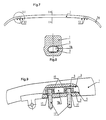
- Fig. 7 shows a side view of an inventive Contact strip 1, on which curved in the area of its ends Horns 1a, so-called casserole horns for the contact wire, in one piece are molded.
- Fig. 8 shows a cross section along the line II - II of Fig. 7 Then surrounds the carbon strip 1 on all sides longitudinally continuous cavity 1b, which has an oval, cross section slightly angled at the top having.
- the tubular support 3 In the cavity 1b is the tubular support 3, by the described deformation process directly to the inner wall of the cavity 1b is integrally formed, between the carrier 3 and the inner wall of the cavity 1b, a thin conductive layer 5, e.g. B. wire mesh is arranged, the carrier 3 on all sides surrounds.
- the cavity 1b and the carrier 3 arranged therein extend along the entire length of the contact strip Figure 7 including the horns 1a, so that the Horns la are supported by the carrier 3.
- the one for manufacturing of the carrier 3 serving tubular preform becomes sufficiently softened or flexible State inserted into the cavity 1b so that it is the can adapt to the curved shape of the horns 1a.
- Fig. 9 shows a detail at III in Fig. 7 at the transition between the middle part and the horn 1a of the contact strip.
- Through holes 11 in the lower wall of the coal strip 1 are fastening bolts 13 inserted and inside the carrier 3 by nuts 15 secured.
- the bolts 13 are used for mechanical Attachment of the contact strip to a pantograph bracket.
- a metallic contact element is used for electrical contacting, that in the illustrated embodiment is in contact with the outer surface of the carbon strip 1.
- the metallic contact element is also possible through an opening in the lower wall of the coal strip 1 through with the conductive layer 5 between carrier 3 and to bring coal bar 1 into contact.
- the described manufacturing process with direct molding an internal carrier to the cavity of the Coal ledge allows one compared to the conventional one Processes with soldering, adhesive or clamping technology are very cost-effective Manufacturing of the contact strip in practically one Operation without substantial rework on the contact strip.
- the beam formation, the mechanical connection of the beam and carbon strip and the electrical contacting of carriers and coal bar are realized in one operation.
- the process delivers a real integral grinder that in particular also directly molded on horns in one piece Can have shape, resulting in optimal strength and high operational reliability, since no additional Connection between carbon strip, casserole horns and carrier is required.
Landscapes
- Engineering & Computer Science (AREA)
- Power Engineering (AREA)
- Transportation (AREA)
- Mechanical Engineering (AREA)
- Current-Collector Devices For Electrically Propelled Vehicles (AREA)
- Motor Or Generator Current Collectors (AREA)
- Polishing Bodies And Polishing Tools (AREA)
- Electrical Discharge Machining, Electrochemical Machining, And Combined Machining (AREA)
Description
Claims (15)
- Schleifstück für Stromabnehmer bestehend aus einer langgestreckten Kohleleiste (1) mit rohrförmigem, U-förmigem oder C-förmigem Querschnitt, die einen in Längsrichtung der Kohleleiste verlaufenden Hohlraum an mindestens drei Seiten umschließt, und einem in dem Hohlraum angeordneten langgestreckten Träger (3), der die Kohleleiste (1) abstützt, dadurch gekennzeichnet, daß der Träger (3) ein Formstück ist, das seine Endform durch unmittelbares Anformen an die Innenwandung des Hohlraums der Kohleleiste (1) erhalten hat.
- Schleifstück nach Anspruch 1, dadurch gekennzeichnet, daß der Träger (3) aus Kunststoff geformt ist, und daß zwischen dem Träger (3) und mindestens einem Teil der Innenwandung des Hohlraums der Kohleleiste (1) ein stromleitendes Element oder eine stromleitende Schicht (5, 9) angeordnet ist.
- Schleifstück nach Anspruch 1, dadurch gekennzeichnet, daß der Träger (3) aus Kunststoff geformt ist, und daß mindestens die an die Innenwandung des Hohlraums der Kohleleiste (1) angrenzende Oberflächenschicht des Trägers (3) durch Einlagerung elektrisch leitfähiger Fasern, Partikel oder dergleichen elektrisch leitfähig gemacht ist.
- Schleifstück nach einem der Ansprüche 1 bis 3, dadurch gekennzeichnet, daß die Kohleleiste (1) mindestens in einem ihrer Endbereiche mindestens eine Öffnung in Form eines längsverlaufenden Schlitzes, einer Bohrung oder dergleichen aufweist, durch die ein elektrisches Kontaktelement und/oder ein mechanisches Befestigungsmittel mit dem Träger verbunden ist.
- Schleifstück nach einem der Ansprüche 1 bis 4, dadurch gekennzeichnet, daß an der Kohleleiste in ihren Endbereichen gekrümmte Hörner (1a) einstückig angeformt sind, daß sich der Hohlraum der Kohleleiste auch durch die Hörner (1a) erstreckt und daß sich der Träger (3) mit einer entsprechend den Hörnern (1a) gekrümmten Form auch über die Länge der Hörner (1a) erstreckt und diese abstützt.
- Verfahren zur Herstellung eines Schleifstücks für Stromabnehmer, bestehend aus einer langgestreckten Kohleleiste (1) mit rohrförmigem, U-förmigem oder C-förmigem Querschnitt, die einen in Längsrichtung der Kohleleiste verlaufenden Hohlraum an mindestens drei Seiten umschließt, und einem in dem Hohlraum angeordneten langgestreckten Träger (3), der die Kohleleiste (1) abstützt, mit den Schritten Herstellen eines Vorformlings des Trägers, dessen Querschnittsabmessungen kleiner als die des Hohlraums der Kohleleiste sind,Einbringen des Vorformlings in den Hohlraum der Kohleleiste,Verformen des Vorformlings zum fertigen Träger durch ein Formungsverfahren, durch welches der Vorformling im Querschnitt aufgeweitet und gegen mindestens einen Teil der Innenwandung des Hohlraums angeformt wird.
- Verfahren nach Anspruch 6, bei dem eine elektrisch leitfähige Schicht (5) zwischen dem Vorformling und mindestens einem Teil der Innenwandung des Hohlraums angeordnet wird.
- Verfahren nach Anspruch 6 oder 7, bei dem der Vorformling rohrförmig ist und durch Zuführen eines Druckmediums in das Innere des Vorformlings verformt und aufgeweitet wird.
- Verfahren nach einem der Ansprüche 6 bis 8, bei dem der Vorformling aus nicht ausgehärtetem Kunststoff besteht und während oder nach seiner Verformung ausgehärtet wird.
- Verfahren nach Anspruch 8, dadurch gekennzeichnet, daß ein erhitztes Druckmedium verwendet wird, welches die für die Aushärtung erforderliche Erwärmung des Vorformlings bewirkt oder unterstützt.
- Verfahren nach Anspruch 8 oder 10, dadurch gekennzeichnet, daß als Druckmedium eine Flüssigkeit, insbesondere ein Gemisch aus Wasser und Alkohol, benutzt wird.
- Verfahren nach Anspruch 9, bei dem der Kunststoff ein faserverstärkter Kunststoff ist.
- Verfahren nach einem der Ansprüche 6 bis 8, bei dem der Vorformling aus einer mittels Treibmittel aufschäumbaren Aluminiumlegierung besteht und durch Aufschäumen verformt wird.
- Verfahren nach Anspruch 9 oder 12, dadurch gekennzeichnet, daß der Vorformling mindestens in seiner Oberflächenschicht durch Einlagern von leitfähigen Fasern, Partikeln oder dergleichen leitfähig gemacht ist.
- Verfahren nach einem der Ansprüche 6 bis 14, dadurch gekennzeichnet, daß vor dem Verformen und gegebenenfalls Aushärten des Vorformlings mindestens ein elektrisches Kontaktelement und/oder ein mechanisches Befestigungselement in den Vorformling eingelagert und bei dessen Verformen und gegebenenfalls Aushärten in den Träger eingeformt werden.
Applications Claiming Priority (3)
| Application Number | Priority Date | Filing Date | Title |
|---|---|---|---|
| DE19529169A DE19529169A1 (de) | 1995-08-08 | 1995-08-08 | Schleifstück für Stromabnehmer |
| DE19529169 | 1995-08-08 | ||
| PCT/EP1996/003372 WO1997006025A1 (de) | 1995-08-08 | 1996-07-31 | Schleifstück für stromabnehmer und verfahren zu seiner herstellung |
Publications (2)
| Publication Number | Publication Date |
|---|---|
| EP0782508A1 EP0782508A1 (de) | 1997-07-09 |
| EP0782508B1 true EP0782508B1 (de) | 2001-01-24 |
Family
ID=7769013
Family Applications (1)
| Application Number | Title | Priority Date | Filing Date |
|---|---|---|---|
| EP96927064A Expired - Lifetime EP0782508B1 (de) | 1995-08-08 | 1996-07-31 | Schleifstück für stromabnehmer und verfahren zu seiner herstellung |
Country Status (8)
| Country | Link |
|---|---|
| US (2) | US5878854A (de) |
| EP (1) | EP0782508B1 (de) |
| JP (1) | JP2922310B2 (de) |
| AT (1) | ATE198858T1 (de) |
| DE (2) | DE19529169A1 (de) |
| ES (1) | ES2155195T3 (de) |
| PT (1) | PT782508E (de) |
| WO (1) | WO1997006025A1 (de) |
Families Citing this family (13)
| Publication number | Priority date | Publication date | Assignee | Title |
|---|---|---|---|---|
| DE19529169A1 (de) * | 1995-08-08 | 1997-02-13 | Hoffmann Elektrokohle | Schleifstück für Stromabnehmer |
| JP3687827B2 (ja) * | 1997-11-08 | 2005-08-24 | アイシン精機株式会社 | 車両の制動制御装置 |
| US6441063B1 (en) * | 1998-06-30 | 2002-08-27 | Teijin Limited | Thermoplastic resin composition, process for production thereof, and biaxially oriented film produced from said composition |
| DE29904603U1 (de) * | 1999-03-16 | 1999-08-05 | Schunk Kohlenstofftechnik GmbH, 35452 Heuchelheim | Schleifstück für Stromabnehmer |
| US6824572B2 (en) * | 2001-03-06 | 2004-11-30 | Cargill, Incorporated | Vegetable oil based wax compositions |
| DE10306019A1 (de) * | 2003-02-13 | 2004-09-02 | Siemens Ag | Stromabnehmer |
| KR100730119B1 (ko) * | 2004-11-02 | 2007-06-19 | 삼성에스디아이 주식회사 | 1 이상의 개방부를 갖는 탄소 나노 구형 입자, 그제조방법, 상기 탄소 나노 구형 입자를 이용한 탄소 나노구형 입자 담지촉매 및 이를 채용한 연료전지 |
| JP4244216B2 (ja) * | 2005-04-08 | 2009-03-25 | 東海旅客鉄道株式会社 | 集電舟装置 |
| US20080110713A1 (en) * | 2006-11-10 | 2008-05-15 | Mining Technologies International (Mti) | Gravity biased constant response pantograph |
| FR2940200B1 (fr) * | 2008-12-19 | 2018-01-05 | Mersen France Amiens Sas | Support d'une bande de captage de courant electrique |
| JP5442815B2 (ja) * | 2012-08-06 | 2014-03-12 | 株式会社小松製作所 | 作業機械及び作業機械のブレードの自動制御方法 |
| WO2014085812A1 (en) * | 2012-11-30 | 2014-06-05 | Parsons David Eric | Rigid t-rail conductor system |
| WO2018025330A1 (ja) * | 2016-08-02 | 2018-02-08 | 東海旅客鉄道株式会社 | 集電舟及び集電装置 |
Family Cites Families (16)
| Publication number | Priority date | Publication date | Assignee | Title |
|---|---|---|---|---|
| DE311174C (de) * | ||||
| DE431365C (de) * | 1925-06-21 | 1926-07-06 | Sachs Hugo | Kohleschleifbuegel fuer elektrische Bahnen |
| DE506064C (de) * | 1926-12-21 | 1930-08-30 | Artur Mollenkopf | Stromabnehmer fuer elektrisch betriebene Fahrzeuge |
| GB387172A (en) * | 1931-04-25 | 1933-02-02 | Eugen Conradty | An improved bow collector for electric traction |
| AT139525B (de) * | 1932-10-27 | 1934-11-26 | Conradty Fa C | Gebogenes Kohleschleifstück. |
| AT140894B (de) * | 1932-12-27 | 1935-03-11 | Conradty Fa C | Gebogenes Kohleschleifstück mit Innenfassung. |
| DE671946C (de) * | 1934-10-23 | 1939-02-17 | Conradty Fa C | Kohlenschleifstueck fuer Stromabnehmer elektrischer Bahnen |
| CH233718A (de) * | 1942-05-01 | 1944-08-15 | Siemens Planiawerke Ag | Bügelstromabnehmer für elektrisch angetriebene Fahrzeuge. |
| DE870128C (de) * | 1950-08-17 | 1953-03-09 | Deutsche Bundesbahn | Kohleschleifstueck erhoehter Biegefestigkeit fuer Stromabnehmer an elektrischen Schienentriebfahrzeugen |
| DE3817743C1 (de) * | 1988-05-25 | 1990-03-08 | Hoffmann & Co. Elektrokohle Kg, Steeg, At | |
| DE3821253A1 (de) * | 1988-06-23 | 1989-12-28 | Hoffmann Elektrokohle | Kohleleiste fuer stromabnehmer |
| DE3821255A1 (de) * | 1988-06-23 | 1989-12-28 | Hoffmann Elektrokohle | Schleifstueck fuer stromabnehmer sowie verfahren zu seiner herstellung |
| DE3921254A1 (de) * | 1989-06-29 | 1991-01-03 | Krebsoege Gmbh Sintermetall | Verfahren zum vernebeln einer fluessigkeit und vorrichtung zur durchfuehrung des verfahrens |
| JPH06501369A (ja) * | 1990-10-04 | 1994-02-10 | ドイツァー、マンフレッド | 炭素シュー用集電装置ホルダー |
| DE4336705C2 (de) * | 1993-10-27 | 1996-11-28 | Hoffmann Elektrokohle | Schleifkontaktelement sowie Verfahren zur Verbindung eines elektrischen Anschlußleiters mit einem Schleifkontaktelement |
| DE19529169A1 (de) * | 1995-08-08 | 1997-02-13 | Hoffmann Elektrokohle | Schleifstück für Stromabnehmer |
-
1995
- 1995-08-08 DE DE19529169A patent/DE19529169A1/de not_active Withdrawn
-
1996
- 1996-07-31 JP JP9508095A patent/JP2922310B2/ja not_active Ceased
- 1996-07-31 WO PCT/EP1996/003372 patent/WO1997006025A1/de not_active Ceased
- 1996-07-31 PT PT96927064T patent/PT782508E/pt unknown
- 1996-07-31 DE DE59606381T patent/DE59606381D1/de not_active Expired - Fee Related
- 1996-07-31 EP EP96927064A patent/EP0782508B1/de not_active Expired - Lifetime
- 1996-07-31 US US08/809,542 patent/US5878854A/en not_active Expired - Fee Related
- 1996-07-31 AT AT96927064T patent/ATE198858T1/de not_active IP Right Cessation
- 1996-07-31 ES ES96927064T patent/ES2155195T3/es not_active Expired - Lifetime
-
1998
- 1998-10-09 US US09/169,569 patent/US6009987A/en not_active Expired - Fee Related
Also Published As
| Publication number | Publication date |
|---|---|
| DE59606381D1 (de) | 2001-03-01 |
| JPH09512420A (ja) | 1997-12-09 |
| US5878854A (en) | 1999-03-09 |
| WO1997006025A1 (de) | 1997-02-20 |
| JP2922310B2 (ja) | 1999-07-19 |
| EP0782508A1 (de) | 1997-07-09 |
| ES2155195T3 (es) | 2001-05-01 |
| US6009987A (en) | 2000-01-04 |
| PT782508E (pt) | 2001-06-29 |
| DE19529169A1 (de) | 1997-02-13 |
| ATE198858T1 (de) | 2001-02-15 |
Similar Documents
| Publication | Publication Date | Title |
|---|---|---|
| DE60114275T2 (de) | Verfahren zur Herstellung eines verstärkten thermoplastischen Werkstücks und Form | |
| EP4078722B1 (de) | Batterieschale, traktionsbatterie und kraftfahrzeug | |
| DE19529169A1 (de) | Schleifstück für Stromabnehmer | |
| DE60011883T2 (de) | Formvorrichtung zum polymerisieren von profilierten teilen aus verbundwerkstoff | |
| WO2000034962A1 (de) | Hohlisolator | |
| DE10065541A1 (de) | Kraftfahrzeug-Lampeneinheit und Verfahren zum Herstellen derselben | |
| DE3821255A1 (de) | Schleifstueck fuer stromabnehmer sowie verfahren zu seiner herstellung | |
| DE19612466B4 (de) | Herstellung von Verbundisolatoren | |
| DE102007041971A1 (de) | Verfahren und Werkzeug zur Herstellung eines Isolierstoffteils für einen Schaltpol | |
| DE202007012125U1 (de) | Verbundbauteil, insbesondere Fahrzeugdachpaneel | |
| DE10065535C2 (de) | Spritzgießform | |
| EP4070351B1 (de) | Vakuumschalter | |
| EP1698543B1 (de) | Dachmodul mit Antenne | |
| DE102018123268A1 (de) | Deckel für ein Fahrzeugdach eines Kraftfahrzeugs, Dachanordnung für ein Kraftfahrzeug sowie Verfahren zum Herstellen eines Deckels | |
| DE3821254C2 (de) | ||
| DE4204627C2 (de) | Lagerachse für Sonnenblenden von Fahrzeugen und Verfahren zum Herstellen einer solchen | |
| EP1467431A1 (de) | Kontaktadapter für die Kontaktierung einer Antennenstruktur eines Fahrzeuges | |
| EP1254003B1 (de) | Verfahren und vorrichtung zum herstellen eines kunststoff-formteiles sowie kunststoff-formteil | |
| WO2003081610A1 (de) | Elektrische isolatoren und verfahren zu deren herstellung | |
| DE102016213635A1 (de) | Formkern zum Herstellen eines Faserhalbzeugs | |
| DE10002433A1 (de) | Schleifelemente für Stromabnehmer | |
| DE10224587A1 (de) | Vergußmasse | |
| DE2329030A1 (de) | Elektrisch beheiztes fenster | |
| DE6932464U (de) | Schienenstrang fuer elektrische verteilungsanlagen. | |
| DE10235438A1 (de) | Hohlisolator |
Legal Events
| Date | Code | Title | Description |
|---|---|---|---|
| PUAI | Public reference made under article 153(3) epc to a published international application that has entered the european phase |
Free format text: ORIGINAL CODE: 0009012 |
|
| 17P | Request for examination filed |
Effective date: 19970430 |
|
| AK | Designated contracting states |
Kind code of ref document: A1 Designated state(s): AT BE CH DE ES FI FR GB IT LI NL PT SE |
|
| 17Q | First examination report despatched |
Effective date: 19991005 |
|
| RAP1 | Party data changed (applicant data changed or rights of an application transferred) |
Owner name: HOFFMANN & CO. ELEKTROKOHLE AKTIENGESELLSCHAFT |
|
| GRAG | Despatch of communication of intention to grant |
Free format text: ORIGINAL CODE: EPIDOS AGRA |
|
| 17Q | First examination report despatched |
Effective date: 20000307 |
|
| GRAG | Despatch of communication of intention to grant |
Free format text: ORIGINAL CODE: EPIDOS AGRA |
|
| GRAH | Despatch of communication of intention to grant a patent |
Free format text: ORIGINAL CODE: EPIDOS IGRA |
|
| GRAH | Despatch of communication of intention to grant a patent |
Free format text: ORIGINAL CODE: EPIDOS IGRA |
|
| GRAA | (expected) grant |
Free format text: ORIGINAL CODE: 0009210 |
|
| AK | Designated contracting states |
Kind code of ref document: B1 Designated state(s): AT BE CH DE ES FI FR GB IT LI NL PT SE |
|
| REF | Corresponds to: |
Ref document number: 198858 Country of ref document: AT Date of ref document: 20010215 Kind code of ref document: T |
|
| REG | Reference to a national code |
Ref country code: CH Ref legal event code: EP |
|
| REF | Corresponds to: |
Ref document number: 59606381 Country of ref document: DE Date of ref document: 20010301 |
|
| ET | Fr: translation filed | ||
| REG | Reference to a national code |
Ref country code: CH Ref legal event code: NV Representative=s name: TROESCH SCHEIDEGGER WERNER AG |
|
| ITF | It: translation for a ep patent filed | ||
| REG | Reference to a national code |
Ref country code: ES Ref legal event code: FG2A Ref document number: 2155195 Country of ref document: ES Kind code of ref document: T3 |
|
| GBT | Gb: translation of ep patent filed (gb section 77(6)(a)/1977) |
Effective date: 20010425 |
|
| REG | Reference to a national code |
Ref country code: PT Ref legal event code: SC4A Free format text: AVAILABILITY OF NATIONAL TRANSLATION Effective date: 20010320 |
|
| PLBE | No opposition filed within time limit |
Free format text: ORIGINAL CODE: 0009261 |
|
| STAA | Information on the status of an ep patent application or granted ep patent |
Free format text: STATUS: NO OPPOSITION FILED WITHIN TIME LIMIT |
|
| REG | Reference to a national code |
Ref country code: GB Ref legal event code: IF02 |
|
| 26N | No opposition filed | ||
| PGFP | Annual fee paid to national office [announced via postgrant information from national office to epo] |
Ref country code: PT Payment date: 20030716 Year of fee payment: 8 |
|
| PGFP | Annual fee paid to national office [announced via postgrant information from national office to epo] |
Ref country code: ES Payment date: 20030728 Year of fee payment: 8 |
|
| PG25 | Lapsed in a contracting state [announced via postgrant information from national office to epo] |
Ref country code: ES Free format text: LAPSE BECAUSE OF NON-PAYMENT OF DUE FEES Effective date: 20040802 |
|
| PG25 | Lapsed in a contracting state [announced via postgrant information from national office to epo] |
Ref country code: PT Free format text: LAPSE BECAUSE OF NON-PAYMENT OF DUE FEES Effective date: 20050131 |
|
| REG | Reference to a national code |
Ref country code: PT Ref legal event code: MM4A Free format text: LAPSE DUE TO NON-PAYMENT OF FEES Effective date: 20050131 |
|
| PG25 | Lapsed in a contracting state [announced via postgrant information from national office to epo] |
Ref country code: IT Free format text: LAPSE BECAUSE OF NON-PAYMENT OF DUE FEES;WARNING: LAPSES OF ITALIAN PATENTS WITH EFFECTIVE DATE BEFORE 2007 MAY HAVE OCCURRED AT ANY TIME BEFORE 2007. THE CORRECT EFFECTIVE DATE MAY BE DIFFERENT FROM THE ONE RECORDED. Effective date: 20050731 |
|
| REG | Reference to a national code |
Ref country code: ES Ref legal event code: FD2A Effective date: 20040802 |
|
| PGFP | Annual fee paid to national office [announced via postgrant information from national office to epo] |
Ref country code: FI Payment date: 20070720 Year of fee payment: 12 |
|
| PGFP | Annual fee paid to national office [announced via postgrant information from national office to epo] |
Ref country code: CH Payment date: 20080724 Year of fee payment: 13 |
|
| PGFP | Annual fee paid to national office [announced via postgrant information from national office to epo] |
Ref country code: NL Payment date: 20080722 Year of fee payment: 13 Ref country code: FR Payment date: 20080718 Year of fee payment: 13 Ref country code: AT Payment date: 20080722 Year of fee payment: 13 |
|
| PGFP | Annual fee paid to national office [announced via postgrant information from national office to epo] |
Ref country code: GB Payment date: 20080723 Year of fee payment: 13 |
|
| PGFP | Annual fee paid to national office [announced via postgrant information from national office to epo] |
Ref country code: DE Payment date: 20080923 Year of fee payment: 13 |
|
| PGFP | Annual fee paid to national office [announced via postgrant information from national office to epo] |
Ref country code: SE Payment date: 20080724 Year of fee payment: 13 Ref country code: BE Payment date: 20080723 Year of fee payment: 13 |
|
| PG25 | Lapsed in a contracting state [announced via postgrant information from national office to epo] |
Ref country code: FI Free format text: LAPSE BECAUSE OF NON-PAYMENT OF DUE FEES Effective date: 20080731 |
|
| BERE | Be: lapsed |
Owner name: *HOFFMANN & CO. ELEKTROKOHLE A.G. Effective date: 20090731 |
|
| REG | Reference to a national code |
Ref country code: CH Ref legal event code: PL |
|
| GBPC | Gb: european patent ceased through non-payment of renewal fee |
Effective date: 20090731 |
|
| NLV4 | Nl: lapsed or anulled due to non-payment of the annual fee |
Effective date: 20100201 |
|
| REG | Reference to a national code |
Ref country code: FR Ref legal event code: ST Effective date: 20100331 |
|
| PG25 | Lapsed in a contracting state [announced via postgrant information from national office to epo] |
Ref country code: LI Free format text: LAPSE BECAUSE OF NON-PAYMENT OF DUE FEES Effective date: 20090731 Ref country code: FR Free format text: LAPSE BECAUSE OF NON-PAYMENT OF DUE FEES Effective date: 20090731 Ref country code: CH Free format text: LAPSE BECAUSE OF NON-PAYMENT OF DUE FEES Effective date: 20090731 |
|
| PG25 | Lapsed in a contracting state [announced via postgrant information from national office to epo] |
Ref country code: GB Free format text: LAPSE BECAUSE OF NON-PAYMENT OF DUE FEES Effective date: 20090731 |
|
| PG25 | Lapsed in a contracting state [announced via postgrant information from national office to epo] |
Ref country code: DE Free format text: LAPSE BECAUSE OF NON-PAYMENT OF DUE FEES Effective date: 20100202 Ref country code: BE Free format text: LAPSE BECAUSE OF NON-PAYMENT OF DUE FEES Effective date: 20090731 Ref country code: AT Free format text: LAPSE BECAUSE OF NON-PAYMENT OF DUE FEES Effective date: 20090731 |
|
| PG25 | Lapsed in a contracting state [announced via postgrant information from national office to epo] |
Ref country code: SE Free format text: LAPSE BECAUSE OF NON-PAYMENT OF DUE FEES Effective date: 20090801 |
|
| PG25 | Lapsed in a contracting state [announced via postgrant information from national office to epo] |
Ref country code: NL Free format text: LAPSE BECAUSE OF NON-PAYMENT OF DUE FEES Effective date: 20100201 |