EP0781232B1 - Einteiliger zuschnitt für eine faltschachtel mit einsatz und aus diesem hergestellte faltschachtel - Google Patents
Einteiliger zuschnitt für eine faltschachtel mit einsatz und aus diesem hergestellte faltschachtelInfo
- Publication number
- EP0781232B1 EP0781232B1 EP96923826A EP96923826A EP0781232B1 EP 0781232 B1 EP0781232 B1 EP 0781232B1 EP 96923826 A EP96923826 A EP 96923826A EP 96923826 A EP96923826 A EP 96923826A EP 0781232 B1 EP0781232 B1 EP 0781232B1
- Authority
- EP
- European Patent Office
- Prior art keywords
- folding box
- side walls
- web
- walls
- intermediate portion
- Prior art date
- Legal status (The legal status is an assumption and is not a legal conclusion. Google has not performed a legal analysis and makes no representation as to the accuracy of the status listed.)
- Expired - Lifetime
Links
- IHQKEDIOMGYHEB-UHFFFAOYSA-M sodium dimethylarsinate Chemical class [Na+].C[As](C)([O-])=O IHQKEDIOMGYHEB-UHFFFAOYSA-M 0.000 claims description 6
- 239000005022 packaging material Substances 0.000 claims description 2
- 238000004806 packaging method and process Methods 0.000 claims 1
- 239000000853 adhesive Substances 0.000 description 17
- 230000001070 adhesive effect Effects 0.000 description 17
- 238000000034 method Methods 0.000 description 2
- 238000004026 adhesive bonding Methods 0.000 description 1
- 230000001419 dependent effect Effects 0.000 description 1
- 238000011161 development Methods 0.000 description 1
- 230000018109 developmental process Effects 0.000 description 1
- 230000000694 effects Effects 0.000 description 1
- 239000003292 glue Substances 0.000 description 1
- 230000035939 shock Effects 0.000 description 1
Images



Classifications
-
- B—PERFORMING OPERATIONS; TRANSPORTING
- B65—CONVEYING; PACKING; STORING; HANDLING THIN OR FILAMENTARY MATERIAL
- B65D—CONTAINERS FOR STORAGE OR TRANSPORT OF ARTICLES OR MATERIALS, e.g. BAGS, BARRELS, BOTTLES, BOXES, CANS, CARTONS, CRATES, DRUMS, JARS, TANKS, HOPPERS, FORWARDING CONTAINERS; ACCESSORIES, CLOSURES, OR FITTINGS THEREFOR; PACKAGING ELEMENTS; PACKAGES
- B65D5/00—Rigid or semi-rigid containers of polygonal cross-section, e.g. boxes, cartons or trays, formed by folding or erecting one or more blanks made of paper
- B65D5/42—Details of containers or of foldable or erectable container blanks
- B65D5/44—Integral, inserted or attached portions forming internal or external fittings
- B65D5/50—Internal supporting or protecting elements for contents
- B65D5/5002—Integral elements for containers having tubular body walls
- B65D5/5016—Integral elements for containers having tubular body walls formed by folding inwardly of extensions hinged to the side edges of the body
-
- B—PERFORMING OPERATIONS; TRANSPORTING
- B65—CONVEYING; PACKING; STORING; HANDLING THIN OR FILAMENTARY MATERIAL
- B65D—CONTAINERS FOR STORAGE OR TRANSPORT OF ARTICLES OR MATERIALS, e.g. BAGS, BARRELS, BOTTLES, BOXES, CANS, CARTONS, CRATES, DRUMS, JARS, TANKS, HOPPERS, FORWARDING CONTAINERS; ACCESSORIES, CLOSURES, OR FITTINGS THEREFOR; PACKAGING ELEMENTS; PACKAGES
- B65D85/00—Containers, packaging elements or packages, specially adapted for particular articles or materials
- B65D85/30—Containers, packaging elements or packages, specially adapted for particular articles or materials for articles particularly sensitive to damage by shock or pressure
- B65D85/42—Containers, packaging elements or packages, specially adapted for particular articles or materials for articles particularly sensitive to damage by shock or pressure for ampoules; for lamp bulbs; for electronic valves or tubes
Definitions
- the invention is based on a one-piece blank for a folding box according to the preamble of claim 1, such as it is known from US 1,686,273 A.
- the known Cutting for a folding box has the advantage that the folding box made from the cut with few Folding is to be made so that all folds during an adhesive pass on conventional adhesive and Folding machines can be done, however, the folding box made from the known blank in their glued, not yet erected condition be stored completely flat, so that an increased Handling effort and a larger space requirement for Buffer the not yet erected Folding boxes are required.
- the Scenery walls in the folding box only on one side articulated so that an automatic loading of the Folding box with items is difficult if there is one the backdrop walls are not in their vertical position with respect located on the side walls.
- the one-piece blank according to the invention for a Folding box with the characteristic features of the Claim 1 has the advantage that it is in glued state can be completely laid flat, so that there is not a particularly easy handling of the erected folding box and a small space requirement for storing the blanks. Furthermore, the situation the backdrop walls with an erected folding box inevitably given, so that a particularly simple and safe mechanical filling of the folding box with Objects.
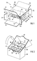
- FIG. 1 shows an unfolded, not closed folding box
- Figure 2 shows a folding box in unfolded state
- Figure 3 shows a first cut of the Folding box according to Figures 1 and 2
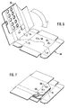
- Figures 4 to 9 den Folding process of the folding box from the cut according to the figure 3, all figures being shown in a perspective view.
- FIG. 1 Made from a stiff packaging material, preferably cardboard, existing cuboidal folding box (Figure 1) has one sleeve-shaped fuselage 10 with two parallel to each other Broad side walls 11, 12 and two parallel to each other Narrow side walls 13, 14. Which is a narrow side wall 14 on its inner surface with one on the broad side wall 11 hinged, trapezoidal longitudinal adhesive tab 15 glued.
- the bottom and lid end faces of the fuselage 10 are by articulated on the side walls 11 to 14, in the respective end faces folded and together glued locking tabs 16 to 23 lockable.
- FIGS. 2 and 3 To open the cover part 25 from the bottom part 26 is the Folding box equipped with a perforation 27. On the Perforation 27 will be discussed in more detail later.
- an insert 30 in the Bottom part 26 is an insert 30 with openings 31 for positive reception of shock-sensitive objects such as ampoules, vials, vials or the like.
- the insert 30 consists of two backdrop walls 32, 33 which parallel and at certain intervals to the End faces of the fuselage 10 extend in the bottom part 26.
- the Scenery walls 32, 33, whose width b is smaller than that Width B of the narrow side walls 13, 14 are by means of a these connecting webs 35 via the longitudinal adhesive tab 15 connected to the broad side wall 11 (see FIG. 3).
- the width h of the longitudinal adhesive tab 15 is somewhat less than the width B of the narrow side walls 13, 14. This is therefore necessary so that the folding box in the glued, not yet erected state completely can be stored flat.
- the narrow one Tab 38 which has the width c, has a U-shaped center Cutout 41, which on the web 35th opposite side is open.
- the broad rag 39 whose width d is approximately the sum of the width c of the narrow Flap 38 and the width e of the web 35 corresponds, points at its corners facing away from the backdrop wall 33 an approximately rectangular cutout 42.
- the width b is the size of the intermediate wall 36 the size or the leaflet can be adjusted.
- folding box exists preferably made of cardboard.
- the cardboard is smooth on one side painted.
- the smooth painted exterior the outer appearance of the folding box.
- the smooth outside lies below.
- the blank 46 has the side opposite the longitudinal adhesive tab 15 on the web 35 still another, rectangular tab 47. This Tab 47 is in the folded state of the folding box the narrow side wall 13.
- FIG 27 The arrangement of the perforation is also shown in FIG 27 in the side walls 11 to 14 and the longitudinal adhesive tab 15 evident.
- the Perforation 27 along the wide side walls 11, 12 parallel to the broad sides of the locking tabs 16 to 19.
- the perforation 27 runs in the narrow side walls 13, 14 obliquely to the broad sides of the locking tabs 20 to 23.
- the longitudinal adhesive tab 15 has the perforation 27 also oblique, and ends near the narrow end face 48 of the web 35.
- To reclose the opened To enable cover part 25 with the bottom part 26 is the Perforation 27 in the broad side wall 12 semicircular or semi-lymphatic.
- the so shaped Locking tab 49 is in a corresponding, in the web 35th trained curved incision 50 insertable.
- the folding box can be seen from the above Make blank 46 as follows ( Figures 4 to 8): First, the backdrop wall 33 together with the wide one Tab 39 folded flat around the fold line 51 on the web 35, and the wide tab 39 by means of two, on the narrow tab 38 Adhesive dots 52 attached to both sides of the cutout 41 connected ( Figure 4).
- the flap 47 is by means of a suitable device of the folding and gluing machine held, so that the web 35 at the above Fold is positioned.
- the insert 30 is then on the fold line 53 folded between the web 35 and the longitudinal adhesive tab 15 ( Figure 5). Then we cut part of the blank 46 together Insert 30 around fold line 54 between the broad side wall 11 and the narrow side wall 13 folded. Previously are on the Broad side wall 12 two adhesive points 55, 56 applied been ( Figure 6).
- the arrangement of the adhesive dots 55, 56 is such that after flipping the tab 47 on the The narrow side wall 13 lies loosely and at the same time the web 35 are connected to the broad side wall 12.
- Last will be three adhesive dots 58 applied to the longitudinal adhesive tab 15 (Figure 7), and the narrow side wall 14 against the Longitudinal adhesive tab 15 folded ( Figure 8). In this stadium the folding box is completely folded and (except for the Glue the locking tabs 16 to 23) glued, and leaves stock up flat ( Figure 9). To fill the Folding box with items and an insert with the The flat-packed carton can be packed by further process known cartoning machines.
- the folding box described above and its cut 46 has the advantage that it can be folded with a few is producible, so that it is based on conventional adhesive and Folding machines glued and folded in one pass can be. This is made possible by the fact that the Insert 30 on the narrow end face 48 of the web 35 the longitudinal adhesive tab 15 connects, and the broad sides of the web 35 parallel to the broad sides of the Broad side walls 11, 12 extend. Through training and Arrangement of the perforation 27 and the possible Unfolding the carton will still be a good one Accessibility and easy removal of the in the Folding box arranged objects allows. At the same time, there is an advantageous one Presentation effect and a good overview of the Objects in the folding box, as well as through the Locking tab 49 a simple reclosure option.
Landscapes
- Engineering & Computer Science (AREA)
- Mechanical Engineering (AREA)
- Cartons (AREA)
- Packaging Frangible Articles (AREA)
Description
Claims (5)
- Einteiliger Zuschnitt für eine Faltschachtel, bestehend aus einem steifen Packstoff, wie Karton, mit zwei ersten Seitenwänden (11, 12) und mit zwei diese zu verbindenden zweiten Seitenwänden (13, 14), mit an den freien Enden der Seitenwände (11 bis 14) angelenkten Verschlußlaschen (16 bis 23), mit zwei voneinander beabstandeten Kulissenwänden (32, 33), mit einem die Kulissenwände (32, 33) miteinander verbindenden Steg (35), der mittels eines Zwischenstücks (15) mit einer ersten Seitenwand (11) verbunden ist, wobei das Zwischenstück (15) auf einer einer zweiten Seitenwand (13) gegenüberliegenden Seite an der ersten Seitenwand (11) angeordnet ist, und wobei eine Schmalseite (48) des Steges (35) am Zwischenstück (15) angelenkt ist, so daß sich die Breitseiten der Kulissenwände (32, 33) parallel zu dem Steg (35) erstrecken, dadurch gekennzeichnet, daß das Zwischenstück (15) eine Breite (h) aufweist, die geringer ist, als die Breite (B) der zweiten Seitenwände (13, 14) und daß auf den dem Steg (35) gegenüberliegenden Seiten der Kulissenwände (32, 33) jeweils ein Lappen (38, 39) angeordnet ist.
- Zuschnitt nach Anspruche 1 , dadurch gekennzeichnet, daß auf der dem Zwischenstück (15) gegenüberliegenden Seite am Steg (35) ein weiterer Lappen (47) angeordnet ist, der mit der dem Zwischenstück (15) gegenüberliegenden zweiten Seitenwand (13) verbindbar ist.
- Zuschnitt nach Anspruch 1 oder 2, dadurch gekennzeichnet, daß das Zwischenstück (15) eine trapezförmige Form aufweist.
- Zuschnitt nach einem der Ansprüche 1 bis 3, dadurch gekennzeichnet, daß die ersten Seitenwände als Breitseitenwände (11, 12) und die zweiten Seitenwände als Schmalseitenwände (13, 14) ausgebildet sind.
- Faltschachtel zum Verpacken von Gegenständen mit einem Zuschnitt nach einem der Ansprüche 1 bis 4.
Applications Claiming Priority (3)
| Application Number | Priority Date | Filing Date | Title |
|---|---|---|---|
| DE19526335 | 1995-07-19 | ||
| DE19526335A DE19526335C1 (de) | 1995-07-19 | 1995-07-19 | Zuschnitt für eine Faltschachtel |
| PCT/DE1996/001249 WO1997003886A1 (de) | 1995-07-19 | 1996-07-11 | Einteiliger zuschnitt für eine faltschachtel mit einsatz und aus diesem hergestellte faltschachtel |
Publications (2)
| Publication Number | Publication Date |
|---|---|
| EP0781232A1 EP0781232A1 (de) | 1997-07-02 |
| EP0781232B1 true EP0781232B1 (de) | 2000-11-02 |
Family
ID=7767226
Family Applications (1)
| Application Number | Title | Priority Date | Filing Date |
|---|---|---|---|
| EP96923826A Expired - Lifetime EP0781232B1 (de) | 1995-07-19 | 1996-07-11 | Einteiliger zuschnitt für eine faltschachtel mit einsatz und aus diesem hergestellte faltschachtel |
Country Status (8)
| Country | Link |
|---|---|
| US (1) | US5871145A (de) |
| EP (1) | EP0781232B1 (de) |
| JP (1) | JPH10506355A (de) |
| BR (1) | BR9606525A (de) |
| DE (2) | DE19526335C1 (de) |
| ES (1) | ES2152540T3 (de) |
| PL (1) | PL182292B1 (de) |
| WO (1) | WO1997003886A1 (de) |
Families Citing this family (31)
| Publication number | Priority date | Publication date | Assignee | Title |
|---|---|---|---|---|
| DE19758126A1 (de) * | 1997-12-30 | 1999-07-01 | Sanol Arznei Schwarz Gmbh | Schachtel zur Aufnahme rohrförmiger Elemente |
| US6112978A (en) * | 1999-04-12 | 2000-09-05 | Nintendo Of America Inc. | Integral insert packaging |
| IT1316680B1 (it) | 2000-02-28 | 2003-04-24 | Eikon Grafiche Srl | Fustellato e scatola per fiale e procedimento per la sua confezione |
| GB0031294D0 (en) * | 2000-12-21 | 2001-01-31 | Glaxo Group Ltd | Packaging means |
| US6659280B2 (en) | 2002-02-04 | 2003-12-09 | Howell Packaging, Division Of Fm Howell & Co. | Multi-layered child resistant blister |
| ITMI20020334U1 (it) * | 2002-06-26 | 2003-12-29 | Artsana Spa | Dispositivo per il prelevamento di campioni di sangue da sottoporre aprova ad esempio del tasso di glucosio in esso contenuto |
| USD568733S1 (en) * | 2003-07-03 | 2008-05-13 | Cenetron Diagnostics, Ltd. | Container with view windows |
| ITFI20030313A1 (it) * | 2003-12-05 | 2005-06-06 | Project Sas | Astuccio per fiale in vetro con collo da troncare |
| US20070062842A1 (en) * | 2005-09-19 | 2007-03-22 | Bender Lawrence F | Specimen collection and shipping kit and container therefor |
| US7581642B2 (en) * | 2006-01-09 | 2009-09-01 | Anderson Packaging, Inc. | Child-resistant, senior-friendly unit dose container |
| JP4554709B2 (ja) * | 2006-02-10 | 2010-09-29 | クルティコストルツィオーニ メッカニケ ソチエタ ペル アツィオーニ | 細長い物品を包装するためのブランク、箱、装置、および方法 |
| US7780007B2 (en) * | 2006-11-08 | 2010-08-24 | Graphic Packaging International, Inc. | Multi-layered blister card package and method for making the same |
| US20090031628A1 (en) * | 2007-07-31 | 2009-02-05 | Taikon Corp. | Plant tissue culture display box |
| US20100012544A1 (en) * | 2008-07-18 | 2010-01-21 | Howell Packaging, Division of F.M. Howell & Company | Multi-layered child resistant blister package |
| US20100102110A1 (en) * | 2008-10-29 | 2010-04-29 | Learn Angela E | Carton for a food product |
| FR2965553B1 (fr) * | 2010-10-05 | 2012-10-26 | Saica France | Caisse de transport avec cloisonnement integre |
| US8459482B2 (en) | 2010-12-08 | 2013-06-11 | Christopher M. Wall | Foldable storage case |
| US9101167B2 (en) | 2012-05-24 | 2015-08-11 | Altria Client Services Inc. | Display carton and system for displaying a plurality of containers |
| USD749428S1 (en) | 2012-06-01 | 2016-02-16 | Altria Client Services Llc | Display carton with tubular containers |
| USD749429S1 (en) | 2012-06-01 | 2016-02-16 | Altria Client Services Llc | Display carton with tubular containers |
| WO2014085368A1 (en) | 2012-11-28 | 2014-06-05 | Graphic Packaging International, Inc. | Carton with container |
| US8944248B2 (en) * | 2013-03-13 | 2015-02-03 | R.J. Reynolds Tobacco Company | Blank configured to form a package and related package and method |
| US9738049B2 (en) | 2014-09-11 | 2017-08-22 | R.J. Reynolds Tobacco Company | Blank configured to form a package and related package and method |
| USD787320S1 (en) | 2015-10-05 | 2017-05-23 | Tuesday Morning Partners, Ltd. | Box |
| CN108163311B (zh) * | 2018-02-13 | 2024-11-22 | 东莞市美盈森环保科技有限公司 | 试剂包装盒 |
| JP7523429B2 (ja) | 2018-08-06 | 2024-07-26 | グラフィック パッケージング インターナショナル エルエルシー | 少なくとも1つの区画を備える容器 |
| DE102019206087A1 (de) * | 2019-04-29 | 2020-10-29 | Robert Bosch Gmbh | Verpackungseinheit zur Aufnahme eines Zubehörwerkzeugs |
| US12139312B2 (en) * | 2021-02-17 | 2024-11-12 | R. J. Reynolds Tobacco Co. | Packaging for an aerosol delivery device and consumable components |
| IT202100012815A1 (it) * | 2021-05-18 | 2022-11-18 | Azionaria Costruzioni Acma Spa | Scatola di materiale cartaceo con coperchio e sbozzato per realizzare una scatola di materiale cartaceo con coperchio |
| EP4406566A1 (de) * | 2023-01-27 | 2024-07-31 | Uhlmann Pac-Systeme GmbH & Co. KG | Verpackung und verfahren zum bestücken einer verpackung |
| USD1091334S1 (en) | 2023-05-11 | 2025-09-02 | Graphic Packaging International, Llc | Tray with divider features |
Family Cites Families (17)
| Publication number | Priority date | Publication date | Assignee | Title |
|---|---|---|---|---|
| US1337091A (en) * | 1919-05-17 | 1920-04-13 | Chester W Neski | Paper receptacle |
| US1686273A (en) * | 1925-12-01 | 1928-10-02 | Westinghouse Lamp Co | Lamp wrapper |
| US2069997A (en) * | 1935-11-13 | 1937-02-09 | Edward J Carr | Carton |
| US2128197A (en) * | 1936-10-03 | 1938-08-23 | Stransky Products Corp | Box or carton and blank therefor |
| US2643811A (en) * | 1949-04-14 | 1953-06-30 | Bradley & Gilbert Company | Display carton |
| US3115247A (en) * | 1960-06-10 | 1963-12-24 | Hauser Theodor | Packing for ampoules or the like |
| US3036754A (en) * | 1960-07-25 | 1962-05-29 | Interstate Folding Box Co | Cushioned end closure device for cartons |
| US3182885A (en) * | 1962-11-15 | 1965-05-11 | Continental Folding Paper Box | Containers for fragile articles |
| US3326444A (en) * | 1964-09-02 | 1967-06-20 | Reynolds Metals Co | Multi-compartment carton |
| US3390783A (en) * | 1966-05-17 | 1968-07-02 | Virginia Packaging Supply Comp | Test tube holder or display device |
| US3921895A (en) * | 1974-05-22 | 1975-11-25 | Cea Brevetti Spa | Box for containing vials or the like adapted for automatic loading |
| DE2453309A1 (de) * | 1974-11-11 | 1976-05-20 | Edelmann Carl Gmbh | Faltschachtel fuer die verpackung von ampullen |
| US4160502A (en) * | 1978-04-20 | 1979-07-10 | Champion International Corporation | Platform carton |
| US5121838A (en) * | 1991-10-23 | 1992-06-16 | Intepac Technologies Inc. | Package having product clamping for card-like products |
| DE9214914U1 (de) * | 1992-11-03 | 1993-01-14 | Albert Frey Verpackungsentwicklungen und Vertriebs-GmbH, 8949 Dirlewang | Verpackung mit Originalitätsverschluß |
| DE4309036A1 (de) * | 1993-03-20 | 1994-09-22 | Bosch Gmbh Robert | Faltschachtel zum Verpacken länglicher Gegenstände |
| DE4438699A1 (de) * | 1994-10-29 | 1996-05-02 | Edelmann Carl Gmbh | Faltschachtel aus Karton für die Verpackung von Ampullen |
-
1995
- 1995-07-19 DE DE19526335A patent/DE19526335C1/de not_active Expired - Fee Related
-
1996
- 1996-07-11 DE DE59606088T patent/DE59606088D1/de not_active Expired - Fee Related
- 1996-07-11 PL PL96319158A patent/PL182292B1/pl unknown
- 1996-07-11 US US08/809,322 patent/US5871145A/en not_active Expired - Fee Related
- 1996-07-11 BR BR9606525A patent/BR9606525A/pt not_active IP Right Cessation
- 1996-07-11 ES ES96923826T patent/ES2152540T3/es not_active Expired - Lifetime
- 1996-07-11 JP JP9506148A patent/JPH10506355A/ja not_active Ceased
- 1996-07-11 WO PCT/DE1996/001249 patent/WO1997003886A1/de not_active Ceased
- 1996-07-11 EP EP96923826A patent/EP0781232B1/de not_active Expired - Lifetime
Also Published As
| Publication number | Publication date |
|---|---|
| PL182292B1 (pl) | 2001-12-31 |
| BR9606525A (pt) | 1997-10-14 |
| JPH10506355A (ja) | 1998-06-23 |
| US5871145A (en) | 1999-02-16 |
| ES2152540T3 (es) | 2001-02-01 |
| DE59606088D1 (de) | 2000-12-07 |
| PL319158A1 (en) | 1997-07-21 |
| WO1997003886A1 (de) | 1997-02-06 |
| EP0781232A1 (de) | 1997-07-02 |
| DE19526335C1 (de) | 1997-01-23 |
Similar Documents
| Publication | Publication Date | Title |
|---|---|---|
| DE19526335C1 (de) | Zuschnitt für eine Faltschachtel | |
| EP0616950B1 (de) | Faltschachtel zum Verpacken länglicher Gegenstände | |
| EP1270441A1 (de) | Blisterpackung | |
| DE4418666A1 (de) | Faltschachtel | |
| DE4318312C2 (de) | Verpackung zur Aufnahme eines mindestens zwei Komponenten aufweisenden Produkts | |
| DE4125777C2 (de) | Verpackung mit Griffmulde | |
| EP1371567A2 (de) | Umverpackung | |
| EP1886927A1 (de) | Faltschachtel mit integriertem Füllstück | |
| DE29622339U1 (de) | Faltschachtelzuschnitt aus Karton und Faltschachtel daraus | |
| EP1193180A1 (de) | Faltschachtel mit Innenkammer | |
| EP0021380A1 (de) | Verpackung von Aufklebefolien für Keramikfliesen und Verfahren zum Füllen der Verpackung | |
| EP1259437B1 (de) | Einteiliger zuschnitt für aufklappbares verpackungsbehältnis | |
| EP0340319A1 (de) | Faltschachtel | |
| DE69713029T2 (de) | Faltbarer Verpackungsbehälter | |
| EP0524319A1 (de) | Faltschachtel und Zuschnitte zu ihrer Herstellung | |
| DE19954006A1 (de) | Verpackung, insbesondere aus Wellpappe | |
| DD299819A5 (de) | Behälter | |
| DE9210073U1 (de) | Faltverpackung mit Stecklasche | |
| DE9109704U1 (de) | Faltschachtel für Flaschen u.dgl. | |
| DE2818483A1 (de) | Quaderfoermige endverpackung | |
| DE8901318U1 (de) | Faltschachtel mit doppellagigen Seitenwandteilen | |
| DE29707786U1 (de) | Faltschachtel mit verriegelbarem Wiederverschluß | |
| DE3140886A1 (de) | "kappenschachtel" | |
| DE4033170A1 (de) | Verpackung | |
| EP0995690A1 (de) | Verpackung zur Aufnahme eines schüttfähigen Produktes |
Legal Events
| Date | Code | Title | Description |
|---|---|---|---|
| PUAI | Public reference made under article 153(3) epc to a published international application that has entered the european phase |
Free format text: ORIGINAL CODE: 0009012 |
|
| AK | Designated contracting states |
Kind code of ref document: A1 Designated state(s): CH DE ES FR GB IT LI SE |
|
| 17P | Request for examination filed |
Effective date: 19970806 |
|
| 17Q | First examination report despatched |
Effective date: 19980424 |
|
| GRAG | Despatch of communication of intention to grant |
Free format text: ORIGINAL CODE: EPIDOS AGRA |
|
| GRAG | Despatch of communication of intention to grant |
Free format text: ORIGINAL CODE: EPIDOS AGRA |
|
| GRAH | Despatch of communication of intention to grant a patent |
Free format text: ORIGINAL CODE: EPIDOS IGRA |
|
| GRAH | Despatch of communication of intention to grant a patent |
Free format text: ORIGINAL CODE: EPIDOS IGRA |
|
| GRAA | (expected) grant |
Free format text: ORIGINAL CODE: 0009210 |
|
| AK | Designated contracting states |
Kind code of ref document: B1 Designated state(s): CH DE ES FR GB IT LI SE |
|
| REG | Reference to a national code |
Ref country code: CH Ref legal event code: NV Representative=s name: SCINTILLA AG, DIREKTION Ref country code: CH Ref legal event code: EP |
|
| REF | Corresponds to: |
Ref document number: 59606088 Country of ref document: DE Date of ref document: 20001207 |
|
| ITF | It: translation for a ep patent filed | ||
| GBT | Gb: translation of ep patent filed (gb section 77(6)(a)/1977) |
Effective date: 20010110 |
|
| REG | Reference to a national code |
Ref country code: ES Ref legal event code: FG2A Ref document number: 2152540 Country of ref document: ES Kind code of ref document: T3 |
|
| ET | Fr: translation filed | ||
| PLBE | No opposition filed within time limit |
Free format text: ORIGINAL CODE: 0009261 |
|
| STAA | Information on the status of an ep patent application or granted ep patent |
Free format text: STATUS: NO OPPOSITION FILED WITHIN TIME LIMIT |
|
| 26N | No opposition filed | ||
| REG | Reference to a national code |
Ref country code: GB Ref legal event code: IF02 |
|
| PGFP | Annual fee paid to national office [announced via postgrant information from national office to epo] |
Ref country code: GB Payment date: 20030625 Year of fee payment: 8 |
|
| PGFP | Annual fee paid to national office [announced via postgrant information from national office to epo] |
Ref country code: FR Payment date: 20030716 Year of fee payment: 8 |
|
| PGFP | Annual fee paid to national office [announced via postgrant information from national office to epo] |
Ref country code: ES Payment date: 20030721 Year of fee payment: 8 |
|
| PGFP | Annual fee paid to national office [announced via postgrant information from national office to epo] |
Ref country code: SE Payment date: 20030722 Year of fee payment: 8 |
|
| PGFP | Annual fee paid to national office [announced via postgrant information from national office to epo] |
Ref country code: CH Payment date: 20030723 Year of fee payment: 8 |
|
| PG25 | Lapsed in a contracting state [announced via postgrant information from national office to epo] |
Ref country code: GB Free format text: LAPSE BECAUSE OF NON-PAYMENT OF DUE FEES Effective date: 20040711 |
|
| PG25 | Lapsed in a contracting state [announced via postgrant information from national office to epo] |
Ref country code: SE Free format text: LAPSE BECAUSE OF NON-PAYMENT OF DUE FEES Effective date: 20040712 Ref country code: ES Free format text: LAPSE BECAUSE OF NON-PAYMENT OF DUE FEES Effective date: 20040712 |
|
| PG25 | Lapsed in a contracting state [announced via postgrant information from national office to epo] |
Ref country code: LI Free format text: LAPSE BECAUSE OF NON-PAYMENT OF DUE FEES Effective date: 20040731 Ref country code: CH Free format text: LAPSE BECAUSE OF NON-PAYMENT OF DUE FEES Effective date: 20040731 |
|
| PGFP | Annual fee paid to national office [announced via postgrant information from national office to epo] |
Ref country code: DE Payment date: 20040913 Year of fee payment: 9 |
|
| EUG | Se: european patent has lapsed | ||
| GBPC | Gb: european patent ceased through non-payment of renewal fee |
Effective date: 20040711 |
|
| REG | Reference to a national code |
Ref country code: CH Ref legal event code: PL |
|
| PG25 | Lapsed in a contracting state [announced via postgrant information from national office to epo] |
Ref country code: FR Free format text: LAPSE BECAUSE OF NON-PAYMENT OF DUE FEES Effective date: 20050331 |
|
| REG | Reference to a national code |
Ref country code: FR Ref legal event code: ST |
|
| PG25 | Lapsed in a contracting state [announced via postgrant information from national office to epo] |
Ref country code: IT Free format text: LAPSE BECAUSE OF NON-PAYMENT OF DUE FEES;WARNING: LAPSES OF ITALIAN PATENTS WITH EFFECTIVE DATE BEFORE 2007 MAY HAVE OCCURRED AT ANY TIME BEFORE 2007. THE CORRECT EFFECTIVE DATE MAY BE DIFFERENT FROM THE ONE RECORDED. Effective date: 20050711 |
|
| REG | Reference to a national code |
Ref country code: ES Ref legal event code: FD2A Effective date: 20040712 |
|
| PG25 | Lapsed in a contracting state [announced via postgrant information from national office to epo] |
Ref country code: DE Free format text: LAPSE BECAUSE OF NON-PAYMENT OF DUE FEES Effective date: 20060201 |