EP0779454B1 - Stufenlos regelbares Getriebe - Google Patents
Stufenlos regelbares Getriebe Download PDFInfo
- Publication number
- EP0779454B1 EP0779454B1 EP96119292A EP96119292A EP0779454B1 EP 0779454 B1 EP0779454 B1 EP 0779454B1 EP 96119292 A EP96119292 A EP 96119292A EP 96119292 A EP96119292 A EP 96119292A EP 0779454 B1 EP0779454 B1 EP 0779454B1
- Authority
- EP
- European Patent Office
- Prior art keywords
- pulley
- low
- ratio
- hydraulic
- continuously variable
- Prior art date
- Legal status (The legal status is an assumption and is not a legal conclusion. Google has not performed a legal analysis and makes no representation as to the accuracy of the status listed.)
- Expired - Lifetime
Links
Images


Classifications
-
- F—MECHANICAL ENGINEERING; LIGHTING; HEATING; WEAPONS; BLASTING
- F16—ENGINEERING ELEMENTS AND UNITS; GENERAL MEASURES FOR PRODUCING AND MAINTAINING EFFECTIVE FUNCTIONING OF MACHINES OR INSTALLATIONS; THERMAL INSULATION IN GENERAL
- F16H—GEARING
- F16H37/00—Combinations of mechanical gearings, not provided for in groups F16H1/00 - F16H35/00
- F16H37/02—Combinations of mechanical gearings, not provided for in groups F16H1/00 - F16H35/00 comprising essentially only toothed or friction gearings
- F16H37/06—Combinations of mechanical gearings, not provided for in groups F16H1/00 - F16H35/00 comprising essentially only toothed or friction gearings with a plurality of driving or driven shafts; with arrangements for dividing torque between two or more intermediate shafts
- F16H37/08—Combinations of mechanical gearings, not provided for in groups F16H1/00 - F16H35/00 comprising essentially only toothed or friction gearings with a plurality of driving or driven shafts; with arrangements for dividing torque between two or more intermediate shafts with differential gearing
- F16H37/0833—Combinations of mechanical gearings, not provided for in groups F16H1/00 - F16H35/00 comprising essentially only toothed or friction gearings with a plurality of driving or driven shafts; with arrangements for dividing torque between two or more intermediate shafts with differential gearing with arrangements for dividing torque between two or more intermediate shafts, i.e. with two or more internal power paths
- F16H37/084—Combinations of mechanical gearings, not provided for in groups F16H1/00 - F16H35/00 comprising essentially only toothed or friction gearings with a plurality of driving or driven shafts; with arrangements for dividing torque between two or more intermediate shafts with differential gearing with arrangements for dividing torque between two or more intermediate shafts, i.e. with two or more internal power paths at least one power path being a continuously variable transmission, i.e. CVT
- F16H37/0846—CVT using endless flexible members
-
- F—MECHANICAL ENGINEERING; LIGHTING; HEATING; WEAPONS; BLASTING
- F16—ENGINEERING ELEMENTS AND UNITS; GENERAL MEASURES FOR PRODUCING AND MAINTAINING EFFECTIVE FUNCTIONING OF MACHINES OR INSTALLATIONS; THERMAL INSULATION IN GENERAL
- F16H—GEARING
- F16H61/00—Control functions within control units of change-speed- or reversing-gearings for conveying rotary motion ; Control of exclusively fluid gearing, friction gearing, gearings with endless flexible members or other particular types of gearing
- F16H61/66—Control functions within control units of change-speed- or reversing-gearings for conveying rotary motion ; Control of exclusively fluid gearing, friction gearing, gearings with endless flexible members or other particular types of gearing specially adapted for continuously variable gearings
- F16H61/662—Control functions within control units of change-speed- or reversing-gearings for conveying rotary motion ; Control of exclusively fluid gearing, friction gearing, gearings with endless flexible members or other particular types of gearing specially adapted for continuously variable gearings with endless flexible members
- F16H61/66254—Control functions within control units of change-speed- or reversing-gearings for conveying rotary motion ; Control of exclusively fluid gearing, friction gearing, gearings with endless flexible members or other particular types of gearing specially adapted for continuously variable gearings with endless flexible members controlling of shifting being influenced by a signal derived from the engine and the main coupling
- F16H61/66259—Control functions within control units of change-speed- or reversing-gearings for conveying rotary motion ; Control of exclusively fluid gearing, friction gearing, gearings with endless flexible members or other particular types of gearing specially adapted for continuously variable gearings with endless flexible members controlling of shifting being influenced by a signal derived from the engine and the main coupling using electrical or electronical sensing or control means
-
- F—MECHANICAL ENGINEERING; LIGHTING; HEATING; WEAPONS; BLASTING
- F16—ENGINEERING ELEMENTS AND UNITS; GENERAL MEASURES FOR PRODUCING AND MAINTAINING EFFECTIVE FUNCTIONING OF MACHINES OR INSTALLATIONS; THERMAL INSULATION IN GENERAL
- F16H—GEARING
- F16H37/00—Combinations of mechanical gearings, not provided for in groups F16H1/00 - F16H35/00
- F16H37/02—Combinations of mechanical gearings, not provided for in groups F16H1/00 - F16H35/00 comprising essentially only toothed or friction gearings
- F16H37/06—Combinations of mechanical gearings, not provided for in groups F16H1/00 - F16H35/00 comprising essentially only toothed or friction gearings with a plurality of driving or driven shafts; with arrangements for dividing torque between two or more intermediate shafts
- F16H37/08—Combinations of mechanical gearings, not provided for in groups F16H1/00 - F16H35/00 comprising essentially only toothed or friction gearings with a plurality of driving or driven shafts; with arrangements for dividing torque between two or more intermediate shafts with differential gearing
- F16H37/0833—Combinations of mechanical gearings, not provided for in groups F16H1/00 - F16H35/00 comprising essentially only toothed or friction gearings with a plurality of driving or driven shafts; with arrangements for dividing torque between two or more intermediate shafts with differential gearing with arrangements for dividing torque between two or more intermediate shafts, i.e. with two or more internal power paths
- F16H37/084—Combinations of mechanical gearings, not provided for in groups F16H1/00 - F16H35/00 comprising essentially only toothed or friction gearings with a plurality of driving or driven shafts; with arrangements for dividing torque between two or more intermediate shafts with differential gearing with arrangements for dividing torque between two or more intermediate shafts, i.e. with two or more internal power paths at least one power path being a continuously variable transmission, i.e. CVT
- F16H2037/088—Power split variators with summing differentials, with the input of the CVT connected or connectable to the input shaft
-
- F—MECHANICAL ENGINEERING; LIGHTING; HEATING; WEAPONS; BLASTING
- F16—ENGINEERING ELEMENTS AND UNITS; GENERAL MEASURES FOR PRODUCING AND MAINTAINING EFFECTIVE FUNCTIONING OF MACHINES OR INSTALLATIONS; THERMAL INSULATION IN GENERAL
- F16H—GEARING
- F16H61/00—Control functions within control units of change-speed- or reversing-gearings for conveying rotary motion ; Control of exclusively fluid gearing, friction gearing, gearings with endless flexible members or other particular types of gearing
- F16H61/12—Detecting malfunction or potential malfunction, e.g. fail safe; Circumventing or fixing failures
- F16H2061/1204—Detecting malfunction or potential malfunction, e.g. fail safe; Circumventing or fixing failures for malfunction caused by simultaneous engagement of different ratios resulting in transmission lock state or tie-up condition
-
- F—MECHANICAL ENGINEERING; LIGHTING; HEATING; WEAPONS; BLASTING
- F16—ENGINEERING ELEMENTS AND UNITS; GENERAL MEASURES FOR PRODUCING AND MAINTAINING EFFECTIVE FUNCTIONING OF MACHINES OR INSTALLATIONS; THERMAL INSULATION IN GENERAL
- F16H—GEARING
- F16H61/00—Control functions within control units of change-speed- or reversing-gearings for conveying rotary motion ; Control of exclusively fluid gearing, friction gearing, gearings with endless flexible members or other particular types of gearing
- F16H61/66—Control functions within control units of change-speed- or reversing-gearings for conveying rotary motion ; Control of exclusively fluid gearing, friction gearing, gearings with endless flexible members or other particular types of gearing specially adapted for continuously variable gearings
- F16H2061/6604—Special control features generally applicable to continuously variable gearings
- F16H2061/6614—Control of ratio during dual or multiple pass shifting for enlarged ration coverage
-
- F—MECHANICAL ENGINEERING; LIGHTING; HEATING; WEAPONS; BLASTING
- F16—ENGINEERING ELEMENTS AND UNITS; GENERAL MEASURES FOR PRODUCING AND MAINTAINING EFFECTIVE FUNCTIONING OF MACHINES OR INSTALLATIONS; THERMAL INSULATION IN GENERAL
- F16H—GEARING
- F16H61/00—Control functions within control units of change-speed- or reversing-gearings for conveying rotary motion ; Control of exclusively fluid gearing, friction gearing, gearings with endless flexible members or other particular types of gearing
- F16H61/16—Inhibiting or initiating shift during unfavourable conditions, e.g. preventing forward reverse shift at high vehicle speed, preventing engine over speed
Definitions
- the invention relates to a continuously variable transmission using a belt-type continuously variable transmission apparatus which has primary and secondary pulleys comprising two sheaves respectively and a belt wound around the primary and secondary pulleys, more specifically to a mode control of a continuously variable transmission which is suitable for vehicle use and realized by combining a belt-type continuously variable transmission apparatus with a planetary gear to provide both low and high modes for a variety of pulley ratios in a predetermined pulley-ratio range.
- a belt-type continuously variable transmission apparatus employed in a continuously variable transmission has primary and secondary pulleys respectively comprising two sheaves, that is, a fixed sheave and a movable sheave and a belt wound around the primary and secondary pulleys.
- a pulley ratio can be changed. More specifically, the pulley ratio is decreased when the narrowing pressure on the primary side is raised. On the other hand, the pulley ratio is increased when the narrowing pressure on the secondary side is raised.
- the rotations of a sun gear and a carrier of the planetary gear can be adjusted properly in accordance with the value of the pulley ratio. In this way, the rotation of a ring gear and an output shaft as an integral body can be set in the normal direction, stopped or set in the reverse direction in order to establish a forward drive state, a neutral state or a backward drive state respectively.
- the belt-type continuously variable transmission apparatus further incorporates two clutches. By changing the clutch engagement state from one to another, a low mode with a high torque ratio and a high mode with a low torque ratio can be set within a limited pulley-ratio range as is already known.
- the pulley ratio can be changed from a high value to a low one.
- the low mode is for a forward drive state at a low speed, the neutral state and the backward drive state.
- the high mode is for a forward drive state at a gradually increasing speed in a high speed range. That is to say, for a variety of pulley ratios, two modes, that is, the low and high modes are available. For this reason, if the clutch engagement state is changed from one to another when the pulley ratio is not within a predetermined pulley-ratio range, jump shift is resulted in.
- the vehicle state is switched from a forward drive at a high speed to a backward drive, which gives rise to a problem of an unexpected backward drive.
- the vehicle state may change from a forward drive at a high speed to a forward drive at a low speed, which causes over revolution of an engine.
- the transmission includes a variable-speed shaft comprising a variable-diameter drive and driven sheave coaxially affixed to a shaft, respectively.
- An endless belt is drivingly trained around the sheaves, whereby the diameter of the sheaves is respectively established by hydraulically-actuated control cylinders and coaxially affixed to movable sheave faces of the drive and driven sheaves.
- a feeler arm rides in a groove of the drive sheave control cylinder to indicate the position of said cylinder.
- the transmission comprises hydraulically actuated high, low and reverse clutches which are controlled by valves. The range and velocity of the transmission is shifted by transverse motion of a control lever.
- a continuously variable transmission comprising: an input shaft associated with an engine output shaft; an output shaft associated with vehicle wheels; a belt-type continuously variable transmission apparatus comprising a first pulley associated with the input shaft, a second pulley provided on the side of the output shaft and a belt wound around the first and second pulleys; and a planetary gear interposed between the input and output shafts.
- a transmission path between the input and output shafts is changed so that any pulley ratio in a pulley-ratio range of the belt-type continuously variable transmission apparatus can correspond to a low mode with a high torque ratio and a high mode with a low torque ratio.
- the continuously variable transmission further comprises: low-high switching means for switching operation between the low and high modes; detecting means for detecting the pulley ratio of the belt-type continuously variable transmission apparatus; and inhibition means for inhibiting switching operation between the low and high modes by preventing the low-high switching means from operating if a pulley ratio detected by the detecting means is within a predetermined pulley-ratio range.
- the continuously variable transmission further comprises a first clutch which has a first hydraulic servo and is engaged to set the low mode when a hydraulic pressure is applied to the first hydraulic servo, and a second clutch which has a second hydraulic servo and is engaged to set the high mode when a hydraulic pressure is applied to the second hydraulic servo.
- the low-high switching means has a low-high switching valve for switching operation to selectively supply the hydraulic pressure to either of the first and second hydraulic servos.
- the low-high switching valve has a spool for switching a supply path of the hydraulic pressure to selectively supply the hydraulic pressure to either of the first and second hydraulic servos in accordance with an output signal from the detecting means, and the inhibition means has a lock member for locking the spool if the pulley ratio is within a predetermined pulley-ratio range.
- the first and second pulleys are respectively provided with movable sheaves for changing a narrowing pressure of the belt to change the pulley ratio.
- the detecting means has a position detecting member which has a protrusion/dent portion formed thereon for engaging and disengaging one end of the lock member and is movable in an associated manner with either of the movable sheaves. And the other end of the lock member locks and unlocks the spool by engaging and disengaging the one end of the lock member with and from the protrusion/dent portion respectively.
- the planetary gear comprises a first rotary element connected to the input shaft, a second rotary element connected to the second pulley and a third rotary element connected to the output shaft, and the input shaft and the first rotary element are connected to each other by the first clutch, and two of the first, second and third rotary elements are connected to each other by the second clutch.
- the inhibition means prevents the low-high switching means from switching operation between a low mode and a high mode.
- the pulley ratio enters the predetermined pulley-ratio range in the low mode the low mode is sustained and operation cannot be switched to the high mode.
- the pulley ratio enters the predetermined pulley-ratio range in the high mode on the other hand, the high mode is sustained and operation cannot be switched to the low mode. In either case, when the pulley ratio enters the predetermined pulley-ratio range in a certain mode, that mode is sustained and operation cannot be switched to another mode.
- predetermined pulley-ratio range described above within a range in which the rotational speed greatly increases when operation is switched from the high mode to the low mode. It is desirable as well to set the predetermined pulley-ratio range within a range in which the vehicle state is inverted from a forward drive to a backward drive when operation is switched from the high mode to the low mode as well as within a range in which the output shaft rotates at a high speed with the high mode taken as a reference and an operation is carried out to switch from the high mode to the low mode.
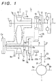
- an automatic continuously variable transmission 1 which is referred to hereafter simply as a continuously variable transmission, comprises a first shaft 3 linked to an engine crank shaft 2, a second shaft 5 and third right and left acceleration shafts 6a and 6b linked to the vehicle front wheels.
- the first shaft 3 supports a primary (first) pulley 7 while the second shaft 5 supports a secondary (second) pulley 9.
- a belt 10 is wound around these primary and secondary pulleys 7 and 9 to constitute a belt-type continuously variable transmission apparatus 11.
- first shaft 3 is linked to the engine crank shaft 2 by way of a damper 12.
- An input-side member 13 of a low clutch C L is fixed on the first shaft 3 while an output-side member 15 thereof is rotatably supported by the first shaft 3.
- a primary-side sprocket 16 forming a power transmitting means is linked integrally to the output-side member 15.
- a fixed sheave 7a of the primary pulley 7 is fixed to the first shaft 3 and an oil pump 17 is attached to the end of the first shaft 3.
- a movable sheave 7b of the primary pulley 7 is supported by the fixed sheave 7a movably in the shaft direction.
- the secondary pulley 9 is rotatably supported by the second shaft 5.
- the secondary pulley 9 comprises a fixed sheave 9a, a movable sheave 9b supported by the fixed sheave 9a movably in the shaft direction and a secondary shaft 9c integrally linked to the fixed sheave 9a.
- a high clutch C H is provided between the second shaft 5 and the secondary shaft 9c.
- a planetary gear 19 is provided on the second shaft 5 and a secondary-side sprocket 20 is rotatably supported by the planetary gear 19.
- An output gear 21 is fixed on one end of the second shaft 5 to form an output shaft.
- the planetary gear 19 comprises a sun gear 19s, a ring gear 19r, a pinion 19p engaged with both the sun and ring gears 19s and 19r and a single pinion planetary gear having a carrier 19c for rotatably supporting the pinion 19p.
- the sun gear 19s is linked to the secondary shaft 9c, serving as a second rotary element while the ring gear 19r is linked to the second shaft 5, serving as a third rotary element.
- the first rotary element 19c is linked to the secondary-side sprocket 20, serving as a first rotary element.
- a wound component 22 such as a silent chain, a roller chain or a timing belt is wound around the primary-side and secondary-side sprockets 16 and 20.
- the gear 21 fixed on the second shaft 5 is engaged with a large gear 23a of a speed reducing gear unit 23 and a small gear 23b of the speed reducing gear unit 23 is engaged with a ring gear 24 of a differential apparatus 25.
- the differential apparatus 25 produces a differential rotation to each of the left and right acceleration shafts 6a and 6b constituting the third shaft 6.
- variable speed rotation of the primary pulley 7 is transmitted to the secondary pulley 9.
- the variable speed rotation of the secondary pulley 9 is further transmitted to the sun gear 19s of the planetary gear 19.
- the carrier 19c to which a constant speed rotation is transmitted by way of the power transmitting apparatus 26 becomes a reactive element, transmitting the continuously variable speed rotation from the belt-type continuous variable transmission apparatus (CVT) 11 to the sun gear 19s.
- the rotations of the carrier 19c and the sun gear 19s are combined before being transmitted to the second shaft 5 by way of the ring gear 19r. Since the ring gear 19r, a rotary element other than the reactive support element, is linked to the second shaft 5, the planetary gear 19 creates a torque environment and, at the same time, the sun gear 19s and the carrier 19c rotate in the same direction.
- the second shaft 5 rotates in the forward (Low) and reverse (Rev) directions, crossing the zero rotational speed. That is to say, in the torque environment, in the state of a normal direction (forward direction) rotation of the second shaft 5, the belt-type continuously variable transmission apparatus 11 transmits a torque from the secondary pulley 9 to the primary pulley 7 but, in the state of a reverse direction (backward direction) rotation of the second shaft 5, a torque is transmitted from the primary pulley 7 to the secondary pulley 9.
- the transmission of power to the planetary gear 19 by way of the power transmitting apparatus 26 is cut off.
- the engagement of the high clutch C H puts the planetary gear 19 in an integrally rotating state.
- the rotation of the first shaft 3 is transmitted to the second shaft 5 by way of the belt-type continuously variable transmission apparatus 11 and the high clutch C H . That is to say, the belt-type continuously variable transmission apparatus 11 transmits power from the primary pulley 7 to the secondary pulley 9.
- the rotation of the second shaft 5 is transmitted to the differential apparatus 25 by way of the output gear 21 and the speed reducing gear unit 23 as well as to the right and left front wheels by way of the right and left acceleration shafts 6a and 6b respectively.
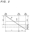
- an output torque diagram of Fig. 3 a diagram of the output rotational speed of Fig. 4, and a clutch engagement table of Fig. 5, in the low mode, that is, when the CVT 11 is at the limit (the O/D end) of the O/D (overdrive) direction (the position of a line (a) shown in Fig. 2), based on the fact that the sun gear 19s is rotating at a maximum speed, the rotation of the ring gear 19r is reversed into a reverse (REV) rotation relative to the rotation of the carrier 19c which is rotating at a constant speed and the reverse (REV) rotation is transmitted to the second shaft 5.
- REV reverse
- the rotational speed in the reverse direction decreases, arriving at a neutral position (an NEU position) at which the rotational speed of the second shaft 5 is reduced to a zero at a predetermined pulley ratio determined by the gear ratios of the planetary gear 19 and the power transmitting apparatus 26.
- the rotation of the ring gear 19r is switched to the normal direction, and the rotation in the normal direction, that is, in the forward drive direction is transmitted to the second shaft 5.
- the torque produced by the second shaft 5 increases to an infinite value in a region in close proximity to the neutral (NEU) position as is obvious from Fig. 3.
- the high clutch C H When the CVT 11 is at the limit (the U/D end) of the U/D direction, the high clutch C H is engaged and an operation to switch to the high mode is carried out.
- the output torque and the output rotational speed are continuous.
- the output rotation of the CVT 11 is transmitted to the second shaft 5 as it is.
- the speed line is parallel to the horizontal axis as shown by a line (b) in the speed diagram of Fig. 2.
- ⁇ shown in Fig. 2 is a ratio of the sun gear tooth count Zs to the ring gear tooth count Zr (that is, Zs/Zr).
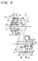
- the movable sheave 7b of the primary pulley 7 is supported movably in the shaft direction by a boss 7c of the fixed sheave 7a of the primary pulley 7 by way of a ball spline 30.
- the movable sheave 9b of the secondary pulley 9 is supported movably in the shaft direction by a boss 9c of the fixed sheave 9a of the secondary pulley 9 by way of a ball spline 31.
- a primary-side hydraulic servo 32 serving as an axial force applying means for applying an axial force to the primary pulley 7 is provided.
- a secondary-side hydraulic servo 33 serving as an axial force applying means for applying an axial force to the secondary pulley 9 is provided.
- the primary-side hydraulic servo 32 comprises a partition member 35 fixed to the fixed sheave 7c, a cylinder member 37, a drum member 40 fixed to the back surface of the movable sheave 7b and a second piston member 42.
- the secondary-side hydraulic servo 33 comprises a partition member 36 fixed to the fixed sheave 9c, a cylinder member 39, a drum member 41 fixed to the back surface of the movable sheave 9b and a second piston member 43.
- the partition member 35 is fitted to the drum member 40 in a hydraulic-sealed state and also fitted to the second piston member 42, the cylinder member 37 and the partition member 35 to form a double piston structure comprising a first hydraulic chamber 45 and a second hydraulic chamber 47.
- the partition member 36 is fitted to the drum member 41 in a hydraulically sealed state and also fitted to the second piston member 43, the cylinder member 39 and the partition member 36 to form a double piston structure comprising a first hydraulic chamber 46 and a second hydraulic chamber 49.
- the back surface of the movable sheave 7b forms a piston surface on the primary side.
- the back surface of the movable sheave 9b forms a piston surface on the secondary side.
- An effective pressure receiving area on the piston surface on the primary side is equal to an effective pressure receiving area on the secondary side.
- hydraulic paths 50 and 52 connected to the first and second hydraulic chambers 45 and 47 are formed on the boss 7c of the fixed sheave 7b on the primary side.
- hydraulic paths 51 and 53 connected to the first and second hydraulic chambers 46 and 49 are formed on the boss 9c of the fixed sheave 9a on the secondary side.
- a spring 55 for preloading use is provided in the first hydraulic chamber 45 of the primary-side hydraulic servo 32.
- a hydraulic control mechanism (means) 54 employed in the present embodiment comprises a primary regulator valve 56, a ratio control valve 57, a down-shift relief valve 58, a manual valve 59, a low-high control valve (or a low-high switching valve) 60 serving as a low-high switching means, a low clutch relief valve 61 and a clutch modulation valve 62.
- the hydraulic control mechanism 54 also includes a ratio sensing valve 63, a sensor shoe 65 used as a detecting means (a position detecting means) and an interlock rod 66 serving as inhibition means (lock member).
- the low-high control valve 60 has a spool 60c which is used for switching a hydraulic pressure supplying path in accordance with on and off operations of a solenoid valve, not shown in the figure, when an on/off signal based on a pulley ratio found from the rotational speeds of the pulleys 7 and 9 is supplied to the solenoid valve.
- the spool 60c has dents 60a and 60b and protrusions at locations other than those of the dents 60a and 60b.
- the sensor shoe 65 is supported slidably by a guide member 67 installed in parallel to the axis of the primary pulley 7.
- Two linkage portions 65b and 65c protrude from the sensor 65.
- the linkage portion 65b is engaged with the movable sheave 7b of the primary pulley 7 while the linkage portion 65c is engaged with the ratio sensing valve 63 cited above.
- a dent 65a is formed on the sensor shoe 65 in addition to a protrusion formed at a location other than that of the dent 65a.
- a base end 66a one end of the interlock rod 66, is engaged with and disengaged from the dent 65a.
- the interlock rod 66 is installed so as to pass through a valve body.
- the other end 66b of the interlock rod 66 is engaged with and disengaged from the dents 60a and 60b of the low-high control valve 60.
- Fig. 7 shows the interlock rod 66 which is split into the base end 66a and the other end 66b. It should be noted, however, that in actuality, the interlock rod 66 is a single rod.
- the other end 66b is engaged with neither the dent 60a nor the dent 60b of the low-high control valve 60. Instead, the other end 66b is brought into contact with a protrusion on the surface of the low-high control valve 60.
- the base end 66a of the interlock rod 66 is disengaged from the dent 65a of the sensor shoe 65 and brought into contact with the protrusion on the surface of the sensor shoe 65, on the contrary, the other end 66b is engaged with either the dent 60a or the dent 60b of the low-high control valve 60.
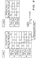
- a first pulley ratio A shown in Fig. 4 is a pulley ratio in a neutral state and a second pulley ratio B is greater than the first pulley ratio A.
- a vertical line passing through the second pulley ratio B is the border between a region with high pulley ratios on the left side of the figure and a region with low pulley ratios on the right side of the figure.
- the low and high modes of the drive (D) ranges (1) and (2) are set by changing control in the regions on the left and right sides of the second pulley ratio B. By changing the control in this way, as will be described later, a down shift is inhibited in the low mode of the drive range and in the reverse (R) range in the region below the second pulley ratio B. Also in the region below the second pulley ratio B, a jump from the high mode of the drive D range to the low mode of the drive range and to the reverse range is inhibited.
- a hydraulic pressure from the oil pump 17 is appropriately regulated by the primary regulator valve 56 and output from an output port (v) thereof as shown in Fig. 7.
- the regulated hydraulic pressure is also supplied to the first hydraulic chambers 45 and 46 of the hydraulic servos 32 and 33 respectively. Control is carried out so as to produce hydraulic pressures in both the first hydraulic chambers 45 and 46 equal to each other.
- the regulated hydraulic pressure is also supplied to the clutch modulation valve 62.
- a hydraulic pressure output by the clutch modulation valve 62 is selectively supplied to the low clutch C L or the high clutch C H except during the N and P ranges (4). Operations in the modes and ranges (1) to (4) are described one mode/range after another by referring to Figs. 4 and 7 as well as a narrowing force balance table shown in Fig. 9.
- Equal hydraulic pressures are supplied to the first hydraulic chambers 45 and 46 respectively.
- the low clutch C L is engaged and, in an up shift, a hydraulic pressure is further supplied to the second hydraulic chamber 49.
- a hydraulic pressure is supplied to the second hydraulic chamber 47 but, in the region below the second pulley ratio B, the supply of the hydraulic pressure is halted, inhibiting the down shift.
- the manual valve 59 is operated at a D range position, opening hydraulic paths between a port (a) and a port (b), a port (c) and a port (d) as well as a port (e) and a port (f) thereof.
- the low-high control valve 60 is set at an L mode position, opening hydraulic paths between a port (h) and a port (i), a port (j) and a port (k) as well as a port (l) and a port (m) thereof.
- a switching operation is carried out to open a hydraulic path between a port (g) and a drain port Ex of the low-high control valve 60 and sustain the hydraulic path in this state.
- the hydraulic pressure from the clutch modulation valve 62 is supplied to the low clutch C L by way of the ports (a) and (b) of the manual valve 59, the ports (h) and (i) of the low-high control valve 60 and ports (n) and (o) of the low clutch relief valve 61, putting the low clutch C L in an engaged state.
- the hydraulic pressure from the output port (v) of the primary regulator valve 56 is gradually increased by the ratio control valve 57 to a value corresponding to a target pulley ratio.
- the gradually increasing hydraulic pressure is then supplied to the second hydraulic chamber 49 through ports (p) and (q) of the ratio control valve 57, the ports (c) and (d) of the manual valve 59 and the ports (j) and (k) of the low-high control valve 60. It should be noted that, in this state, a hydraulic path between the port (g) of the low-high control valve 60 and the drain port Ex is opened as described above, hence putting the hydraulic chamber of the high clutch C H in a released state.
- the second hydraulic chamber 47 of the primary-side hydraulic servo 32 has a hydraulic path opened to a drain port Ex of the down-shift relief valve 58 by way of ports (m) and (l) of the low-high control valve (the low-high switching valve or low-high switching means) 60, the ports (f) and (e) of the manual valve 59 and a port (s) of the down-shift relief valve 58.
- the low clutch C L is engaged and, at the same time, in the CVT 11, an axial force generated by the secondary-side hydraulic servo 33 in which hydraulic pressures are applied to both the first and second hydraulic chambers 46 and 49 exceeds an axial force generated by the primary-side hydraulic servo 32 in which a hydraulic pressure is applied to only the first hydraulic chamber 45.
- the axial force generated by the secondary-side hydraulic servo 33 is further increased gradually to raise the pulley ratio. At that time, the movable sheave 7b of the primary pulley 7 is moved to the U/D side.
- the pulley ratio is gradually increased.
- the operation of the low-high control valve 60 driven by the on/off operations of the solenoid valve is inhibited. That is to say, in an up shift, the movable sheave 7b of the primary pulley 7 is moved to the U/D side and the sensor shoe 65 associated with the movable sheave 7b is moved in the downward direction in the figure.
- the base end 66a of the interlock rod 66 is brought into contact with the surface of the sensor shoe 65 without being engaged with the dent 65a.
- the base end 66a of the interlock rod 66 is engaged with the dent 65a of the sensor shoe 65.
- the other end 66b on the opposite side is moved to the right in the figure, freeing the engagement thereof with the dent 60a of the interlock rod 66.
- the operation of the low-high control valve 60 is enabled. It should be noted that, also in the high mode of the drive range, at a pulley ratio below the second pulley ratio B, the low-high control valve 60 is locked mechanically as will be described later.
- a down shift in the low mode of the drive range in the region below the second pulley ratio B is inhibited but enabled in the region above the second pulley ratio B.
- the ratio sensing valve 63 which moves in an associated manner with the movable sheave 7b of the primary pulley 7 by way of the sensor shoe 65 is in a state shown in the figure. In this state, the hydraulic pressure from the port (v) of the primary regulator valve 56 is halted by the ratio sensing valve 63, making it impossible to supply a hydraulic pressure necessary for a down shift to the second hydraulic chamber 47.
- a down shift is possible by virtue of, among other components, the ratio sensing valve 63. That is to say, in the region above the second pulley ratio B, the movable pulley 7b of the primary pulley 7 is moved to the U/D side, driving the ratio sensing valve 63 in the downward direction of the figure by way of the sensor shoe 65. As a result, since the hydraulic path between ports (t) and (u) of the ratio sensing valve 63 is opened, the hydraulic pressure from the primary regulator valve 56 is led to the down-shift relief valve 58 by way of a check valve 69.
- the hydraulic pressure moves the down-shift relief valve 58 in the upward direction of the figure, opening a hydraulic path between a port (r) and the port (s) thereof.
- a hydraulic pressure to the second hydraulic chamber 47 by way of the ports (e) and (f) of the manual valve 59 and the ports (l) and (m) of the low-high control valve 60.
- a down shift can be carried out.
- the second pulley ratio B is set at a location in close proximity to the first pulley ratio A which corresponds to the neutral state, with a change gear ratio of the continuously variable transmission as a whole set at about the same value as the first gear ratio (the first speed) of the ordinary automatic transmission (A/T), the pulley ratio is fixed at the second pulley ratio B, allowing an effective engine brake to function.
- Equal hydraulic pressures are supplied to the first hydraulic chambers 45 and 46 respectively.
- the high clutch C H is engaged and, in an up shift, a hydraulic pressure is further supplied to the second hydraulic chamber 49.
- a hydraulic pressure is supplied to the second hydraulic chamber 47.
- the operation of the low-high control valve 60 is mechanically inhibited.
- the manual valve 59 is placed at the D range position as shown in Fig. 7 as is the case with the low mode explained previously.
- the low-high control valve 60 is switched to the H mode position, opening hydraulic paths between the ports (h) and (g), the ports (j) and (m) and the ports (l) and (k) as well as a hydraulic path between the port (i) and the drain port Ex.
- the hydraulic pressure from the output port (v) of the primary regulator valve 56 is supplied to the hydraulic servo of the high clutch C H by way of the ports (a) and (b) of the manual valve 59 and the ports (h) and (g) of the low-high control valve 60, putting the high clutch C H in an engaged state.
- the hydraulic pressure from the output port (v) of the primary regulator valve 56 is also supplied to the second hydraulic chamber 47 of the primary-side hydraulic servo 32 by way of the ports (p) and (q) of the ratio control valve 57, the ports (c) and (d) of the manual valve 59 and the ports (j) and (m) of the low-high control valve 60.
- the second hydraulic chamber 49 of the secondary-side hydraulic servo 33 has a hydraulic path opened to a drain port Ex of the down-shift relief valve 58 by way of the ports (k) and (l) of the low-high control valve (the low-high switching valve or low-high switching means) 60, the ports (f) and (e) of the manual valve 59 and a port (s) of the down-shift relief valve 58.
- the axial force produced by the primary-side hydraulic servo 32 is also regulated to give an appropriate pulley ratio (that is, an appropriate torque ratio).
- an appropriate pulley ratio that is, an appropriate torque ratio
- the operation of the low-high control valve 60 is mechanically inhibited. This is because, at a pulley ratio equal to or greater than the second pulley ratio B, the movable sheave 7b of the primary pulley 7 is placed on the U/D side shown in the figure and the base end 66a of the interlock rod 66 is engaged with the dent 65a of the sensor shoe 65 while, on the other hand, the other end 66b thereof on the opposite side is out of the dent 60b of the low-high control valve 60 and moves to the right in the figure, enabling the operation of the low-high control valve 60.
- the movable sheave 7b of the primary pulley 7 is placed on the O/D side shown in the figure and the base end 66a of the interlock rod 66 is brought into contact with the surface of the sensor shoe 65 while, on the other hand, the other end 66b thereof on the opposite side is engaged with the dent 60b of the low-high control valve 60.
- the low-high control valve 60 is mechanically locked in a state in which the high mode is sustained, inhibiting the operation thereof.
- the operation of the low-high control valve 60 is mechanically inhibited, be it in the low mode of the drive range or the high mode of the drive range, sustaining the low or high mode as it is.
- the low-high control valve 60 will not operate, which effectively prevents an over revolution of an engine and a backward drive.
- a predetermined hydraulic pressure is supplied to the first and second hydraulic chambers 45 and 47 of the primary-side hydraulic servo 32, the first hydraulic chamber 46 of the secondary-side hydraulic servo 33 and the hydraulic servo of the low clutch C L as shown in Fig. 7. That is to say, in the reverse range, the manual valve 59 is placed at an R range position and the low-high control valve 60 is at an L mode position as shown in the figure. In this state, hydraulic paths between the ports (a) and (b), the ports (c) and (f) as well as the ports (e) and (d) of the manual valve 59 are opened.
- the hydraulic pressure from the output port (v) of the primary regulator valve 56 is supplied to the hydraulic servo of the low clutch C L by way of the ports (a) and (b) of the manual valve 59 and the ports (h) and (i) of the low-high control valve 60.
- the hydraulic pressure from the output port (v) of the primary regulator valve 56 is also supplied to the second hydraulic chamber 47 of the primary-side hydraulic servo 32 by way of the ports (p) and (q) of the ratio control valve 57, the ports (c) and (f) of the manual valve 59 and the ports (l) and (m) of the low-high control valve 60.
- a hydraulic path between the port (s) and the drain port Ex of the down-shift relief valve 58 is opened.
- the low clutch C L is engaged and, at the same time, in the CVT 11, an axial force generated by the primary-side hydraulic servo 32 in which hydraulic pressures are applied to both the first and second hydraulic chambers 45 and 47 exceeds an axial force generated by the secondary-side hydraulic servo 33 in which a hydraulic pressure is applied to only the first hydraulic chamber 46 works, putting the CVT 11 in an axial force state for torque transmission from the primary pulley 7 to the secondary pulley 9.
- the ratio control valve 57 the hydraulic pressure in the second hydraulic chamber 47 of the primary-side hydraulic servo 32 is regulated.
- the axial force produced by the primary-side hydraulic servo 32 is also regulated to give an appropriate pulley ratio.
- the pulley ratio of the CVT 11 has a predetermined O/D value and an engine torque from the first shaft 3 is transmitted to the carrier 19c of the planetary gear 19 by way of the low clutch C L and the power transmitting apparatus 26.
- an engine torque is also transmitted to the sun gear 19s by way of the CVT 11 in which torque transmission from the primary pulley 7 to the secondary pulley 9 is under way. Both the torques are combined in the planetary gear 19 and output to the second shaft 5 as a rotation in the reverse direction by way of the ring gear 19r.
- the supply of a hydraulic pressure to the down-shift relief valve 58 is inhibited by the sensor shoe 65 and the ratio sensing valve 63 as in the case of a pulley ratio equal to or smaller than the second pulley ratio B in the low mode of the drive range.
- a down shift is also inhibited as well.
- the engine brake is not required in particular. Thus, no problem arises whatsoever even if the down shift is inhibited.
- both the low and high clutches C L and C H are disengaged and a predetermined hydraulic pressure is supplied to the first hydraulic chambers 45 and 46 of the primary-side and secondary-side hydraulic servos 32 and 33 respectively.
- a predetermined hydraulic pressure is supplied to the first hydraulic chambers 45 and 46 of the primary-side and secondary-side hydraulic servos 32 and 33 respectively.
- the low-high control valve 60 is sustained in the low mode of the drive range described earlier.
- a hydraulic path between the port (q) and the drain port Ex of the ratio control valve 57 is opened and the ratio sensing valve 63 is held at a position shown in Fig. 7.
- a hydraulic pressure from the output port (v) of the primary regulator valve 56 is supplied only to the first hydraulic chamber 45 of the primary-side hydraulic servo 32 and the first hydraulic chamber 46 of the secondary-side hydraulic servo 33 and is not to either of the valves.
- equal hydraulic pressures are supplied only to the first hydraulic chambers 45 and 46 of the primary-side and secondary-side hydraulic servos 32 and 33 respectively, resulting in about equal axial forces working on both the primary and secondary pulleys 7 and 9.
- a predetermined hydraulic pressure from the primary regulator valve 56 is supplied to the first hydraulic chambers 45 and 46 of the primary-side and secondary-side hydraulic servos 32 and 33 respectively, securing a predetermined axial force corresponding to a transmitted torque so as to prevent the belt from slipping.
- a regulated hydraulic pressure from the ratio control valve 57 is applied to either the second hydraulic chamber 47 of the primary-side hydraulic servo 32 or the second hydraulic chamber 49 of the secondary-side hydraulic servo 33 in order to adjust the ratio of the axial force of the primary pulley 7 to the axial force of the secondary pulley 9 in a transmission operation so as to produce a predetermined pulley ratio.
- the second pulley ratio B is used as a threshold pulley ratio for inhibiting a down shift in the low mode of the drive range as well as a threshold pulley ratio for mechanically inhibiting the operation of the low-high control valve 60 in the low and high modes of the drive range.
- the threshold pulley ratios can also be set at values different from each other.
- the threshold pulley ratio for inhibiting a down shift in the low mode of the drive range can be set at a value closer to the first pulley ratio A while the threshold pulley ratio for mechanically inhibiting the operation of the low-high control valve 60 in the low and high modes of the drive range can be set at a value farther from the first pulley ratio A.
- the threshold pulley ratio for inhibiting a down shift in the low mode of the drive range and the threshold pulley ratio for mechanically inhibiting the operation of the low-high control valve 60 in the low and high modes of the drive (D) range at values determined by actual running conditions of the vehicle.
- the sensor shoe 65 which moves in an associated manner with the movable sheave 7b of the primary pulley 7 is used as a detecting means for detecting the pulley ratio. It should be noted, however, that a sensor shoe which moves in an associated manner with the movable sheave 9b of the secondary pulley 9 can also be used as a detecting means for detecting the pulley ratio in place of the sensor shoe 65.
- the operation to switch from the low mode to the high mode and vice versa is inhibited, effectively allowing a reversal from a forward dive to a backward drive, over revolution of an engine and the like to be avoided.
- the operations of the hydraulic servos for engaging the two clutches can be controlled, preventing the engagement of the clutches to be switched from one to another and, thus, inhibiting an operation to switch from a low mode to a high mode and vice versa.
- the object of the invention can be achieved by taking a simple countermeasure, that is, by merely controlling the operation of the low-high switching valve.
- the position detecting member associated with the movement of the movable pulley which moves in accordance with a change in pulley ratio and the lock member directly actuated by the position detecting member are used for locking and unlocking the spool, resulting in an even more reliable operation.
- the operation to switch from the low mode to the high mode or vice versa as well as the forward drive, neutral and backward drive states can be implemented with ease by changing the engagement from the first clutch to the second clutch or vice versa and varying the pulley ratio.
Landscapes
- Engineering & Computer Science (AREA)
- General Engineering & Computer Science (AREA)
- Mechanical Engineering (AREA)
- Control Of Transmission Device (AREA)
Claims (3)
- Stufenlos regelbares Getriebe mit:wobei die Low-High-Schalteinrichtung (60) ein Low-High-Schaltventil (60) zum Ausführen eines Schaltvorgangs zum selektiven Zuführen des Hydraulikdrucks zur ersten oder zur zweiten Hydraulik-Servoeinrichtung aufweist;einer mit einer Motorausgangswelle (2) verbundenen Antriebswelle (3);einer mit Fahrzeugrädern verbundenen Abtriebswelle (5) ;einer CVT-Vorrichtung (11) mit Riemenantrieb mit einer mit der Antriebswelle (3) verbundenen ersten Riemenscheibe (7), einer zweiten Riemenscheibe (9) auf der Seite der Abtriebswelle (5) und einem um die erste und die zweite Riemenscheibe (7, 9) geführten Riemen (10);einem zwischen der Antriebs- und der Abtriebswelle (3, 5) angeordneten Planetengetriebe (19), wobei ein Kraftübertragungsweg zwischen der Antriebs- und der Abtriebswelle (3, 5) so verändert wird, daß ein beliebiges Scheibenübersetzungsverhältnis in einem Scheibenübersetzungsverhältnisbereich der CVT-Vorrichtung (11) mit Riemenantrieb einem Low-Modus mit einem hohen Drehmomentverhältnis und einem High-Modus mit einem niedrigen Drehmomentverhältnis entsprechen kann;einer Low-High-Schalteinrichtung (60) für einen Schaltvorgang zwischen dem Low- und dem High-Modus;einer Erfassüngseinrichtung (65) zum Erfassen des Scheibenübersetzungsverhältnisses der CVT-Vorrichtung (11) mit Riemenantrieb;einer Blockiereinrichtung (66) zum Blockieren des Schaltvorgangs zwischen dem Low- und dem High-Modus, indem verhindert wird, daß die Low-High-Schalteinrichtung (60) betätigt wird, wenn ein durch die Erfassungseinrichtung (65) erfaßtes Scheibenübersetzungsverhältnis innerhalb eines vorgegebenen Scheibenübersetzungsverhältnisbereichs liegt;einer ersten Kupplung (CL) mit einer ersten Hydraulik-Servoeinrichtung, die eingerückt wird, um den Low-Modus einzustellen, wenn der ersten Hydraulik-Servoeinrichtung ein Hydraulikdruck zugeführt wird; undeiner zweiten Kupplung (CH) mit einer zweiten Hydraulik-Servoeinrichtung, die eingerückt wird, um den High-Modus einzustellen, wenn der zweiten Hydraulik-Servoeinrichtung ein Hydraulikdruck zugeführt wird;
dadurch gekennzeichnet, daß
das Low-High-Schaltventil (60) einen Ventilschieber (60c) zum Schalten eines Zufuhrweges des Hydraulikdrucks zum selektiven Zuführen des Hydraulikdrucks zur ersten oder zur zweiten Hydraulik-Servoeinrichtung gemäß einem Ausgangssignal von der Erfassungseinrichtung (65) aufweist; und
die Blockiereinrichtung (66) ein Blockierelement zum Blockieren des Ventilschiebers aufweist, wenn das Scheibenübersetzungsverhältnis innerhalb eines vorgegebenen Scheibenübersetzungsverhältnisbereichs liegt. - Stufenlos regelbares Getriebe nach Anspruch 1,
wobei die erste und die zweite Riemenscheibe (7, 9) jeweils eine bewegliche Scheibe (7b, 9b) zum Ändern eines auf das Band (10) ausgeübten Kontraktions- oder Verengungsdrucks zum Ändern des Scheibenübersetzungsverhältnisses aufweisen;
die Erfassungseinrichtung (65) ein Positionserfassungselement mit einem darauf ausgebildeten Vorsprung/Vertiefungsabschnitt (65a) aufweist, der mit (von) einem Ende (66a) des Blockierelements (66) in (außer) Eingriff kommt, und das einer der beweglichen Scheiben (7b, 9b) zugeordnet und mit ihr beweglich ist; und
das andere Ende (65b) des Blockierelements (66) den Ventilschieber (60c) blockiert oder entsperrt, indem das eine Ende (66a) des Blockierelements (66) mit (von) dem Vorsprung-/Vertiefungsabschnitt (65a) in (außer) Eingriff kommt. - Stufenlos regelbares Getriebe nach Anspruch 2,
wobei das Planetengetriebe (19) ein mit der Antriebswelle (3) verbundenes erstes Drehelement (19c), ein mit der zweiten Riemenscheibe (9) verbundenes zweites Drehelement (19s) und ein mit der Abtriebswelle (5) verbundenes drittes Drehelement (19r) aufweist;
wobei die Antriebswelle (3) und das erste Drehelement (19c) durch die erste Kupplung (CL) miteinander verbunden werden; und
von dem ersten, zweiten und dritten Drehelement (19c, 19s, 19r) zwei Drehelemente durch die zweite Kupplung (CH) miteinander verbunden werden.
Applications Claiming Priority (6)
| Application Number | Priority Date | Filing Date | Title |
|---|---|---|---|
| JP327664/95 | 1995-12-15 | ||
| JP32766395 | 1995-12-15 | ||
| JP32766495 | 1995-12-15 | ||
| JP32766495A JP3405028B2 (ja) | 1995-12-15 | 1995-12-15 | 無段変速機 |
| JP327663/95 | 1995-12-15 | ||
| JP32766395A JPH09166215A (ja) | 1995-12-15 | 1995-12-15 | 無段変速機 |
Publications (3)
| Publication Number | Publication Date |
|---|---|
| EP0779454A2 EP0779454A2 (de) | 1997-06-18 |
| EP0779454A3 EP0779454A3 (de) | 1998-04-15 |
| EP0779454B1 true EP0779454B1 (de) | 2002-04-17 |
Family
ID=26572592
Family Applications (2)
| Application Number | Title | Priority Date | Filing Date |
|---|---|---|---|
| EP96119292A Expired - Lifetime EP0779454B1 (de) | 1995-12-15 | 1996-12-02 | Stufenlos regelbares Getriebe |
| EP96119291A Expired - Lifetime EP0779453B1 (de) | 1995-12-15 | 1996-12-02 | Stufenloses Getriebe |
Family Applications After (1)
| Application Number | Title | Priority Date | Filing Date |
|---|---|---|---|
| EP96119291A Expired - Lifetime EP0779453B1 (de) | 1995-12-15 | 1996-12-02 | Stufenloses Getriebe |
Country Status (3)
| Country | Link |
|---|---|
| US (2) | US5833571A (de) |
| EP (2) | EP0779454B1 (de) |
| DE (2) | DE69620719T2 (de) |
Families Citing this family (24)
| Publication number | Priority date | Publication date | Assignee | Title |
|---|---|---|---|---|
| DE19622108A1 (de) * | 1996-06-01 | 1997-12-04 | Zahnradfabrik Friedrichshafen | Verfahren zur Steuerung eines CVT |
| US6146308A (en) * | 1996-10-03 | 2000-11-14 | Aisin Aw Co., Ltd. | Creep torque control of infinitely variable transmission |
| US5961414A (en) * | 1997-09-29 | 1999-10-05 | Ford Global Technologies, Inc. | Dual mode continuously variable transmission having multiple torque input paths |
| US5931760A (en) * | 1997-09-29 | 1999-08-03 | Ford Global Technologies, Inc. | Dual mode continuously variable transmission having multiple torque input paths |
| JP3508690B2 (ja) * | 1999-06-02 | 2004-03-22 | 日産自動車株式会社 | 変速比無限大無段変速機の制御装置 |
| US6317672B1 (en) * | 1999-07-15 | 2001-11-13 | Nissan Motor Co., Ltd. | Controller for infinite speed ratio transmission |
| RU2174076C1 (ru) * | 2000-02-23 | 2001-09-27 | Коротков Эдуард Константинович | Универсальная механическая голономная часть передачи с бесступенчатым изменением крутящего момента (и ее варианты) |
| DE10148204A1 (de) * | 2001-09-28 | 2003-04-10 | Zahnradfabrik Friedrichshafen | Stufenloses Getriebe |
| AU2003206639A1 (en) * | 2002-02-07 | 2003-09-02 | Luk Lamellen Und Kupplungsbau Beteiligungs Kg | Methods for regulating the gear ratio of an automatic power-branched transmission, and automatic power-branched transmission |
| JP3964333B2 (ja) * | 2003-02-06 | 2007-08-22 | ジヤトコ株式会社 | 自動変速機の変速油圧装置 |
| DE10310549B3 (de) * | 2003-03-03 | 2004-10-21 | Selle, Hans-Dieter, Dr.-Ing. | Lastschaltgetriebe mit stufenlos verstellbarem Umschlingungsgetriebe und Leistungsverzweigung |
| DE10354705A1 (de) * | 2003-11-22 | 2005-06-30 | Zf Transmission Technologies L.L.C., Batavia | Verfahren zur Einstellung eines optimalen Anpressdruckes an den Scheiben eines Variators eines stufenlosen Getriebes |
| US7770674B2 (en) * | 2006-03-14 | 2010-08-10 | Fallbrook Technologies Inc. | Wheel chair |
| CA2715500A1 (en) * | 2006-08-23 | 2008-02-28 | S.O.E. Technologies Inc. | Mechanical cvt drive train and control method for earth working vehicle |
| JP4898653B2 (ja) * | 2007-12-27 | 2012-03-21 | アイシン・エィ・ダブリュ株式会社 | 車両用動力伝達装置 |
| JP4898654B2 (ja) * | 2007-12-27 | 2012-03-21 | アイシン・エィ・ダブリュ株式会社 | 車両用動力伝達装置 |
| JP2010249263A (ja) * | 2009-04-17 | 2010-11-04 | Toyota Motor Corp | ベルト式無段変速機 |
| US8574110B2 (en) * | 2010-08-02 | 2013-11-05 | Ford Global Technologies, Llc | Transmission producing stepless variable speed ratios |
| US9108511B2 (en) | 2013-04-10 | 2015-08-18 | Ford Global Technologies, Llc | Transfer case |
| US9546720B2 (en) * | 2013-04-17 | 2017-01-17 | Ford Global Technologies, Llc | Torque split continually variable transmission |
| US9194465B2 (en) * | 2013-05-31 | 2015-11-24 | Gm Global Technology Operations, Llc | Hydraulic control system for a continuously variable transmission |
| WO2015086018A2 (de) * | 2013-12-09 | 2015-06-18 | Schaeffler Technologies AG & Co. KG | Cvt-getriebe |
| JP6384761B2 (ja) | 2014-12-11 | 2018-09-05 | いすゞ自動車株式会社 | デュアルクラッチ装置 |
| CN106704526A (zh) * | 2016-12-12 | 2017-05-24 | 郑州市顺意科技有限公司 | 无极变速箱 |
Family Cites Families (17)
| Publication number | Priority date | Publication date | Assignee | Title |
|---|---|---|---|---|
| US3385132A (en) * | 1966-05-23 | 1968-05-28 | Deere & Co | Transmission control |
| US3375734A (en) * | 1966-07-18 | 1968-04-02 | Deere & Co | Transmission and control therefor |
| US3552232A (en) * | 1966-09-26 | 1971-01-05 | Deere & Co | Transmission control |
| FR2522100B1 (fr) * | 1982-02-22 | 1987-04-24 | Valeo | Transmission entre une prise de mouvement et un arbre recepteur, notamment pour vehicule automobile |
| JPS60132161A (ja) * | 1983-12-21 | 1985-07-15 | Fuji Heavy Ind Ltd | 無段変速機の変速比検出装置 |
| US4644820A (en) | 1986-02-03 | 1987-02-24 | General Motors Corporation | Geared-neutral continuously variable transmission |
| US4864889A (en) * | 1986-05-06 | 1989-09-12 | Aisin-Warner Kabushiki Kaisha | Continuously variable transmission |
| JP2923953B2 (ja) * | 1988-09-16 | 1999-07-26 | トヨタ自動車株式会社 | 車両用自動変速機の制御装置 |
| EP0412718B1 (de) * | 1989-08-09 | 1996-10-23 | Toyota Jidosha Kabushiki Kaisha | Hydraulische Steuerung für ein Fahrzeuggetriebesystem, welches Ventile enthält, die die Einschaltung des Rückwärtsganges verhindern |
| JP2875316B2 (ja) * | 1989-12-29 | 1999-03-31 | アイシン・エィ・ダブリュ株式会社 | 車両用無段変速機の制御装置 |
| US5092434A (en) * | 1991-01-30 | 1992-03-03 | Borg-Warner Automotive, Inc | Control strategies for a dual range infinitely variable transmission |
| JP3185400B2 (ja) * | 1992-09-18 | 2001-07-09 | 日産自動車株式会社 | 変速比無限大無段変速機の変速制御装置 |
| JP3401292B2 (ja) * | 1993-05-19 | 2003-04-28 | ジヤトコ株式会社 | 車両用無段変速装置 |
| JP3016409B2 (ja) * | 1993-11-08 | 2000-03-06 | 日産自動車株式会社 | 無限減速比変速機の変速制御装置 |
| JPH07139608A (ja) * | 1993-11-19 | 1995-05-30 | Nissan Motor Co Ltd | 無限減速比変速機の変速制御装置 |
| JP3612773B2 (ja) * | 1995-03-24 | 2005-01-19 | アイシン・エィ・ダブリュ株式会社 | 無段変速機 |
| EP0733831B1 (de) * | 1995-03-24 | 2002-01-09 | Aisin Aw Co., Ltd. | Stufenloses Getriebe |
-
1996
- 1996-12-02 DE DE69620719T patent/DE69620719T2/de not_active Expired - Fee Related
- 1996-12-02 DE DE69626762T patent/DE69626762D1/de not_active Expired - Lifetime
- 1996-12-02 EP EP96119292A patent/EP0779454B1/de not_active Expired - Lifetime
- 1996-12-02 EP EP96119291A patent/EP0779453B1/de not_active Expired - Lifetime
- 1996-12-13 US US08/766,349 patent/US5833571A/en not_active Expired - Fee Related
- 1996-12-13 US US08/766,801 patent/US5788600A/en not_active Expired - Fee Related
Also Published As
| Publication number | Publication date |
|---|---|
| DE69620719T2 (de) | 2002-09-26 |
| US5833571A (en) | 1998-11-10 |
| EP0779454A3 (de) | 1998-04-15 |
| DE69626762D1 (de) | 2003-04-24 |
| EP0779453A2 (de) | 1997-06-18 |
| US5788600A (en) | 1998-08-04 |
| DE69620719D1 (de) | 2002-05-23 |
| EP0779453A3 (de) | 1998-03-18 |
| EP0779454A2 (de) | 1997-06-18 |
| EP0779453B1 (de) | 2003-03-19 |
Similar Documents
| Publication | Publication Date | Title |
|---|---|---|
| EP0779454B1 (de) | Stufenlos regelbares Getriebe | |
| EP0733831B1 (de) | Stufenloses Getriebe | |
| EP0733829B1 (de) | Stufenloses Getriebe | |
| US6835147B2 (en) | Hydraulic pressure controller for automatic transmission | |
| EP0655035B1 (de) | Hydraulisches steuersystem für automatische fahrzeuggetriebe | |
| JPH0745906B2 (ja) | 流体継手のスリップ制御装置 | |
| EP1099884A2 (de) | Steuereinrichtung eines stufenlosen Toroidgetriebes | |
| US4895552A (en) | Control system for transmission | |
| JP3405028B2 (ja) | 無段変速機 | |
| JP3613641B2 (ja) | 無段変速機 | |
| JPH09166215A (ja) | 無段変速機 | |
| JPH0599302A (ja) | 車両用ベルト式無段変速機の油圧制御装置 | |
| JP3498423B2 (ja) | 無段変速機 | |
| JPH10252847A (ja) | 無段変速機の油圧制御装置 | |
| KR20010059184A (ko) | 무단 변속기의 오일펌프 구동장치 | |
| JP2815051B2 (ja) | 無段変速機の制御装置 | |
| JPH06174073A (ja) | 車両用ベルト式無段変速機の油圧制御装置 | |
| JPH0510428A (ja) | 車両用無段変速機の制御装置 | |
| JP2834742B2 (ja) | 自動変速機の油圧制御装置 | |
| JP2692479B2 (ja) | 車両用自動変速機の油圧制御装置 | |
| JP3043765B2 (ja) | 無段変速機の制御装置 | |
| JPH02240438A (ja) | 変速機の油圧制御装置 | |
| JPH03194263A (ja) | 流体継手のロックアップクラッチ締結力制御装置 | |
| JPH05133466A (ja) | 車両用無段変速機の油圧制御装置 | |
| JPH0510425A (ja) | 車両用無段変速機の油圧制御装置 |
Legal Events
| Date | Code | Title | Description |
|---|---|---|---|
| PUAI | Public reference made under article 153(3) epc to a published international application that has entered the european phase |
Free format text: ORIGINAL CODE: 0009012 |
|
| 17P | Request for examination filed |
Effective date: 19961231 |
|
| AK | Designated contracting states |
Kind code of ref document: A2 Designated state(s): DE GB IT |
|
| PUAL | Search report despatched |
Free format text: ORIGINAL CODE: 0009013 |
|
| AK | Designated contracting states |
Kind code of ref document: A3 Designated state(s): DE GB IT |
|
| 17Q | First examination report despatched |
Effective date: 20000714 |
|
| GRAG | Despatch of communication of intention to grant |
Free format text: ORIGINAL CODE: EPIDOS AGRA |
|
| GRAG | Despatch of communication of intention to grant |
Free format text: ORIGINAL CODE: EPIDOS AGRA |
|
| GRAG | Despatch of communication of intention to grant |
Free format text: ORIGINAL CODE: EPIDOS AGRA |
|
| GRAH | Despatch of communication of intention to grant a patent |
Free format text: ORIGINAL CODE: EPIDOS IGRA |
|
| REG | Reference to a national code |
Ref country code: GB Ref legal event code: IF02 |
|
| GRAH | Despatch of communication of intention to grant a patent |
Free format text: ORIGINAL CODE: EPIDOS IGRA |
|
| GRAA | (expected) grant |
Free format text: ORIGINAL CODE: 0009210 |
|
| AK | Designated contracting states |
Kind code of ref document: B1 Designated state(s): DE GB IT |
|
| REF | Corresponds to: |
Ref document number: 69620719 Country of ref document: DE Date of ref document: 20020523 |
|
| PLBE | No opposition filed within time limit |
Free format text: ORIGINAL CODE: 0009261 |
|
| STAA | Information on the status of an ep patent application or granted ep patent |
Free format text: STATUS: NO OPPOSITION FILED WITHIN TIME LIMIT |
|
| 26N | No opposition filed |
Effective date: 20030120 |
|
| PGFP | Annual fee paid to national office [announced via postgrant information from national office to epo] |
Ref country code: IT Payment date: 20081220 Year of fee payment: 13 |
|
| PGFP | Annual fee paid to national office [announced via postgrant information from national office to epo] |
Ref country code: DE Payment date: 20081127 Year of fee payment: 13 |
|
| PGFP | Annual fee paid to national office [announced via postgrant information from national office to epo] |
Ref country code: GB Payment date: 20081126 Year of fee payment: 13 |
|
| GBPC | Gb: european patent ceased through non-payment of renewal fee |
Effective date: 20091202 |
|
| PG25 | Lapsed in a contracting state [announced via postgrant information from national office to epo] |
Ref country code: DE Free format text: LAPSE BECAUSE OF NON-PAYMENT OF DUE FEES Effective date: 20100701 |
|
| PG25 | Lapsed in a contracting state [announced via postgrant information from national office to epo] |
Ref country code: GB Free format text: LAPSE BECAUSE OF NON-PAYMENT OF DUE FEES Effective date: 20091202 |
|
| PG25 | Lapsed in a contracting state [announced via postgrant information from national office to epo] |
Ref country code: IT Free format text: LAPSE BECAUSE OF NON-PAYMENT OF DUE FEES Effective date: 20091202 |