EP0779241B1 - Durchbohr- und Stopfensetz-Vorrichtung für eine Maschine zum Abgeben von Farbstoffen oder ähnlichen flüssigen Produkten - Google Patents
Durchbohr- und Stopfensetz-Vorrichtung für eine Maschine zum Abgeben von Farbstoffen oder ähnlichen flüssigen Produkten Download PDFInfo
- Publication number
- EP0779241B1 EP0779241B1 EP96119165A EP96119165A EP0779241B1 EP 0779241 B1 EP0779241 B1 EP 0779241B1 EP 96119165 A EP96119165 A EP 96119165A EP 96119165 A EP96119165 A EP 96119165A EP 0779241 B1 EP0779241 B1 EP 0779241B1
- Authority
- EP
- European Patent Office
- Prior art keywords
- perforating
- plugging
- container
- nozzle
- dispensing
- Prior art date
- Legal status (The legal status is an assumption and is not a legal conclusion. Google has not performed a legal analysis and makes no representation as to the accuracy of the status listed.)
- Expired - Lifetime
Links
- 239000000975 dye Substances 0.000 title claims description 15
- 239000012530 fluid Substances 0.000 title claims description 15
- 238000004519 manufacturing process Methods 0.000 description 6
- 238000000034 method Methods 0.000 description 6
- 230000008901 benefit Effects 0.000 description 4
- 230000007246 mechanism Effects 0.000 description 4
- 239000002184 metal Substances 0.000 description 4
- 208000027418 Wounds and injury Diseases 0.000 description 3
- 230000004913 activation Effects 0.000 description 3
- 238000001035 drying Methods 0.000 description 3
- 239000000463 material Substances 0.000 description 3
- 210000002105 tongue Anatomy 0.000 description 3
- 230000005540 biological transmission Effects 0.000 description 2
- 238000013459 approach Methods 0.000 description 1
- 238000005452 bending Methods 0.000 description 1
- 230000015572 biosynthetic process Effects 0.000 description 1
- 230000008859 change Effects 0.000 description 1
- 230000000295 complement effect Effects 0.000 description 1
- 150000001875 compounds Chemical class 0.000 description 1
- 238000010276 construction Methods 0.000 description 1
- 230000001276 controlling effect Effects 0.000 description 1
- 230000006378 damage Effects 0.000 description 1
- 238000009472 formulation Methods 0.000 description 1
- 208000014674 injury Diseases 0.000 description 1
- 239000000203 mixture Substances 0.000 description 1
- 230000002093 peripheral effect Effects 0.000 description 1
- 230000008569 process Effects 0.000 description 1
- 230000001105 regulatory effect Effects 0.000 description 1
- 239000002904 solvent Substances 0.000 description 1
- 239000002699 waste material Substances 0.000 description 1
- XLYOFNOQVPJJNP-UHFFFAOYSA-N water Substances O XLYOFNOQVPJJNP-UHFFFAOYSA-N 0.000 description 1
Images




Classifications
-
- B—PERFORMING OPERATIONS; TRANSPORTING
- B67—OPENING, CLOSING OR CLEANING BOTTLES, JARS OR SIMILAR CONTAINERS; LIQUID HANDLING
- B67B—APPLYING CLOSURE MEMBERS TO BOTTLES JARS, OR SIMILAR CONTAINERS; OPENING CLOSED CONTAINERS
- B67B7/00—Hand- or power-operated devices for opening closed containers
- B67B7/24—Hole-piercing devices
-
- B—PERFORMING OPERATIONS; TRANSPORTING
- B01—PHYSICAL OR CHEMICAL PROCESSES OR APPARATUS IN GENERAL
- B01F—MIXING, e.g. DISSOLVING, EMULSIFYING OR DISPERSING
- B01F33/00—Other mixers; Mixing plants; Combinations of mixers
- B01F33/80—Mixing plants; Combinations of mixers
- B01F33/84—Mixing plants with mixing receptacles receiving material dispensed from several component receptacles, e.g. paint tins
-
- B—PERFORMING OPERATIONS; TRANSPORTING
- B01—PHYSICAL OR CHEMICAL PROCESSES OR APPARATUS IN GENERAL
- B01F—MIXING, e.g. DISSOLVING, EMULSIFYING OR DISPERSING
- B01F35/00—Accessories for mixers; Auxiliary operations or auxiliary devices; Parts or details of general application
- B01F35/71—Feed mechanisms
- B01F35/713—Feed mechanisms comprising breaking packages or parts thereof, e.g. piercing or opening sealing elements between compartments or cartridges
- B01F35/7131—Breaking or perforating packages, containers or vials
-
- B—PERFORMING OPERATIONS; TRANSPORTING
- B67—OPENING, CLOSING OR CLEANING BOTTLES, JARS OR SIMILAR CONTAINERS; LIQUID HANDLING
- B67C—CLEANING, FILLING WITH LIQUIDS OR SEMILIQUIDS, OR EMPTYING, OF BOTTLES, JARS, CANS, CASKS, BARRELS, OR SIMILAR CONTAINERS, NOT OTHERWISE PROVIDED FOR; FUNNELS
- B67C7/00—Concurrent cleaning, filling, and closing of bottles; Processes or devices for at least two of these operations
-
- B—PERFORMING OPERATIONS; TRANSPORTING
- B05—SPRAYING OR ATOMISING IN GENERAL; APPLYING FLUENT MATERIALS TO SURFACES, IN GENERAL
- B05B—SPRAYING APPARATUS; ATOMISING APPARATUS; NOZZLES
- B05B15/00—Details of spraying plant or spraying apparatus not otherwise provided for; Accessories
- B05B15/50—Arrangements for cleaning; Arrangements for preventing deposits, drying-out or blockage; Arrangements for detecting improper discharge caused by the presence of foreign matter
Definitions
- the present invention relates to a perforating and plugging device for a machine for dispensing dyes or fluid products in general.
- the invention has been developed particularly but not exclusively in connection with a perforating and plugging device which can easily be fitted in combination with a device for moistening the output nozzles of the dispensing machine.
- the final coloured products are produced by the mixing of predetermined quantities of a series of dyes with a generally much larger quantity of a base product, for example a white or transparent base, in accordance with predetermined formulations.
- the dyes are metered by a dispensing machine from which they are dispensed into a container holding the base.
- An example of a method for metering dyes and of an automatic dispensing machine is described in the patent EP-B-0198856.
- the bases are usually stored in containers which are closed by lids and which, at the required moment and after their lids have been taken off, are placed on a support shelf of the dispensing machine under the output nozzles. If this operation is carried out manually, there is a risk of some of the contents of the container being spilt either before or after the dye-dispensing operations. Above all, manual opening of a container involves a considerable waste of time.
- the containers are not opened completely but their tops are perforated to reduce the risk of the product coming out, the hole then being closed by a pressure plug upon completion of the dispensing operations.
- greater care then has to be taken in the positioning of the container under the nozzles of the dispensing machine to ensure that they are aligned vertically with the hole in the container. This disadvantage increases production times and also introduces the risk of production rejects or inaccuracy in the production of the desired colour should some of the dye not go into the container.
- the object of the present invention is to solve the problems of the prior art by means of a perforating and plugging device which reduces the times taken to produce the finished products, which eliminates the risk of wastage of the base product or of dye or, in general, of the fluid products dispensed by a dispensing machine, and which enables the machine to be used even by unskilled people or at least makes it easier, quicker and more convenient to use, even for large production volumes.
- Another object of the present invention is to provide a perforating and plugging device which is easy to manufacture, fit and maintain, and which can be produced in versions suitable for both industrial and small-scale use.
- the subject of the present invention is a perforating and plugging device for a machine for dispensing dyes and fluid products in general, characterized in that it comprises:
- An advantage of the present invention is that it is not necessary, during dispensing operations, to reposition the container under the perforating member, under the nozzles, or under the plugging member.
- the hole is normally formed in the centre of the circular, upper face of the container. The central position of the hole may not always be convenient for the final user who is forced to turn the container over in order to remove its contents completely.
- the formation of a hole which is not centred in the upper portion of the container which may be more convenient and pleasing to the final user, however, makes it more difficult to position the container under the nozzles of the dispensing machine with the use of the systems of the prior art.
- a further advantage of the present invention is that the container may be perforated in any portion of its upper face, for example, near the cylindrical side wall, so as to facilitate the removal of the fluid product by the final user, in this case also overcoming the disadvantages of the prior art.
- the selection of the position of the hole in the container thus no longer depends upon the need to simplify the dispensing process.
- the perforating, and plugging device is integrated in a device for moistening the nozzles of a dispensing machine, reducing the time during which the nozzles are exposed to the outside atmosphere to the minimum, in order to prevent the known drying phenomenon.
- the corresponding embodiment of the present invention is thus perforating and plugging device of the type indicated above, characterized in that the perforating member is coupled to a device for moistening the at least one nozzle of the dispensing machine and is movable selectively from the perforation position to a position of disengagement in order to free the at least one nozzle from the moistening device and to enable the fluid products to be dispensed through the hole in the container.
- An advantage of the association with the moistening device is that, essentially, the nozzles are uncovered only for the time necessary for the dispensing and not throughout the time necessary for the perforation and plugging of the container also.
- the device may be operated manually or automatically.
- the perforating member, the plugging member and the moistening device when provided, can be connected to a movable body, particularly a slide body, driven by an electric motor the control circuits of which can be connected to or interfaced with the devices for automatically controlling the fluid-dispensing operations.
- an automatic dispensing machine 1 comprises a space 2 in which a shelf 3 is mounted for sliding vertically, a container R, into which predetermined quantities of fluids contained in reservoirs housed in a casing 4 are to be dispensed, being placed on the shelf 3.
- the dispensing machine may have a configuration other than that shown and, for example, may comprise a projecting dispensing head facing a vertically-movable member which in turn may be integrated in system for the manual or automatic supply or handling of the containers such as, for example, a roller system, a movable belt, or the like.
- a perforating and plugging device 10 fitted on the machine comprises a plugging member 42 which, as explained further below, can house a plug 6.
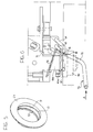
- the perforating and plugging device 10 which is shown in greater detail in Figure 2, comprises a perforating member 12 mounted on a slide 14 movable horizontally on guides fixed below the dispensing head 16 of the dispensing machine, the head being disposed in the space 2 above the shelf 3 of Figure 1.
- the slide is moved horizontally by the activation of an electric motor 15, preferably a direct-current motor, connected to a pinion which meshes with a rack fixed to the slide 14.
- an electric motor 15 preferably a direct-current motor
- the slide 14 may be moved by other mechanisms, for example, by a worm screw, a rod, an electric or hydraulic actuator, a jack or any other linkage, transmission or mechanism driven by an electric, pneumatic, hydraulic or equivalent motor of any kind.
- a punch 18 which, as can be seen in Figures 3 and 4, has an external thread 11 in its upper portion and shaped blades 13 in its lower portion, is screwed into the slide 14, which has a hole which is opposite the supply head 16 when the perforating and plugging device is in its rest position shown in Figure 2.
- the upper wall of the punch 18 has a recess 17 for housing a pack of material impregnated with water or solvent or, in any case, a compound suitable for keeping the fluids dispensed by the machine moistened and preventing their drying out, which would lead to blockage of the output nozzles.
- the perforating member 12 comprises a ring 16 from which a plurality of guide rods 19, of which there are preferably, but not necessarily, four, extend vertically, the rods being able to slide freely in through-holes in the slide 14.
- the maximum downward travel of the ring 16 is defined by travel-limit stops 19a on the upper ends of the guide rods 19.
- a plurality of helical springs 21 wound around the guide rods 19 resiliently opposes upward movement of the ring 16.
- Sensors 27a, 27b are associated with the control pin 23.
- a bar 20 mounted for sliding horizontally on the slide 14 has a pair of adjustable stops, that is, a front stop 22 and a rear stop 24.
- the stops 22, 24 are disposed on opposite sides of an appendage 26 fixed to the slide.
- the front end is preferably fork-shaped.
- the opposite ends of the guide rods 25 support a plug-holder plate 44 having a ring of flexible tongues 27 for holding a plug 29, shown in Figure 5.
- the plug 29 comprises a cylindrical wall 31 with internal annular ribs 33 which are engaged by the resilient tongues 27 of the plugging member 42.
- a central helical spring 35 resiliently opposes the movement of the plug-holder plate 44 towards the support yoke 40 of the plugging member 42.
- the support yoke 40 is articulated to a bracket 46 fixed to the support of the member 10 by means of an articulation rod 41.
- the yoke 40 can thus pivot relative to a transverse axis perpendicular to the direction of sliding of the slide 14 and of the rod 20.
- the slot 36 is elongate in a direction such as to be inclined at 45° to the horizontal axes of the guides of the slide 14, as can be seen in Figure 2.
- more than one bar 20 may be provided, for example, two bars may be arranged parallel to the two sides of the device 10.
- the perforating and plugging device 10 is mounted on the dispensing machine in a manner such that, in the rest position shown in Figure 2, the lower wall 48 of the dispensing head 16, in which the ducts for dispensing the dyes open, and which will be referred to below by the term "nozzle centre", is disposed substantially in vertical alignment with the perforating member 12.
- the lower wall 48 of the nozzle centre is inclined like a ramp so that, in the rest position of the device, it is coupled with a complementary annular plate 52 fixed to the slide 14.
- the annular plate 52 is internally threaded for the mounting of the punch 18 as described above.
- a toroidal seal or O-ring mounted on the annular plate 52 isolates the nozzle centre 48 from the outside atmosphere in the rest position of the device 10, permitting effective moistening by the material housed in the recess 17 of the punch 18.
- the perforating member 12, and the device 10 in general, are mounted on the dispensing machine in the space 2 above the shelf 3 for supporting the container R into which the dyes are to be dispensed.
- the shelf 3 is movable vertically on guides and is connected to an electric motor with the interposition of, for example, a rack and pinion transmission.
- Each of the rear levers 64 carries a pin 66 which slides in a slot 68 formed in a respective lateral arm 70 of a fork 72.
- the side wall of the container urges the fork 72 rearwardly in the direction indicated by the arrow A so as to clear the nozzle centre 48a for dispensing operations.
- a sensor 76 supplies a consent signal for the delivery operations to start when the nozzle centre 48a is clear of the moistening device.
- a biasing spring 74 returns the moistening device to the position shown in Figure 6 when the container is removed from the space 2 upon completion of the perforation, dispensing and plugging operations.
- Figure 6 also shows, in broken outline, the position adopted by the plugging member 42 during the plugging of the container R.
- a closed container R which usually contains a base product and into which one or more dyes are to be dispensed, is placed on the vertically movable shelf 3. If the container is placed on the shelf manually, a closure door equipped with sensors (not shown in Figure 1) or other known safety systems prevents the activation of the dispensing cycle, supplying a preventing signal to the computer 5.
- a plug 29 is positioned, automatically or manually, on the plug-holder plate 44 which is accessible to an operator from the front.
- a sensor may be associated with the plug-holder plate 44 for supplying the computer 5 with a consent signal for the delivery operations to start only if the presence of the plug 29 is detected.
- the delivery operations start, first of all, with the raising of the shelf 3 and the container R disposed thereon until the top of the container is perforated by the blades 13 of the punch 18.
- the rest position of the device 10 is that shown schematically in Figure 7.
- the container R approaches the punch 18 at a first, faster speed with a subsequent change to a second, slower speed during the perforation.
- the punch 18 Whilst the punch 18 is perforating the top of the container R, it urges the ring 16 upwards, overcoming the resilient opposition of the springs 21 and consequently urging the control pin 23 upwards by the movement of the guide rod 19 coaxial with the pin.
- An upper travel-limit position of the control pin 23 is detected by the "fully up" sensor 27a which supplies the electronic control circuit with a signal indicating the end of the perforation stage.
- the electronic circuit consequently causes the shelf 3 to move downwards far enough to release the top of the container R from the blade of the punch 18.
- the configuration of the blade 13 of the punch 18 is such as to cut a disc of sheet metal from the top of the container without detaching it completely but bending it towards the inside of the container R.
- the fact that the portion of cut sheet metal is not freely movable inside the container R results, in the first place, in greater safety for the final user if he should decide to open up the container R completely.
- the removal of the lid of the container R also removes the cut sheet-metal disc which can be removed, reducing risks of cuts or injury to the user.
- the fact that the cut sheet-metal disc remains attached to the lid of the container R prevents the fluids held in the container R from being tainted or contaminated by the disc.
- the electric motor 15 is energized so as to retract the slide 14 which entrains the annular plate 52, the punch 18 and the perforating member 12 as a whole, freeing the nozzle centre 48, as shown schematically in Figure 8.
- the electric motor 15, and hence the device 10 are stopped in the delivery position shown in Figure 8 by a signal supplied to the computer 5 by a proximity sensor or by a microswitch.
- the electric motor 15 is energized again so as to retract the slide 14 further.
- the appendage 26 runs into the stop 24 and entrains with it the bar 20 which pivots the yoke 40, and hence the plugging member 42 as a whole, by means of the pin 34, as shown in Figure 9.
- the electric motor 15 is de-energized.
- the plugging member 42 has reached a position substantially corresponding to the position occupied by the perforating member before the start of the delivery operations.
- the shelf 3 is raised again so that the plug 29 is inserted in the hole previously formed in the container R by the punch 18.
- the guide rod 25 of the plugging member 42 which is coaxial with the control pin 23 raises it in the same manner as described with reference to the perforating member, so as to indicate to the computer the reaching of the "fully up” condition in which the plug is correctly inserted in the hole in the container R.
- the interference between the plug 29 and the hole in the container R causes the tongues 27 to bend, with the help of the subsequent downward movement of the shelf 3, consequently detaching the plug from the plate 44.
- the slide 14 is then brought back to the rest position of Figure 7.
- the plugging member 42 is returned to its rest position by the thrust exerted by the appendage 14 on the front stop 22 or, alternatively or in addition, by the movement imparted by resilient biasing elements of the yoke 40, for example, by torsion springs coaxial with the articulation pin 41, which urge the plugging member 42 to the position of Figures 2 and 7.
- the further sensor 27b preferably checks that the control pin 23 has reached a "fully down" position, corresponding to the guide rods 25 of the plugging member having slid down fully, before supplying the computer with a consent signal for the activation of the advance of the slide 14.
- the nozzle centre 48 is closed at the bottom again by the annular plate 48 and by the punch 18 which, since it carries the moistening material within it, prevents drying of the dye still present in the delivery ducts.
- the lower wall 48 of the nozzle centre is flat and is also closed by a moistening device carried by the plugging member during the plugging of the container.
- This method of operation which, in practice, reduces the time during which the nozzle centre is in contact with the air solely to the dispensing period, can be implemented, in particular, in a variant of the perforating and plugging device in which the plugging member is disposed parallel to the perforating member and mounted on the same slide.
- a further variant may provide for the container to remain positioned on a fixed support and for the perforating and plugging device to be moved vertically, for example, by the mounting of the slide on vertical guides, or may even provide for independent vertical movement of the perforating unit and of the plugging unit.
- the vertical movement of the device as a whole or of the perforating and plugging units individually may be brought about either manually or automatically.
Landscapes
- Engineering & Computer Science (AREA)
- Mechanical Engineering (AREA)
- Chemical & Material Sciences (AREA)
- Chemical Kinetics & Catalysis (AREA)
- Devices For Dispensing Beverages (AREA)
- Sealing Of Jars (AREA)
- Closing Of Containers (AREA)
Claims (9)
- Durchbohr- und Stopfensetz-Vorrichtung für eine Maschine zum Abgeben von Farbstoffen oder ähnlichen flüssigen Produkten, mit mindestens einer Abgabedüse und einer Trägereinrichtung für mindestens einen Behälter, dadurch gekennzeichnet, dass sie Folgendes aufweist:Ein Durchbohrelement (12), das dazu dient, eine Bohrung in einem bestimmten oberen Bereich des Behälters in im Wesentlichen vertikaler Flucht mit der mindestens einen Düse (48) des Abgabegerätes zu bilden,ein Stopfensetzelement (42), das ein Gehäuseelement (44) aufweist und aus einer Ruhelage, in welcher das Gehäuseelement (40) von der Vorderseite her zur Aufnahme eines Stopfens zugängig ist, in eine Stopfensetzbetriebslage selektiv zu bewegen, um den Stopfen in die entsprechende Bohrung, die durch das Durchbohrelement (12) im Behälter gebildet ist, einzupassen,Antriebsmittel zum Bewegen des Stopfensetzelementes (42) aus der Ruhelage in die Betriebslage, in welcher der Stopfen in im Wesentlichen vertikaler Flucht mit der wenigstens einen Düse des Abgabegerätes und demzufolge mit der durch das Durchbohrelement (12) in dem Behälter geformten Bohrung ist.
- Durchbohr- und Stopfensetz-Vorrichtung nach Anspruch 1, dadurch gekennzeichnet, dass das Durchbohrelement (12) mit einer Einrichtung zum Befeuchten der mindestens einen Düse (48) des Abgabegerätes gekoppelt ist und selektiv aus der Durchbohrlage in eine entfernte Lage bewegbar ist, um die wenigstens eine Düse von der Befeuchtungseinrichtung weg in eine Entkopplungslage zu bringen und zu ermöglichen, dass flüssige Produkte durch die im Behälter gebildete Bohrung abgegeben werden.
- Durchbohr- und Stopfensetz-Vorrichtung nach Anspruch 1, dadurch gekennzeichnet, dass sie ein horizontal bewegliches Element (14) aufweist, dass das Durchbohrelement (12) am bewegbaren Element (14) befestigt und das Stopfensetzelement (42) am bewegbaren Element (14) schwenkbar gehalten und in der Lage ist, im Wesentlichen um einen Winkel von 90° auf Grund einer Verschiebebewegung des bewegbaren Elements zu verschwenken.
- Durchbohr- und Stopfensetz-Vorrichtung nach Anspruch 3, dadurch gekennzeichnet, dass das bewegbare Element (14) einen Ansatz (26) aufweist, in welchem zumindest eine Stange (20), die am Stopfensetzelement (42) angelenkt ist, zur horizontalen Verschiebung befestigt ist, wobei ein hinteres Anschlagelement (24) in einer festen Lage an der wenigstens einen Stange (20) befestigt ist, um das Stopfensetzelement (42) mitzuziehen, wobei es zur Stopfensetzlage in Folge einer rückwärtigen Verschiebebewegung des bewegbaren Elementes (14) verschwenkt wird.
- Durchbohr- und Stopfensetz-Vorrichtung nach Anspruch 4, dadurch gekennzeichnet, dass die mindestens eine Stange (20) ein gabelförmiges vorderes Ende (30) aufweist, das in einem Schlitz (36) in der Seitenwand (38) eines Trägerjochs (40) des Stopfensetzelementes (42) bewegbar ist.
- Durchbohr- und Stopfensetz-Vorrichtung nach Anspruch 3, dadurch gekennzeichnet, dass das bewegbare Element (14) Federmittel aufweist, mit denen das Stopfensetzelement (42) in die Ruhelage gedrängt wird.
- Gerät zum Abgeben von Farbstoffen oder ähnlichen flüssigen Produkten, mit mindestens einer Abgabedüse (48) und einer Trägeranordnung (3) für einen Behälter (R), in den die flüssigen Produkte abgegeben werden sollen, dadurch gekennzeichnet, dass es eine Durchbohr- und Stopfensetz-Vorrichtung (10) mit einem Durchbohrelement (12) und einem Stopfen-Setzelement (42) aufweist, wobei es vor dem Beginn und nach der Beendigung der Abgabe der flüssigen Produkte in Folge selektiv aktiviert werden kann, dass das Durchbohrelement (12) in der Lage ist, in einem vorbestimmten Bereich des Behälters (R) in im Wesentlichen vertikaler Flucht mit der wenigstens einen Düse (48) eine Bohrung zu bilden, und dass das Stopfensetzelement (42) in der Lage ist, einen Stopfen in die Bohrung im Behälter (R) längs einer im Wesentlichen vertikal mit der wenigstens einen Düse (48) fluchtenden Achse zu setzen, und dass Antriebsmittel zum Bewegen des Stopfensetzelementes (42) aus ihrer Ruhelage in ihre Betriebslage vorgesehen sind, in der der Stopfen im Wesentlichen in vertikaler Flucht mit der wenigstens einen Düse des Abgabegerätes und mit der durch das Durchbohrelement (12) im Behälter gebildeten Bohrung ist.
- Abgabegerät nach Anspruch 7, dadurch gekennzeichnet, dass es ein schalenförmiges Element (3) aufweist, das vertikal bewegbar ist, um den Behälter (R) selektiv zum Durchbohrelement und dem Stopfensetzelement (42) hin und von diesem Weg zu bewegen, wenn diese in der Lage der vertikalen Flucht mit der wenigstens einen Düse (48) des Abgabegerätes angeordnet sind.
- Abgabegerät nach Anspruch 8, dadurch gekennzeichnet, dass jedes der Durchbohr- (12) und Stopfensetz-Elemente (42) ein Ringelement (16, 44) aufweist, das an Führungsstangen (21, 15) vertikal bewegbar ist, wenn das Durchbohrelement (12) oder das Stopfensetzelement (42) in der Fluchtlage mit der wenigstens einen Düse (48) ist, wobei die Bewegung des Ringelementes (16, 44), die alternativ durch Anheben des schalenförmigen Elementes (3) und durch die Vorspannwirkung, die durch die Federelemente (21, 35) ausgeübt wird, die am Durchbohrelement (12) und dem Stopfensetzelement (42) gehalten sind, herbeigeführt ist, durch Übereinstimmungs- und Bewegungsbegrenzungssensoren (27a, 27b) erfasst wird.
Applications Claiming Priority (3)
| Application Number | Priority Date | Filing Date | Title |
|---|---|---|---|
| ITBO950591 | 1995-12-14 | ||
| IT95BO000591A IT1279712B1 (it) | 1995-12-14 | 1995-12-14 | Dispositivo perforatore e tappatore per una macchina dispensatrice di coloranti o prodotti fluidi in generale |
| US08/760,747 US5784854A (en) | 1995-12-14 | 1996-12-05 | Perforating and plugging device for a machine for dispensing dyes or fluid products in general |
Publications (2)
| Publication Number | Publication Date |
|---|---|
| EP0779241A1 EP0779241A1 (de) | 1997-06-18 |
| EP0779241B1 true EP0779241B1 (de) | 1999-03-10 |
Family
ID=26330332
Family Applications (1)
| Application Number | Title | Priority Date | Filing Date |
|---|---|---|---|
| EP96119165A Expired - Lifetime EP0779241B1 (de) | 1995-12-14 | 1996-11-29 | Durchbohr- und Stopfensetz-Vorrichtung für eine Maschine zum Abgeben von Farbstoffen oder ähnlichen flüssigen Produkten |
Country Status (5)
| Country | Link |
|---|---|
| US (1) | US5784854A (de) |
| EP (1) | EP0779241B1 (de) |
| DE (1) | DE69601693T2 (de) |
| ES (1) | ES2131903T3 (de) |
| IT (1) | IT1279712B1 (de) |
Cited By (1)
| Publication number | Priority date | Publication date | Assignee | Title |
|---|---|---|---|---|
| WO2003082728A1 (en) | 2002-03-28 | 2003-10-09 | Cps Color Equipment S.P.A. | Conditioning equipment for a dispensing head in a colouring agent dispensing machine |
Families Citing this family (26)
| Publication number | Priority date | Publication date | Assignee | Title |
|---|---|---|---|---|
| IT1287957B1 (it) * | 1996-08-06 | 1998-08-26 | Corob Spa | Macchina dispensatrice di prodotti allo stato fluido, in particolare di coloranti ed affini per la formulazione di vernici e simili. |
| US6926171B2 (en) * | 2002-04-10 | 2005-08-09 | Fluid Management, Inc. | Paint colorant dispenser |
| ITBO20030018A1 (it) * | 2003-01-16 | 2004-07-17 | Valpaint Srl | Apparecchiatura per il dosaggio di pigmenti colorati in un |
| AU2005216828B2 (en) * | 2004-02-27 | 2009-03-12 | Stibbe Management Bv | Paint and hair dye dispensers |
| FR2867768A1 (fr) * | 2004-03-22 | 2005-09-23 | Claude Olmos | Dispositif pour remplir de colorants un pot de peinture contenant une base liquide et machine equipee d'un tel dispositif |
| US7228879B2 (en) * | 2004-05-12 | 2007-06-12 | Fluid Management, Inc. | Apparatus for dispensing paint and stain samples and methods of dispensing paint and stain samples |
| SE528575C2 (sv) * | 2004-09-27 | 2006-12-19 | Texo Applic Ab | Metod och anordning för automatiserad färgblandning |
| US7581571B2 (en) * | 2007-03-14 | 2009-09-01 | Fluid Managment Operations, Llc | Manually operable manifold/nozzle closure for fluid dispenser |
| US8897915B2 (en) | 2008-03-03 | 2014-11-25 | SureTint Technologies, LLC | Inventory security management for a hair dye storage system |
| US9177339B2 (en) | 2008-03-03 | 2015-11-03 | Sure Tint Technologies, LLC | System and method for color preparation and management |
| US8393358B2 (en) | 2008-03-03 | 2013-03-12 | SureTint Technologies, LLC | Method for manual dispensing using standardized packaging |
| US11246395B2 (en) | 2008-03-03 | 2022-02-15 | SureTint Technologies, LLC | Color conversion system and method |
| US8336582B2 (en) | 2008-03-03 | 2012-12-25 | Saranow Mitchell H | Method and system for the preparation of hair dye colors |
| US11235298B2 (en) | 2008-03-03 | 2022-02-01 | SureTint Technologies, LLC | Blending station apparatus and method for using the same |
| US8393363B2 (en) * | 2008-03-03 | 2013-03-12 | SureTint Technologies, LLC | Blending station apparatus and method for using the same |
| US8567455B2 (en) | 2008-03-03 | 2013-10-29 | SureTint Technologies, LLC | Blending station apparatus and method for using the same |
| US9414665B2 (en) | 2008-03-03 | 2016-08-16 | SureTint Technologies, LLC | Blending color and control management system |
| US9149108B2 (en) | 2011-02-24 | 2015-10-06 | SureTint Technologies, LLC | System and method for batch sizing hair dye mixtures |
| ITTO20110807A1 (it) | 2011-09-12 | 2013-03-13 | Sandra Brangero | Dispositivo di perforazione del coperchio di un contenitore preriempito con una base di vernice, comprendente un utensile di foratura mobile circolarmente |
| EP2599730A1 (de) | 2011-12-02 | 2013-06-05 | Emballator Lagan Plast Aktiebolag | Farbbehälter |
| ITUD20120032A1 (it) | 2012-02-28 | 2013-08-29 | Cps Color Equipment S P A Con Unic O Socio | Dispositivo di perforazione per perforare recipienti chiusi contenenti prodotti coloranti |
| ITUD20120132A1 (it) | 2012-07-20 | 2014-01-21 | Cps Color Equipment S P A Con Unic O Socio | Dispositivo per impedire l'essiccazione degli ugelli di una macchina per preparare prodotti coloranti fluidi |
| EP4013541A1 (de) * | 2019-08-12 | 2022-06-22 | Corob S.P.A. | Maschine und verfahren zur automatischen herstellung von flüssigen färbemitteln |
| IT201900014610A1 (it) * | 2019-08-12 | 2021-02-12 | Corob Spa | Macchina e procedimento per la preparazione automatica di prodotti coloranti fluidi |
| US10897979B1 (en) | 2019-09-12 | 2021-01-26 | SureTint Technologies, LLC | System and method for hair dye color conversion |
| CN112960343A (zh) * | 2021-02-02 | 2021-06-15 | 江西诺邦生物科技有限公司 | 一种兽药加工用原料转盘式输送装置 |
Family Cites Families (14)
| Publication number | Priority date | Publication date | Assignee | Title |
|---|---|---|---|---|
| SE371983B (de) * | 1972-09-22 | 1974-12-09 | Tetra Pak Int | |
| US3888065A (en) * | 1974-07-03 | 1975-06-10 | Raymond A Heisler | Apparatus and method for automatically positioning and inserting plastic plugs in a container top |
| US4046287A (en) * | 1976-05-10 | 1977-09-06 | Graco Inc. | Automatic metering and dispensing system |
| US4096893A (en) * | 1976-10-04 | 1978-06-27 | American Can Company | System and apparatus for the reconstitution of a food or beverage concentrate |
| US4170798A (en) * | 1977-05-05 | 1979-10-16 | University Of Alabama In Birmingham | Apparatus for homogenizing and handling biowaste and other materials in isolation |
| FI58264C (fi) * | 1979-05-10 | 1981-01-12 | Winter Oy | Maskin foer nyansering av maolfaerger |
| US4597245A (en) * | 1982-04-02 | 1986-07-01 | Kelsey-Hayes Company | Apparatus for filling and sealing a container |
| US4564138A (en) * | 1984-09-17 | 1986-01-14 | Monroe Auto Equipment Company | Gas pressurized shock absorber assembly |
| IT1199500B (it) * | 1984-10-12 | 1988-12-30 | Corob Srl | Metodo per la dosatura a volume di coloranti nei prodotti vernicianti e macchina relativa |
| NL8503178A (nl) * | 1985-11-18 | 1987-06-16 | Stork Brabant Bv | Inrichting voor het doseren van componenten van een vloeibare samenstelling, in het bijzonder verf. |
| JPS62273456A (ja) * | 1986-05-21 | 1987-11-27 | Tosoh Corp | 分析装置用に用いるテストカツプのシ−ル箔破開用シ−ルブレ−カ |
| US4887734A (en) * | 1988-04-12 | 1989-12-19 | Larsen Jeffrey A | Method and apparatus for opening and reclosing beverage cans |
| US4951512A (en) * | 1988-06-23 | 1990-08-28 | Baxter International Inc. | System for providing access to sealed containers |
| GB9302611D0 (en) * | 1993-02-10 | 1993-03-24 | Ici Plc | Means for providing dispersed flowable colourant in a coating composition |
-
1995
- 1995-12-14 IT IT95BO000591A patent/IT1279712B1/it active IP Right Grant
-
1996
- 1996-11-29 DE DE69601693T patent/DE69601693T2/de not_active Expired - Lifetime
- 1996-11-29 ES ES96119165T patent/ES2131903T3/es not_active Expired - Lifetime
- 1996-11-29 EP EP96119165A patent/EP0779241B1/de not_active Expired - Lifetime
- 1996-12-05 US US08/760,747 patent/US5784854A/en not_active Expired - Lifetime
Cited By (1)
| Publication number | Priority date | Publication date | Assignee | Title |
|---|---|---|---|---|
| WO2003082728A1 (en) | 2002-03-28 | 2003-10-09 | Cps Color Equipment S.P.A. | Conditioning equipment for a dispensing head in a colouring agent dispensing machine |
Also Published As
| Publication number | Publication date |
|---|---|
| ITBO950591A0 (it) | 1995-12-14 |
| ES2131903T3 (es) | 1999-08-01 |
| EP0779241A1 (de) | 1997-06-18 |
| DE69601693D1 (de) | 1999-04-15 |
| ITBO950591A1 (it) | 1997-06-14 |
| DE69601693T2 (de) | 1999-10-14 |
| US5784854A (en) | 1998-07-28 |
| IT1279712B1 (it) | 1997-12-16 |
Similar Documents
| Publication | Publication Date | Title |
|---|---|---|
| US5784854A (en) | Perforating and plugging device for a machine for dispensing dyes or fluid products in general | |
| EP0612558B1 (de) | Vorrichtung zum Beimischen flüssiger Farbstoffe in eine Zusammensetzung eines Beschichtungsmittels in wiederverschliessbaren Behältern unterschiedlicher Höhe | |
| US4494583A (en) | Bung alignment apparatus | |
| US5346351A (en) | Postal robot | |
| KR101780690B1 (ko) | 폐쇄 용기 내에 담긴 유체 컬러링 제품의 자동 준비 및 분산을 위한 기계 | |
| CN105303701B (zh) | 杯式自动售货机的原料供给装置 | |
| CN107530661A (zh) | 具体用于生产涂料样品的分配机 | |
| EP0391286A1 (de) | Automatische Abgabeeinheit für Tintenpaste oder ähnliches | |
| EP0354257B1 (de) | Verteiler für Behälter mit Deckeln | |
| JPH076998B2 (ja) | 自動分注器および点着方法 | |
| JPH07505716A (ja) | ピペット装置 | |
| US4653518A (en) | Washing apparatus for containers used to hold urine | |
| GB2297425A (en) | Feeding chips in a chip mounting machine. | |
| US4703780A (en) | Drum filling apparatus and method | |
| EP0558122B1 (de) | Maschine zum Verschliessen von quaderförmigen Schachteln mit heruntergeklappten Klappen mit gummibeschichtetem Papier | |
| US12409425B2 (en) | Machine and method to automatically prepare fluid coloring products | |
| KR200307102Y1 (ko) | 라면 자동 판매기 | |
| JP2003187320A (ja) | 飲料製造装置 | |
| US4602964A (en) | Valve removal and cleaning system for container filling apparatus | |
| GB2041016A (en) | Container Changing Device for Carding Machines | |
| EP0330252A1 (de) | Gerät für die Expresstyp-Eiscremeherstellung mit einem automatischen Zyklus von Eiscreme-Ausgabe in Kegelform | |
| EP4380882B1 (de) | Streifenzuführvorrichtung, insbesondere für einen rührspender in einem getränkeverkaufsautomat | |
| KR0137419B1 (ko) | 컵식 자동판매기의 컵 반송장치 | |
| CN217447408U (zh) | 下料装置 | |
| EP0404604B1 (de) | Getränke-Aufbrühvorrichtung für Verkaufsautomat |
Legal Events
| Date | Code | Title | Description |
|---|---|---|---|
| PUAI | Public reference made under article 153(3) epc to a published international application that has entered the european phase |
Free format text: ORIGINAL CODE: 0009012 |
|
| AK | Designated contracting states |
Kind code of ref document: A1 Designated state(s): DE ES FI FR GB IT NL SE |
|
| 17P | Request for examination filed |
Effective date: 19971128 |
|
| GRAG | Despatch of communication of intention to grant |
Free format text: ORIGINAL CODE: EPIDOS AGRA |
|
| 17Q | First examination report despatched |
Effective date: 19980408 |
|
| GRAG | Despatch of communication of intention to grant |
Free format text: ORIGINAL CODE: EPIDOS AGRA |
|
| GRAH | Despatch of communication of intention to grant a patent |
Free format text: ORIGINAL CODE: EPIDOS IGRA |
|
| GRAH | Despatch of communication of intention to grant a patent |
Free format text: ORIGINAL CODE: EPIDOS IGRA |
|
| GRAA | (expected) grant |
Free format text: ORIGINAL CODE: 0009210 |
|
| AK | Designated contracting states |
Kind code of ref document: B1 Designated state(s): DE ES FI FR GB IT NL SE |
|
| RAP2 | Party data changed (patent owner data changed or rights of a patent transferred) |
Owner name: COROB S.P.A. |
|
| REF | Corresponds to: |
Ref document number: 69601693 Country of ref document: DE Date of ref document: 19990415 |
|
| NLT2 | Nl: modifications (of names), taken from the european patent patent bulletin |
Owner name: COROB S.P.A. |
|
| ET | Fr: translation filed | ||
| REG | Reference to a national code |
Ref country code: ES Ref legal event code: FG2A Ref document number: 2131903 Country of ref document: ES Kind code of ref document: T3 |
|
| PLBE | No opposition filed within time limit |
Free format text: ORIGINAL CODE: 0009261 |
|
| STAA | Information on the status of an ep patent application or granted ep patent |
Free format text: STATUS: NO OPPOSITION FILED WITHIN TIME LIMIT |
|
| 26N | No opposition filed | ||
| REG | Reference to a national code |
Ref country code: GB Ref legal event code: IF02 |
|
| PG25 | Lapsed in a contracting state [announced via postgrant information from national office to epo] |
Ref country code: IT Free format text: LAPSE BECAUSE OF NON-PAYMENT OF DUE FEES;WARNING: LAPSES OF ITALIAN PATENTS WITH EFFECTIVE DATE BEFORE 2007 MAY HAVE OCCURRED AT ANY TIME BEFORE 2007. THE CORRECT EFFECTIVE DATE MAY BE DIFFERENT FROM THE ONE RECORDED. Effective date: 20051129 |
|
| PGRI | Patent reinstated in contracting state [announced from national office to epo] |
Ref country code: IT Effective date: 20091201 |
|
| PGFP | Annual fee paid to national office [announced via postgrant information from national office to epo] |
Ref country code: DE Payment date: 20101119 Year of fee payment: 15 |
|
| PGFP | Annual fee paid to national office [announced via postgrant information from national office to epo] |
Ref country code: SE Payment date: 20101122 Year of fee payment: 15 Ref country code: IT Payment date: 20101124 Year of fee payment: 15 Ref country code: GB Payment date: 20101129 Year of fee payment: 15 |
|
| PGFP | Annual fee paid to national office [announced via postgrant information from national office to epo] |
Ref country code: ES Payment date: 20101124 Year of fee payment: 15 |
|
| PGFP | Annual fee paid to national office [announced via postgrant information from national office to epo] |
Ref country code: NL Payment date: 20111124 Year of fee payment: 16 Ref country code: FI Payment date: 20111114 Year of fee payment: 16 Ref country code: FR Payment date: 20111130 Year of fee payment: 16 |
|
| REG | Reference to a national code |
Ref country code: SE Ref legal event code: EUG |
|
| GBPC | Gb: european patent ceased through non-payment of renewal fee |
Effective date: 20111129 |
|
| REG | Reference to a national code |
Ref country code: DE Ref legal event code: R119 Ref document number: 69601693 Country of ref document: DE Effective date: 20120601 |
|
| PG25 | Lapsed in a contracting state [announced via postgrant information from national office to epo] |
Ref country code: GB Free format text: LAPSE BECAUSE OF NON-PAYMENT OF DUE FEES Effective date: 20111129 Ref country code: SE Free format text: LAPSE BECAUSE OF NON-PAYMENT OF DUE FEES Effective date: 20111130 |
|
| REG | Reference to a national code |
Ref country code: ES Ref legal event code: FD2A Effective date: 20130603 |
|
| REG | Reference to a national code |
Ref country code: NL Ref legal event code: V1 Effective date: 20130601 |
|
| PG25 | Lapsed in a contracting state [announced via postgrant information from national office to epo] |
Ref country code: DE Free format text: LAPSE BECAUSE OF NON-PAYMENT OF DUE FEES Effective date: 20120601 |
|
| PG25 | Lapsed in a contracting state [announced via postgrant information from national office to epo] |
Ref country code: ES Free format text: LAPSE BECAUSE OF NON-PAYMENT OF DUE FEES Effective date: 20111130 |
|
| REG | Reference to a national code |
Ref country code: FR Ref legal event code: ST Effective date: 20130731 |
|
| PG25 | Lapsed in a contracting state [announced via postgrant information from national office to epo] |
Ref country code: FI Free format text: LAPSE BECAUSE OF NON-PAYMENT OF DUE FEES Effective date: 20121129 Ref country code: IT Free format text: LAPSE BECAUSE OF NON-PAYMENT OF DUE FEES Effective date: 20121129 Ref country code: NL Free format text: LAPSE BECAUSE OF NON-PAYMENT OF DUE FEES Effective date: 20130601 |
|
| PG25 | Lapsed in a contracting state [announced via postgrant information from national office to epo] |
Ref country code: FR Free format text: LAPSE BECAUSE OF NON-PAYMENT OF DUE FEES Effective date: 20121130 |