EP0776790A2 - Structure de connexion d'un faisceau de cables du tableau de bord d'un véhicule - Google Patents
Structure de connexion d'un faisceau de cables du tableau de bord d'un véhicule Download PDFInfo
- Publication number
- EP0776790A2 EP0776790A2 EP96119010A EP96119010A EP0776790A2 EP 0776790 A2 EP0776790 A2 EP 0776790A2 EP 96119010 A EP96119010 A EP 96119010A EP 96119010 A EP96119010 A EP 96119010A EP 0776790 A2 EP0776790 A2 EP 0776790A2
- Authority
- EP
- European Patent Office
- Prior art keywords
- junction box
- instrument panel
- harness
- panel
- junction
- Prior art date
- Legal status (The legal status is an assumption and is not a legal conclusion. Google has not performed a legal analysis and makes no representation as to the accuracy of the status listed.)
- Granted
Links
- 238000010276 construction Methods 0.000 title claims description 24
- 238000000034 method Methods 0.000 claims description 7
- 230000005405 multipole Effects 0.000 description 5
- 230000002093 peripheral effect Effects 0.000 description 4
- 239000004020 conductor Substances 0.000 description 2
- 230000000717 retained effect Effects 0.000 description 2
- 230000000694 effects Effects 0.000 description 1
- 238000009434 installation Methods 0.000 description 1
Images


Classifications
-
- B—PERFORMING OPERATIONS; TRANSPORTING
- B60—VEHICLES IN GENERAL
- B60K—ARRANGEMENT OR MOUNTING OF PROPULSION UNITS OR OF TRANSMISSIONS IN VEHICLES; ARRANGEMENT OR MOUNTING OF PLURAL DIVERSE PRIME-MOVERS IN VEHICLES; AUXILIARY DRIVES FOR VEHICLES; INSTRUMENTATION OR DASHBOARDS FOR VEHICLES; ARRANGEMENTS IN CONNECTION WITH COOLING, AIR INTAKE, GAS EXHAUST OR FUEL SUPPLY OF PROPULSION UNITS IN VEHICLES
- B60K35/00—Instruments specially adapted for vehicles; Arrangement of instruments in or on vehicles
- B60K35/60—Instruments characterised by their location or relative disposition in or on vehicles
-
- Y—GENERAL TAGGING OF NEW TECHNOLOGICAL DEVELOPMENTS; GENERAL TAGGING OF CROSS-SECTIONAL TECHNOLOGIES SPANNING OVER SEVERAL SECTIONS OF THE IPC; TECHNICAL SUBJECTS COVERED BY FORMER USPC CROSS-REFERENCE ART COLLECTIONS [XRACs] AND DIGESTS
- Y10—TECHNICAL SUBJECTS COVERED BY FORMER USPC
- Y10T—TECHNICAL SUBJECTS COVERED BY FORMER US CLASSIFICATION
- Y10T29/00—Metal working
- Y10T29/49—Method of mechanical manufacture
- Y10T29/49002—Electrical device making
- Y10T29/49117—Conductor or circuit manufacturing
- Y10T29/49194—Assembling elongated conductors, e.g., splicing, etc.
-
- Y—GENERAL TAGGING OF NEW TECHNOLOGICAL DEVELOPMENTS; GENERAL TAGGING OF CROSS-SECTIONAL TECHNOLOGIES SPANNING OVER SEVERAL SECTIONS OF THE IPC; TECHNICAL SUBJECTS COVERED BY FORMER USPC CROSS-REFERENCE ART COLLECTIONS [XRACs] AND DIGESTS
- Y10—TECHNICAL SUBJECTS COVERED BY FORMER USPC
- Y10T—TECHNICAL SUBJECTS COVERED BY FORMER US CLASSIFICATION
- Y10T29/00—Metal working
- Y10T29/53—Means to assemble or disassemble
- Y10T29/5313—Means to assemble electrical device
- Y10T29/532—Conductor
- Y10T29/53243—Multiple, independent conductors
Definitions
- This invention relates to a construction for connecting an instrument panel harness in an automobile, and more particularly to the type of construction in which a junction box, connected to the instrument panel harness, is formed into a small-size design. Also, the efficiency of connecting the instrument panel harness to other wire harnesses is improved by the use of this junction box.
- two kinds of wire harnesses are arranged between an instrument panel and a cowl panel of a body in an automobile.
- Both the instrument panel harness and the cowl harness include a power wire, a signal wire and an earth wire in a mixed manner.
- a junction box 1 (shown in Fig. 3) to be connected to these wire harnesses is assembled in such a manner that the junction box 1 is connected to either the instrument panel harness W/H1 or the cowl harness W/H2 through a connector.
- the cowl harness W/H2 is arranged along a cowl panel 2 of the body, and is fixed by clamps while the instrument panel harness W/H1 is arranged along an instrument panel 3, and is fixed by clamps.
- the instrument panel 3 is attached to the cowl panel 2.
- connectors 4 of a front harness W/H3, a floor harness W/H4, a roof harness W/H5 and a door harness W/H6 are fitted respectively in connector fitting portions 1a of the junction box 1.
- a connector 5 of either the instrument panel harness or the cowl harness (whichever one is not connected to the junction box 1 above) is fitted in the connector fitting portion 1a of the junction box 1.
- the junction box 1 is fixed to a body panel at the cowl side.
- both the instrument panel harness and the cowl harness arranged respectively on the instrument panel and the body panel, include a power wire, a signal wire and an earth wire in a mixed manner.
- These wire harnesses have a large size, and the junction box 1, to which these wire harnesses are connected, also has a large size, and therefore a lack of installation space becomes a problem. Also, the mounting of the junction box on the body panel can not be effected easily.
- the operator's hands When connecting many connectors to the junction box, the operator's hands must be extended into a blind space between the cowl panel 2 on the body and the instrument panel 3 from the lower side so as to effect this connecting operation. Also, the operator must crouch and stoop during the connecting operation, which imposes a large physical burden on the operator. Further, the floor harness, the front harness, the roof harness, the door harness and either the instrument panel harness or the cowl harness must be connected to the junction box. Since many connectors must be fitted in the junction box, much time is required for the connector-connecting operation.
- junction box After many connectors are connected, the junction box must be fixed to the body, and this fixing operation must be carried out in a blind manner, and therefore is not easy. Thus, a problem has been encountered in that the fitting of the connectors in the conventional junction box, as well as the fixing of the junction box to the body, can not be effected efficiently.
- the present invention has been made in view of the above problems, and an object of the invention is to provide a construction in which an instrument panel harness, arranged between an instrument panel and a body, can be easily connected to other wire harnesses, thereby reducing the time and labor required for the operation.
- an automobile instrument panel harness-connecting construction wherein a junction box, connected to an instrument panel harness, is divided into a first junction box, having a large-current circuit, and a second junction box having a small-current circuit, and a pair of collective-fitting connector portions, fitted together, are provided on the first and second junction boxes, respectively; wherein the first junction box is attached to an instrument panel, and is connected to the instrument panel harness; and wherein the second junction box is attached to a body panel, and a plurality of harness connector portions, fitted respectively on a front wire harness, a floor wire harness, a roof wire harness and a door wire harness, are provided on the second junction box.
- the large-current circuit of the first junction box comprises a shared power circuit, an earth (or ground) circuit, and a large-current power circuit connected to these circuits in a branched manner.
- the small-current circuit of the second junction box comprises signal circuits, connected respectively to the front wire harness, the floor wire harness, the roof wire harness and the door wire harness, and a small-current power circuit. Relays and fuses are mounted on the first junction box.
- the large-size junction box which has conventionally been fixed to the body panel at a later stage of the mounting operation, is divided into the first junction box and the second junction box which have the large-current circuit and the small-current circuit, respectively.
- each of the two junction boxes can be of a simple, small construction.
- the first and second junction boxes are attached respectively to the instrument panel and the body panel before the instrument panel is attached to the body panel, and the two junction boxes are electrically connected together when the instrument panel is attached to the body panel. Therefore, the same function as achieved by the conventional large-size junction box is obtained.
- the instrument panel harness is connected to the other wire harnesses in order to connect the other wire harnesses, through connectors, to the second junction box when the collective-fitting connector portions of the first and second junction boxes are fitted together.
- the instrument panel harness can be connected to all the other wire harnesses at one time, and therefore a reduction in the time and labor required can be achieved as compared with the conventional connector fitting operation.
- the fitting of the connectors of the wire harnesses is not necessary, and also the fixing of the junction box to the body after the fitting of the connectors is not necessary.
- the first junction box and the second junction box comprise the large-current circuit and the small-current circuit, respectively. Therefore, each of the instrument panel harness, connected to the first junction box, and the other wire harnesses, connected to the second junction box, does not include the power circuit, the signal circuit and the earth circuit in a mixed manner, resulting in a simple construction.
- the instrument panel harness comprises a bundle of wires that does not include the wire of the power circuit
- two large-size wire harnesses that is, an instrument panel harness and an cowl harness
- the first junction box and/or the second junction box are movably mounted on the instrument panel and body, respectively, through resilient support members.
- first junction box to be attached to the instrument panel is movably supported within an outer frame, fixed to the instrument panel, through rubber members or springs whereas the second junction box is fixed to the body panel.
- any dimensional error can be absorbed when fitting the two junction boxes together through the connectors, so that this fitting operation can be effected easily.
- the connectors are of the multi-pole type, the two cannot be easily fitted together if the two are fixed.
- one or both of the two are movable so as to absorb a dimensional error, the two can be fitted together smoothly.
- a large-size junction box which has conventionally been fixed to a body panel at a later stage of the mounting operation, is divided into a first junction box and a second junction box, and therefore the internal circuit of each of the two junction boxes can be of a simple, small construction.
- the first junction box and the second junction box have the large-current circuit and the small-current circuit, respectively. Therefore each of the instrument panel harness, connected to the first junction box, and the other wire harnesses connected to the second junction box does not include the power circuit, the signal circuit and the earth circuit in a mixed manner, and each wire harness can be of a simple construction.
- the instrument panel harness comprises a bundle of wires that does not include the wire of the power circuit
- two large-size wire harnesses that is, an instrument panel harness and an cowl harness
- the wire harness comprises a bundle of wires that does not include the wire of the power circuit
- two large-size wire harnesses that is, an instrument panel harness and an cowl harness
- the two junction boxes are fitted together simultaneously when fixing the instrument panel to the body panel, so that the instrument panel harness is connected to all of the other wire harnesses at one time.
- the connector fitting operation can be effected at one time, greatly reducing the time and labor required. Namely, the connection of many connectors to the junction box, which could not be effected easily in the conventional construction since this must be manually carried out in a narrow space, is not necessary, and also the fixing of the junction box to the body panel is not necessary, and therefore the efficiency of mounting the wire harnesses is greatly enhanced.
- the first junction box and/or the second junction box are movable relative to their associated panel so as to absorb a dimensional error.
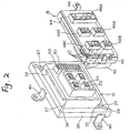
- a first junction box 12 having a large-current circuit 32
- a second junction box 15 having a small-current circuit 44
- the first and second junction boxes 12 and 15 being adapted to be mounted on an instrument panel 10 and a body panel 14, respectively.
- the function of a conventional function box is divided into those of the first and second junction boxes 12 and 15.
- an internal circuit in the form of a bus bar 32 mounted within the first junction box 12 constitutes the large-current circuit while an internal circuit in the form of a bus bar 44 mounted within the second junction box 15 constitutes the small-current circuit.
- the internal circuits of the first and second junction boxes 12 and 15 are not limited to the bus bar, and may be a combination of single-conductor wires and press-connecting terminals, or the internal circuit (large-current circuit) of the first junction box 12 may be constituted by a bus bar while the internal circuit (small-current circuit) of the second junction box 15 may be constituted by single-conductor wires and press-connecting terminals.
- An instrument panel harness 16 is beforehand connected to the first junction box 12 to be connected to the instrument panel 10, and in an automobile assembly line the first junction box 12 and the instrument panel harness 16 are attached to the instrument panel 10.
- the first junction box 12 and the instrument panel harness 16 may be separate from each other, and the two may be connected together in the assembly line simultaneously when attaching them to the instrument panel 10.
- the second junction box 15 to be attached to the body panel 14 is attached to the body panel 14 in the automobile assembly line, and other wire harnesses, that is, a front harness 20, a floor harness 21, a roof harness 22 and a door harness 23, are connected to the second junction box 15.
- the first junction box 12 having the associated wire harness connected thereto, is attached to the instrument panel 10, and also the second junction box 15, having the associated wire harnesses connected thereto, is attached to the body panel 14.
- the first junction box 12 is simultaneously fitted in the second junction box 15, thereby electrically connecting the first and second junction boxes together.
- the instrument panel harness 16 to be connected to the first junction box 12 having the large-current circuit includes a cowl harness without a power circuit 18 connected to a power source 17 such as a battery.
- a cowl harness without a power circuit 18 connected to a power source 17 such as a battery.
- two large-size wire harnesses that is, an instrument panel harness and a cowl harness which have been separate from each other in the conventional construction, are combined together into the instrument panel harness 16 (which is to be attached to the instrument panel 10) including all the wires except the wire 18 connected to the power source 17.
- the wire harness to be connected to the second junction box 15 having the small-current circuit includes the power circuit 18 connecting the power source 17 to the second junction box 15.
- the front harness 20, the floor harness 21, the roof harness 22 and the door harness 23 are connected to the second junction box 15 through respective connectors.
- the first junction box 12 comprises an upper case 30 and a lower case 31, and the bus bar 32, constituting the above large-current circuit, is mounted within a space formed by these cases 30 and 31.
- the bus bar 32 comprises a shared power circuit, an earth circuit, and a large-current power circuit connected to these circuits in a branched manner.
- the first junction box 12 includes relays and fuses connected to the bus bar (large-current circuit) 32.
- the first junction box 12 is mounted on an outer frame 26 (adapted to be fixed to the instrument panel 10) through resilient support members 27, so that the first junction box 12 is movable so as to absorb a dimensional error when fitting the first junction box 12 in the second junction box 15.
- a collective-fitting connector portion 33 for fitting connection to the second junction box 15 is mounted on an upper surface of the upper case 30, and a fuse mounting portion 60 for mounting the above fuses thereon is also mounted on the upper surface of the upper case 30.
- Male terminals 34, connected to the bus bar 32, are projected into the interior of the connector portion 33.
- Mounting portions 35 are provided respectively at four corners of an outer peripheral surface of the upper casing 30, and the resilient support members 27 are mounted respectively at the mounting portions 35.
- the instrument panel harness 16 is connected to the bottom surface of the lower case 31.
- the outer frame 26 of a square shape surrounds the case of the first junction box, and is spaced a predetermined distance from the outer peripheral surface of this case.
- Mounting portions 39 are formed respectively at the inner sides of the four corners of the outer frame 26 respectively facing the mounting portions 35, and the resilient support members 27 are mounted respectively at the mounting portions 39.
- Brackets 40 are formed respectively on predetermined portions of the outer peripheral surface of the outer frame 26, and the outer frame 26 is attached to the instrument panel 10 by the brackets 40.
- the resilient support member 27 comprises a rubber member or a spring, and one end thereof is retained on the mounting portion 35 of the first junction box 12 whereas the other end thereof is retained on the mounting portion 39 of the outer frame 26, and the first junction box 12 is held within the outer frame 26 in such a manner that the first junction box 12 is movable within the outer frame 26.
- the second junction box 15 to be fixed to the body panel 14 comprises an upper case 42 and a lower case 43, and the bus bar 44, constituting the small-current circuit, is mounted within a space formed by these cases 42 and 43.
- the bus bar 44 comprises signal circuits, connected respectively to the front harness 20, the floor harness 21, the roof harness 22 and the door harness 23, and a small-current power circuit.
- a collective-fitting connector portion 45 for fitting connection to the connector portion 33 of the first junction box 12 is formed on an upper surface of the upper case 42 of the second junction box 15.
- Female terminals 47, connected to the bus bar 44, are projected into the interior of the connector portion 45, and are respectively fitted on and electrically connected to the male terminals 34 in the connector portion 33.
- Brackets 46 are formed respectively on predetermined portions of the outer peripheral surface of the upper case 42, and the second junction box 15 is attached to the body panel 14 by the brackets 46.
- a plurality of harness connector portions for fitting respectively on the plurality of wire harnesses are formed on the bottom surface of the lower case 43.
- five harness connector portions 48A to 48E are provided, and a connector 50 of the power circuit 18 is fitted in the harness connector portion 48A, and connectors 51, 52, 53 and 54, secured respectively to ends of the front harness 20, the floor harness 21, the roof harness 22 and the door harness 23, are fitted respectively in the harness connector portions 48B to 48E.
- the instrument panel harness 16 is arranged in position on the instrument panel 10, and the brackets 40, formed on the outer frame 26 of the first junction box 12, are secured to the instrument panel 10, thereby fixing the first junction box 12.
- the second junction box 15 is attached to the body panel 14, and the connectors 50 to 54 of the power circuit 18 and the wire harnesses 20 to 23 are fitted in and connected to the harness connector portions 48A to 48E of the second junction box 15, respectively.
- the power circuit 18 and the wire harnesses 20 to 23 are arranged in position on the body panel 14.
- the fitting of the connectors 50 to 54, the attachment of the first function box 12 to the instrument panel 10, and the attachment of the second junction box 15 to the body panel 14 can be effected in a wide space available before the instrument panel 10 is attached to the body panel 14, and therefore these operations can be carried out efficiently.
- the instrument panel 10 is attached to the body panel 14.
- the collective-fitting connector portions 33 and 45 of the first and second junction boxes 12 and 15 are first brought into contact with each other.
- the resilient support members expand and contract to allow the first junction box 12 to move, thereby eliminating this misregistration.
- the first junction box is movable, and therefore the fitting position is finely adjusted, thereby absorbing an error, so that the collective-fitting connector portions 33 and 45 can be easily fitted together.
- the instrument panel harness 16 can be connected to the wire harnesses 18 and 20 to 23 at one time, and the time and labor required are much reduced as compared with the conventional connector fitting operation. Namely, after the instrument panel 10 is mounted on the body panel 14, the fitting of the connectors of the wire harnesses is not necessary, and also the fixing of the junction box to the body after the fitting of the connectors is not necessary, and therefore the efficiency of the mounting operation can be greatly enhanced.
- each of the instrument panel harness 16, connected to the junction box 12, and the body panel-side wire harnesses, connected to the junction box 15, does not include the power circuit, the signal circuit and the earth circuit in a mixed manner. Therefore the wire harnesses can be of a simple construction.
- the instrument panel harness 16 comprises a bundle of wires that does not include the wire of the power circuit 18, it is necessary to install only one large-size wire harness in a narrow space between the instrument panel 10 and the body panel 14, so that the efficiency of the operation can be enhanced.
- the two connector portions 33 and 45 can not be easily fitted together if the two junction boxes 12 and 15 are fixed.
- the first junction box 12 is movable relative to the instrument panel 10 to such a degree as to absorb a dimensional error, and therefore this fitting operation can be effected smoothly.
- junction box does not always need to be mounted on the panel so as to move relative thereto, and may be fixed thereto.
- both of the first and second junction boxes may be movable.
- the two connector portions 33 and 45 are of the multi-pole type, and the two connector portions 33 and 45 can not be easily fitted together merely by pressing the instrument panel 10 and body panel 14, there may be used an arrangement in which through holes, which can face each other, formed respectively through the first and second junction boxes 12 and 15, bolts are passed, and nuts are threaded on these bolts, thereby fitting the two connector portions 33 and 45 together.
- these bolts serve also as fasteners for fastening the instrument panel 10 and the body panel 14 together.
Landscapes
- Engineering & Computer Science (AREA)
- Chemical & Material Sciences (AREA)
- Combustion & Propulsion (AREA)
- Transportation (AREA)
- Mechanical Engineering (AREA)
- Connection Or Junction Boxes (AREA)
- Coupling Device And Connection With Printed Circuit (AREA)
- Details Of Connecting Devices For Male And Female Coupling (AREA)
- Instrument Panels (AREA)
Applications Claiming Priority (4)
| Application Number | Priority Date | Filing Date | Title |
|---|---|---|---|
| JP30891195 | 1995-11-28 | ||
| JP308911/95 | 1995-11-28 | ||
| JP07308911A JP3046537B2 (ja) | 1995-11-28 | 1995-11-28 | 自動車のインストルメントパネルハーネスの接続構造 |
| US08/753,339 US5771575A (en) | 1995-11-28 | 1996-11-22 | Automobile instrument panel harness-connecting construction |
Publications (3)
| Publication Number | Publication Date |
|---|---|
| EP0776790A2 true EP0776790A2 (fr) | 1997-06-04 |
| EP0776790A3 EP0776790A3 (fr) | 1999-12-08 |
| EP0776790B1 EP0776790B1 (fr) | 2002-03-20 |
Family
ID=26565734
Family Applications (1)
| Application Number | Title | Priority Date | Filing Date |
|---|---|---|---|
| EP96119010A Expired - Lifetime EP0776790B1 (fr) | 1995-11-28 | 1996-11-27 | Structure de connexion d'un faisceau de cables du tableau de bord d'un véhicule |
Country Status (3)
| Country | Link |
|---|---|
| US (1) | US5771575A (fr) |
| EP (1) | EP0776790B1 (fr) |
| JP (1) | JP3046537B2 (fr) |
Cited By (2)
| Publication number | Priority date | Publication date | Assignee | Title |
|---|---|---|---|---|
| GB2337871B (en) * | 1998-05-29 | 2001-11-07 | 3Com Technologies Ltd | Test connector |
| DE10233192B4 (de) * | 2001-07-23 | 2007-06-28 | Sumitomo Wiring Systems, Ltd., Yokkaichi | Verbindungsgehäuse |
Families Citing this family (15)
| Publication number | Priority date | Publication date | Assignee | Title |
|---|---|---|---|---|
| DE29621257U1 (de) * | 1996-12-06 | 1998-04-02 | Robert Bosch Gmbh, 70469 Stuttgart | Verbinderanordnung eines Steuerungssystems mit einem Steuergerät in einem Kraftfahrzeug |
| US6048020A (en) * | 1998-02-11 | 2000-04-11 | Yazaki Corporation | Electrical interconnection module for vehicle instrument panel |
| US6089894A (en) * | 1998-05-29 | 2000-07-18 | 3Com Technologies | Test connector |
| EP2264836B1 (fr) * | 1999-09-27 | 2012-12-19 | Autonetworks Technologies, Ltd. | Connecteur |
| JP3721026B2 (ja) * | 1999-11-24 | 2005-11-30 | 矢崎総業株式会社 | インストルメントパネル用ワイヤハーネスの接続構造 |
| DE10208106B4 (de) * | 2002-02-26 | 2013-04-11 | Roof Systems Germany Gmbh | Baugruppe für eine Fahrzeugtür |
| US6621688B1 (en) | 2002-06-26 | 2003-09-16 | Alcoa Fujikura Limited | Electrical distribution system having integral junction box for instrument panel application |
| JP4310663B1 (ja) * | 2008-01-31 | 2009-08-12 | 三菱自動車工業株式会社 | サービスプラグの取付構造 |
| US7993155B2 (en) | 2008-09-19 | 2011-08-09 | Better Place GmbH | System for electrically connecting batteries to electric vehicles |
| US8006793B2 (en) * | 2008-09-19 | 2011-08-30 | Better Place GmbH | Electric vehicle battery system |
| US20110223459A1 (en) * | 2008-09-19 | 2011-09-15 | Yoav Heichal | Multi-Motor Latch Assembly |
| JP2011093374A (ja) * | 2009-10-28 | 2011-05-12 | Yazaki Corp | ワイヤハーネス、及び、電子機器制御システム |
| JP2012040953A (ja) * | 2010-08-19 | 2012-03-01 | Yazaki Corp | 電装システム |
| DE102010045590A1 (de) * | 2010-09-16 | 2012-03-22 | Airbus Operations Gmbh | Vorrichtung zur Befestigung eines elektrischen Geräts an einem Flugzeugmonument |
| JP6870533B2 (ja) * | 2017-08-23 | 2021-05-12 | 株式会社オートネットワーク技術研究所 | 電気部品付ワイヤーハーネスおよび電気部品付ワイヤーハーネスの組付構造 |
Citations (1)
| Publication number | Priority date | Publication date | Assignee | Title |
|---|---|---|---|---|
| JPH01142345A (ja) | 1987-11-30 | 1989-06-05 | Matsushita Electric Ind Co Ltd | 床暖房装置 |
Family Cites Families (8)
| Publication number | Priority date | Publication date | Assignee | Title |
|---|---|---|---|---|
| GB1601461A (en) * | 1977-05-21 | 1981-10-28 | Amp Inc | Electrical junction box |
| JPH0357055Y2 (fr) * | 1987-07-15 | 1991-12-25 | ||
| JPH064396B2 (ja) * | 1988-02-18 | 1994-01-19 | 矢崎総業株式会社 | インストルメントパネル部のワイヤーハーネス装置 |
| JPH0635816Y2 (ja) * | 1988-03-25 | 1994-09-21 | 矢崎総業株式会社 | インストルメントパネル用ワイヤーハーネス装置 |
| JP2747454B2 (ja) * | 1988-07-13 | 1998-05-06 | 矢崎総業株式会社 | 車輛用電気接続装置の取付構造 |
| DE4139434C2 (de) * | 1990-11-30 | 1997-01-30 | Yazaki Corp | Aufbau einer elektrischen Verkabelung für elektrische Komponenten in einem Fahrzeugarmaturenbrett und zum Anschluß an das Bordnetz eines Kraftfahrzeugs |
| JP3107113B2 (ja) * | 1992-06-09 | 2000-11-06 | 矢崎総業株式会社 | 電気接続箱 |
| JP2989457B2 (ja) * | 1993-02-17 | 1999-12-13 | 矢崎総業株式会社 | メータモジュール |
-
1995
- 1995-11-28 JP JP07308911A patent/JP3046537B2/ja not_active Expired - Fee Related
-
1996
- 1996-11-22 US US08/753,339 patent/US5771575A/en not_active Expired - Fee Related
- 1996-11-27 EP EP96119010A patent/EP0776790B1/fr not_active Expired - Lifetime
Patent Citations (1)
| Publication number | Priority date | Publication date | Assignee | Title |
|---|---|---|---|---|
| JPH01142345A (ja) | 1987-11-30 | 1989-06-05 | Matsushita Electric Ind Co Ltd | 床暖房装置 |
Cited By (2)
| Publication number | Priority date | Publication date | Assignee | Title |
|---|---|---|---|---|
| GB2337871B (en) * | 1998-05-29 | 2001-11-07 | 3Com Technologies Ltd | Test connector |
| DE10233192B4 (de) * | 2001-07-23 | 2007-06-28 | Sumitomo Wiring Systems, Ltd., Yokkaichi | Verbindungsgehäuse |
Also Published As
| Publication number | Publication date |
|---|---|
| EP0776790B1 (fr) | 2002-03-20 |
| US5771575A (en) | 1998-06-30 |
| JPH09154216A (ja) | 1997-06-10 |
| JP3046537B2 (ja) | 2000-05-29 |
| EP0776790A3 (fr) | 1999-12-08 |
Similar Documents
| Publication | Publication Date | Title |
|---|---|---|
| US5771575A (en) | Automobile instrument panel harness-connecting construction | |
| EP0776789B1 (fr) | Structure de connexion d'un faisceau de cables du tableau de bord d'un véhicule | |
| US6077102A (en) | Top down electrical distribution center assembly | |
| JPH0613558Y2 (ja) | 自動車用配線装置 | |
| US5438310A (en) | Fuse box | |
| EP0534659B1 (fr) | Méthode d'aménagement d'un faisceau de câbles pour une porte | |
| JPH0649064Y2 (ja) | 電気接続箱と外部コネクタとの接続構造 | |
| US10608385B2 (en) | Connector structure and electric vehicle | |
| US5502615A (en) | Meter module assembly | |
| US4954102A (en) | Wiring connection apparatus | |
| JP2705043B2 (ja) | 電気接続箱 | |
| US5668415A (en) | Arrangement of harnesses in a vehicle | |
| JPH1140281A (ja) | ジョイントコネクタの固定構造 | |
| JP3046536B2 (ja) | 自動車用の電気接続箱および該電気接続箱を備えたインストルメントパネルハーネスの接続構造 | |
| EP0701925B1 (fr) | Boítier de connexion pour véhicule automobile | |
| JP3916283B2 (ja) | ジャンクションボックス | |
| JPH0517825Y2 (fr) | ||
| JP3108608B2 (ja) | 電気接続箱 | |
| JPH0317550Y2 (fr) | ||
| JP3056988B2 (ja) | 可動式電気接続箱および自動車のインストルメントパネル用ワイヤハーネスの取付構造 | |
| JPH0783536B2 (ja) | 電気接続箱の車体等への取付構造 | |
| DE69619934T2 (de) | Kabelbaumanlage für das Armaturenbrett eines Fahrzeuges | |
| JP2956741B2 (ja) | 自動車用配線装置 | |
| JPH0534178Y2 (fr) | ||
| JP3321062B2 (ja) | 配線接続装置 |
Legal Events
| Date | Code | Title | Description |
|---|---|---|---|
| PUAI | Public reference made under article 153(3) epc to a published international application that has entered the european phase |
Free format text: ORIGINAL CODE: 0009012 |
|
| AK | Designated contracting states |
Kind code of ref document: A2 Designated state(s): DE FR GB |
|
| PUAL | Search report despatched |
Free format text: ORIGINAL CODE: 0009013 |
|
| AK | Designated contracting states |
Kind code of ref document: A3 Designated state(s): DE FR GB |
|
| 17P | Request for examination filed |
Effective date: 20000516 |
|
| 17Q | First examination report despatched |
Effective date: 20000815 |
|
| GRAG | Despatch of communication of intention to grant |
Free format text: ORIGINAL CODE: EPIDOS AGRA |
|
| GRAG | Despatch of communication of intention to grant |
Free format text: ORIGINAL CODE: EPIDOS AGRA |
|
| GRAH | Despatch of communication of intention to grant a patent |
Free format text: ORIGINAL CODE: EPIDOS IGRA |
|
| REG | Reference to a national code |
Ref country code: GB Ref legal event code: IF02 |
|
| GRAH | Despatch of communication of intention to grant a patent |
Free format text: ORIGINAL CODE: EPIDOS IGRA |
|
| GRAA | (expected) grant |
Free format text: ORIGINAL CODE: 0009210 |
|
| AK | Designated contracting states |
Kind code of ref document: B1 Designated state(s): DE FR GB |
|
| REF | Corresponds to: |
Ref document number: 69619934 Country of ref document: DE Date of ref document: 20020425 |
|
| ET | Fr: translation filed | ||
| ET | Fr: translation filed | ||
| PLBE | No opposition filed within time limit |
Free format text: ORIGINAL CODE: 0009261 |
|
| STAA | Information on the status of an ep patent application or granted ep patent |
Free format text: STATUS: NO OPPOSITION FILED WITHIN TIME LIMIT |
|
| 26N | No opposition filed |
Effective date: 20021223 |
|
| PGFP | Annual fee paid to national office [announced via postgrant information from national office to epo] |
Ref country code: FR Payment date: 20031110 Year of fee payment: 8 |
|
| PGFP | Annual fee paid to national office [announced via postgrant information from national office to epo] |
Ref country code: GB Payment date: 20031126 Year of fee payment: 8 |
|
| PGFP | Annual fee paid to national office [announced via postgrant information from national office to epo] |
Ref country code: DE Payment date: 20031204 Year of fee payment: 8 |
|
| PG25 | Lapsed in a contracting state [announced via postgrant information from national office to epo] |
Ref country code: GB Free format text: LAPSE BECAUSE OF NON-PAYMENT OF DUE FEES Effective date: 20041127 |
|
| PG25 | Lapsed in a contracting state [announced via postgrant information from national office to epo] |
Ref country code: DE Free format text: LAPSE BECAUSE OF NON-PAYMENT OF DUE FEES Effective date: 20050601 |
|
| GBPC | Gb: european patent ceased through non-payment of renewal fee |
Effective date: 20041127 |
|
| PG25 | Lapsed in a contracting state [announced via postgrant information from national office to epo] |
Ref country code: FR Free format text: LAPSE BECAUSE OF NON-PAYMENT OF DUE FEES Effective date: 20050729 |
|
| REG | Reference to a national code |
Ref country code: FR Ref legal event code: ST |